:+86 15106109009
:sales@couplingzy.com


 English
  русский
  Español
  عربى
عربى  Português
  Deutsch
  Türk
Türk  Indonesia

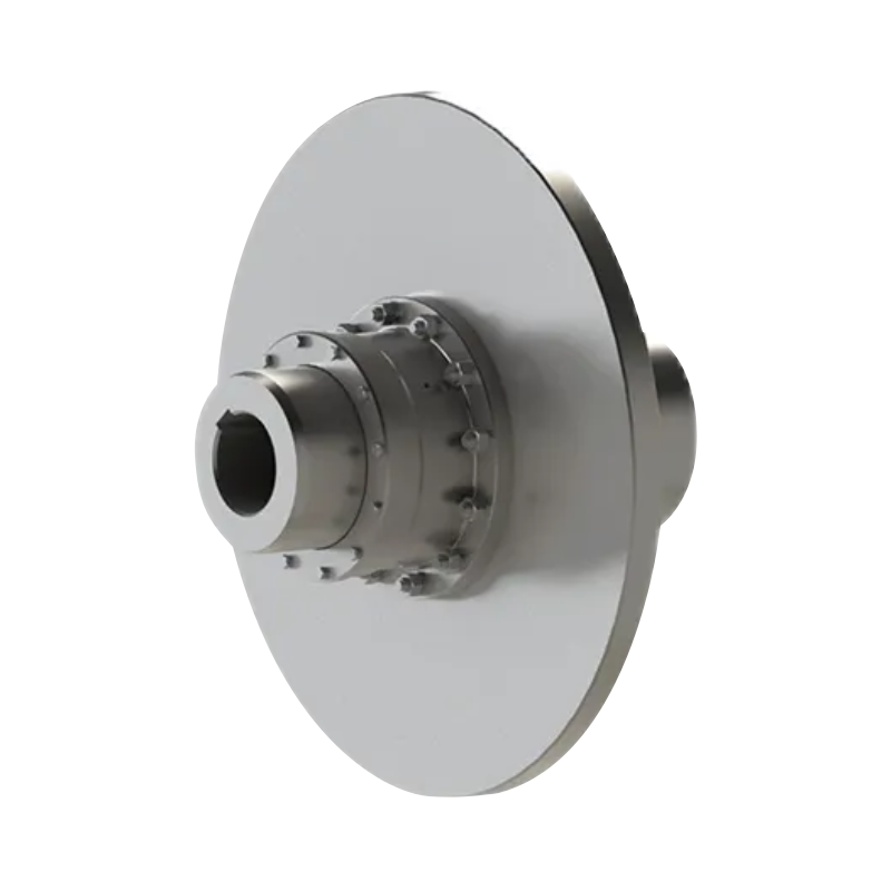
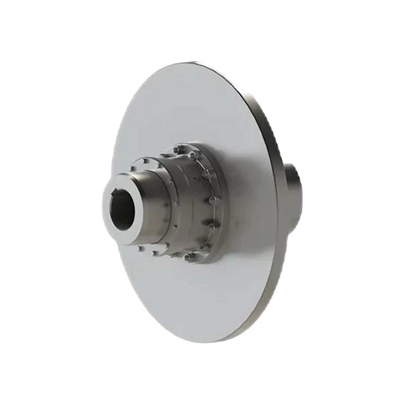
QWL Type Ball Cage Universal Coupling: Constant-Velocity Power Transmission for Heavy-Duty Precision Applications
Content
- 1 1. The Operating Principle of a Ball Cage Universal Coupling
- 2 2. Product Advantages Compared with Conventional Couplings
- 3 3. Main Technical Characteristics
- 4 4. Application Areas
- 5 5. Engineering Selection Guidelines
- 6 6. Manufacturing and Quality Strengths
- 7 7. Installation Recommendations
- 8 8. Maintenance and Service Life
- 9 9. Safety and Reliability Considerations
- 10 10. Why Work with an Integrated Coupling Manufacturer?
- 11 11. Practical Selection Example
- 12 12. Frequently Asked Questions
- 12.1 Q1. What type of coupling is the QWL series?
- 12.2 Q2. What is the main advantage of the ball cage design?
- 12.3 Q3. What torque range is available?
- 12.4 Q4. What is the maximum allowable shaft angle?
- 12.5 Q5. Can the coupling accommodate axial movement?
- 12.6 Q6. Is the QWL coupling suitable for high-shock applications?
- 12.7 Q7. Does the coupling require lubrication?
- 12.8 Q8. Can the QWL coupling replace a gear coupling?
- 12.9 Q9. Is customization available?
- 12.10 Q10. What information should be provided for a quotation?
- 12.11 Q11. Is the coupling appropriate for precision machinery?
- 12.12 Q12. How does the manufacturer support quality?
- 13 13. Conclusion
- 14 References
- 15 Product: QWL Type Ball Cage Universal Coupling
Modern industrial machinery increasingly requires power transmission systems that can accommodate shaft misalignment without sacrificing synchronization, efficiency, or service life. In rolling mills, machine tools, conveyor systems, construction machinery, and other demanding equipment, the shafts connected by a coupling may not remain perfectly aligned during operation. Thermal expansion, structural deflection, installation tolerances, load changes, and movement between machine sections can all produce angular displacement or limited axial movement.
The QWL Type Ball Cage Universal Coupling is designed for these operating conditions. It is a flexible coupling with a non-elastic transmission element that uses precision steel balls, cage windows, and specially shaped raceways to transmit torque. Unlike conventional universal couplings that can create speed fluctuations when the connected shafts operate at an angle, the QWL design is intended to maintain constant-velocity, synchronous rotation between the driving and driven shafts.
Its operating range covers nominal torque ratings from 180 N·m to 10,000 N·m, with swing diameters from 85 mm to 275 mm and allowable maximum shaft inclination angles of approximately 16° to 20°, depending on the model. This combination of angular flexibility, high torque capacity, and constant-velocity transmission makes the series suitable for equipment that requires both mechanical adaptability and precise motion control.
Manufactured by Zhongye Heavy Industry Technology (Zhenjiang) Co., Ltd., the QWL series forms part of a broader range of industrial coupling solutions. The manufacturer integrates product development, engineering, manufacturing, inspection, and technical service, allowing customers to obtain both standard products and customized coupling designs for special operating conditions.
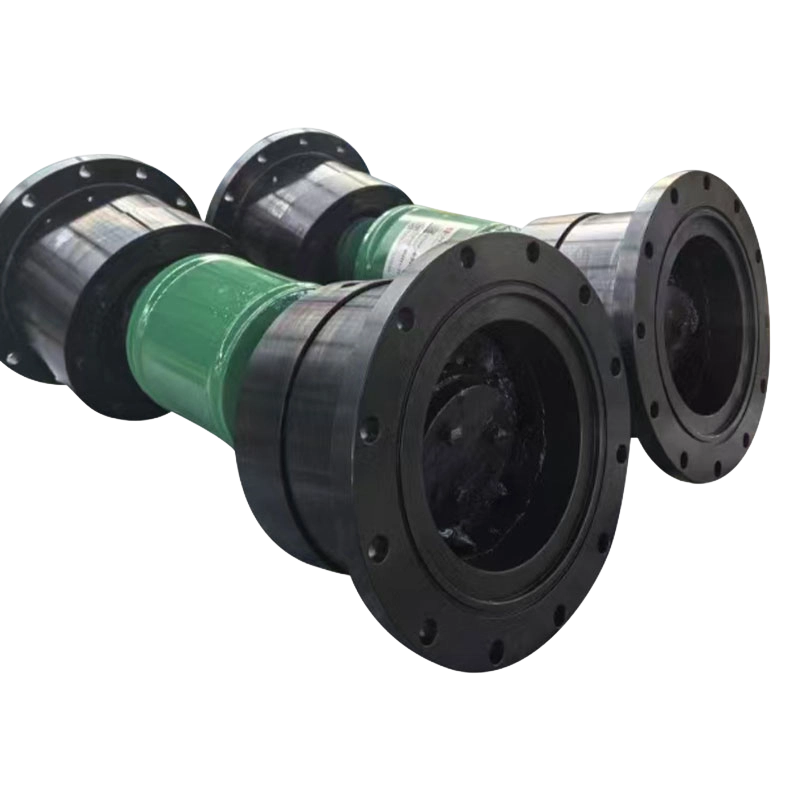
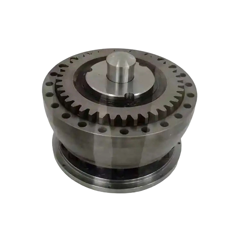
QWL Type Ball Cage Universal Coupling
1. The Operating Principle of a Ball Cage Universal Coupling
A universal coupling connects two shafts whose centerlines may intersect at an angle or experience a limited relative displacement. The central engineering challenge is to transfer torque smoothly while reducing the speed variation, vibration, and contact stress that can occur when conventional joint mechanisms operate away from perfect alignment.
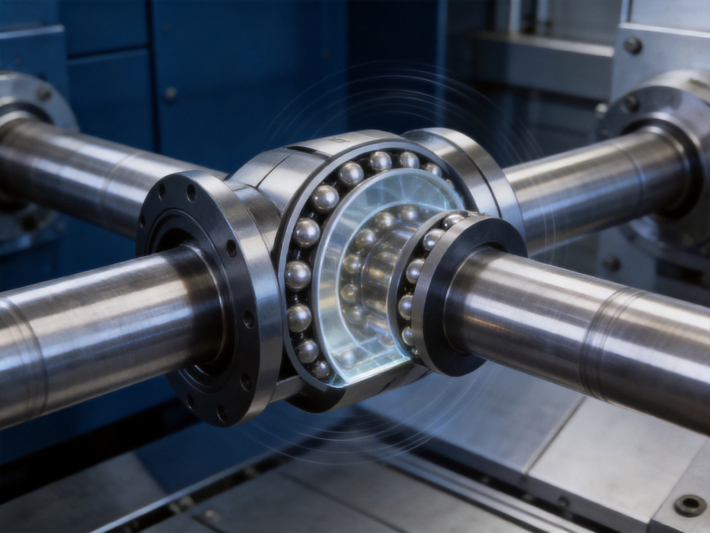
The QWL Type Ball Cage Universal Coupling addresses this challenge through a ball-and-raceway transmission system. Precision steel balls are positioned within the openings of a retaining cage. The balls engage with corresponding raceways formed in the coupling’s driving and driven components. As the input shaft rotates, torque is transferred through the rolling contact between the balls and the raceways.
The ball cage keeps the rolling elements correctly positioned and distributes the load around the coupling. Because the balls roll between accurately formed contact surfaces rather than relying on sliding friction alone, the coupling can accommodate angular movement while preserving a high degree of rotational uniformity. The raceways are arranged symmetrically to support balanced load transmission in both directions of operation.
When the shafts operate with a shaft inclination angle, the geometric relationship between the raceways and balls allows the driven shaft to follow the speed of the driving shaft more consistently than a basic cross-shaft universal joint. This constant-velocity characteristic is particularly valuable in applications where speed pulsation could affect product quality, positioning accuracy, vibration levels, or the service life of connected components.
The coupling is not based on rubber, polyurethane, or another flexible polymer element. It therefore belongs to the category of flexible couplings with non-elastic elements. Flexibility is obtained from the kinematic movement of the ball cage and raceway system rather than from elastic deformation of a sleeve or disc pack.
1.1 Torque transmission through rolling contact
Rolling contact provides several important operating benefits. It can reduce sliding losses at the principal torque-transmitting interface, limit friction-related heat generation, and support repeated angular movement when the coupling is correctly lubricated and aligned within its specified limits.
Rolling elements also allow the coupling to respond to changing angular conditions without depending on the fatigue life of an elastomeric insert. This is advantageous in heavy industrial equipment where high torque, impact loading, elevated duty cycles, and harsh environmental conditions can place considerable demands on elastic components.
1.2 Constant-velocity performance
A standard cross-shaft universal coupling can generate a periodic fluctuation in driven-shaft speed when the operating angle increases. In a single-joint arrangement, the output speed accelerates and decelerates during each revolution. These fluctuations may produce torsional vibration, noise, additional bearing loads, and uneven motion.
The QWL ball cage geometry is designed to avoid this characteristic speed fluctuation. Its symmetric raceway arrangement supports a constant-velocity relationship between the input and output shafts, subject to the rated operating conditions and correct installation. This makes the coupling especially appropriate for systems in which the driven component must rotate smoothly even while operating at an angle.
2. Product Advantages Compared with Conventional Couplings
The QWL series combines characteristics that are often difficult to achieve simultaneously: high torque capacity, angular flexibility, constant-velocity operation, impact resistance, and a compact mechanical transmission path. Its advantages become clearer when compared with common alternatives.
2.1 Compared with conventional cross-shaft universal couplings
The most significant difference is the transmission kinematics. Conventional cross-shaft universal couplings commonly use a cross-shaped trunnion and bearing arrangement. Although these couplings are widely used and can accommodate angular misalignment, a single cross-shaft joint normally produces speed fluctuation when operating at an angle.
The QWL design uses a ball cage and raceway mechanism to maintain more uniform angular velocity. This can reduce torsional pulsation and improve the motion quality of equipment driven through an angled shaft arrangement. It is therefore a strong alternative where a conventional universal joint would require additional synchronization arrangements or where speed irregularity would be unacceptable.
The QWL coupling also distributes torque through multiple precision balls. Instead of concentrating the load in a small number of cross-joint bearing points, its rolling elements share the transmitted force around the coupling. This distribution can improve load stability and resistance to impact when the coupling is selected correctly for the application.
2.2 Compared with elastic couplings
Elastic couplings use a flexible element to absorb misalignment, damp vibration, and provide some degree of shock protection. They are effective in many applications, but their performance is influenced by the fatigue, temperature resistance, chemical compatibility, and aging behavior of the elastic material.
The QWL coupling does not depend on an elastomer to transmit torque. This avoids the material aging and temperature limitations associated with many rubber or polymer components. It can be advantageous in heavy-duty systems with frequent starts and stops, high torque, severe mechanical loading, or an environment in which elastic materials may deteriorate.
At the same time, the QWL should not be viewed as a universal replacement for every elastic coupling. Elastic couplings can provide useful torsional damping and electrical isolation, while the QWL is primarily selected for constant-velocity transmission, angular flexibility, and high mechanical precision. The final selection should consider torsional resonance, shock loads, speed, temperature, lubrication, and maintenance requirements.
2.3 Compared with gear couplings
Gear couplings can transmit high torque and accommodate angular or axial movement. However, they depend on toothed engagement and lubrication between external and internal gear teeth. Tooth wear, backlash, tooth edge loading, and lubrication contamination may affect their performance over time.
The QWL ball cage mechanism provides a different load-transmission principle. Precision balls roll along dedicated raceways, and the coupling is designed around constant-velocity movement rather than gear-tooth engagement. This can be beneficial in applications where smooth motion and low speed fluctuation are more important than the very high torque density often associated with large gear couplings.
2.4 Compared with rigid couplings
Rigid couplings are suitable when the connected shafts are permanently aligned and the machine structure is sufficiently stiff to prevent relative movement. They do not compensate for angular misalignment and may transfer excessive reaction forces to bearings if alignment changes during operation.
The QWL coupling is a better choice when shaft inclination or movement is unavoidable. Its allowable angular capacity enables the connected equipment to operate with a controlled degree of misalignment while maintaining rotational continuity. This can reduce the need for extremely precise static alignment, although proper installation remains essential.
3. Main Technical Characteristics
The QWL series is available in nine primary sizes, from QWL1 through QWL9. The range allows engineers to match the coupling to the required torque, shaft diameter, installation envelope, and angular movement.
| Model | Nominal Torque | Maximum Inclination Angle | Reference Swing Diameter | Typical Shaft Bore Range |
|---|---|---|---|---|
| QWL1 | 180 N·m | 16° | 85 mm | 14–35 mm |
| QWL2 | 355 N·m | 16° | 100 mm | 32–45 mm |
| QWL3 | 800 N·m | 18° | 130 mm | 45–70 mm |
| QWL4 | 1,400 N·m | 18° | 150 mm | 55–75 mm |
| QWL5 | 2,240 N·m | 18° | 175 mm | 63–90 mm |
| QWL6 | 3,150 N·m | 18° | 200 mm | 71–110 mm |
| QWL7 | 4,500 N·m | 18° | 220 mm | 80–120 mm |
| QWL8 | 6,300 N·m | 20° | 245 mm | 90–140 mm |
| QWL9 | 10,000 N·m | 20° | 275 mm | 100–160 mm |
The table provides a general overview. Detailed dimensions vary according to shaft bore, shaft construction, coupling length, and selected configuration. Engineering selection should always use the applicable product drawing and technical data sheet.
3.1 Torque range
The nominal torque range of 180 N·m to 10,000 N·m covers small and medium industrial drive systems as well as heavy-duty equipment. The lower models can serve precision conveyor mechanisms, smaller machine-tool systems, and compact drive assemblies. The larger models are suitable for demanding industrial machinery, including rolling equipment, heavy conveyors, and large slewing or articulated mechanisms.
Nominal torque is specified for the rated operating condition and with the shaft inclination angle at zero degrees. As the operating angle increases, the actual permissible torque, speed, and service life may be affected by contact forces, lubrication conditions, and the dynamic behavior of the machine. Engineers should therefore apply an appropriate service factor instead of selecting a coupling based only on the average motor torque.
3.2 Angular capacity
Depending on the model, the allowable maximum shaft inclination angle is 16°, 18°, or 20°. These values provide considerable flexibility compared with many conventional shaft couplings. The capacity is useful in equipment where a shaft must pass between moving machine sections or where the connected shafts operate at a permanent angle.
The maximum angle is a design limit, not a recommended continuous operating target for every application. Continuous operation near the maximum value may increase contact forces, heat generation, lubrication demands, and wear. Where possible, the coupling should operate at a lower working angle with sufficient allowance for dynamic movement and installation tolerance.
3.3 Axial extension and contraction
The product data includes coupling length parameters and total length extension or contraction values. These features allow the coupling to accommodate a controlled amount of axial movement in addition to angular displacement. Axial movement can result from thermal expansion, machine travel, structural deflection, or changes in the relative position of connected equipment.
Axial movement must remain within the specified range. Excessive extension, compression, or end loading can alter the ball contact pattern and increase the force applied to adjacent bearings. During installation, the coupling should be set at the specified reference length and checked throughout the machine’s complete operating stroke.
3.4 Shaft bore options
The QWL series supports a broad selection of shaft bore diameters. Depending on the model, the available bore range extends from approximately 14 mm to 160 mm. Both through-shaft and welded-shaft configurations are represented in the technical information, allowing the product to be adapted to different shaft arrangements.
Bore selection should account for shaft diameter, keyway requirements, fit tolerance, transmitted torque, surface condition, and the required method of assembly. A correct H7 bore specification and compatible shaft tolerance can help achieve reliable torque transmission while allowing practical installation and removal.
3.5 Overload capability
The technical information states that short-term overload torque during starting and braking may reach three times the normal torque, with a duration not exceeding 15 seconds. This capability is useful for drives that experience transient acceleration, deceleration, or short-duration impact loading.
The overload rating must not be treated as a continuous operating capacity. Repeated overload events, long acceleration periods, frequent reversing, or high inertia loads may require a larger coupling. The starting method, motor power, driven inertia, braking torque, duty cycle, and number of cycles per hour should all be considered in the selection calculation.
4. Application Areas
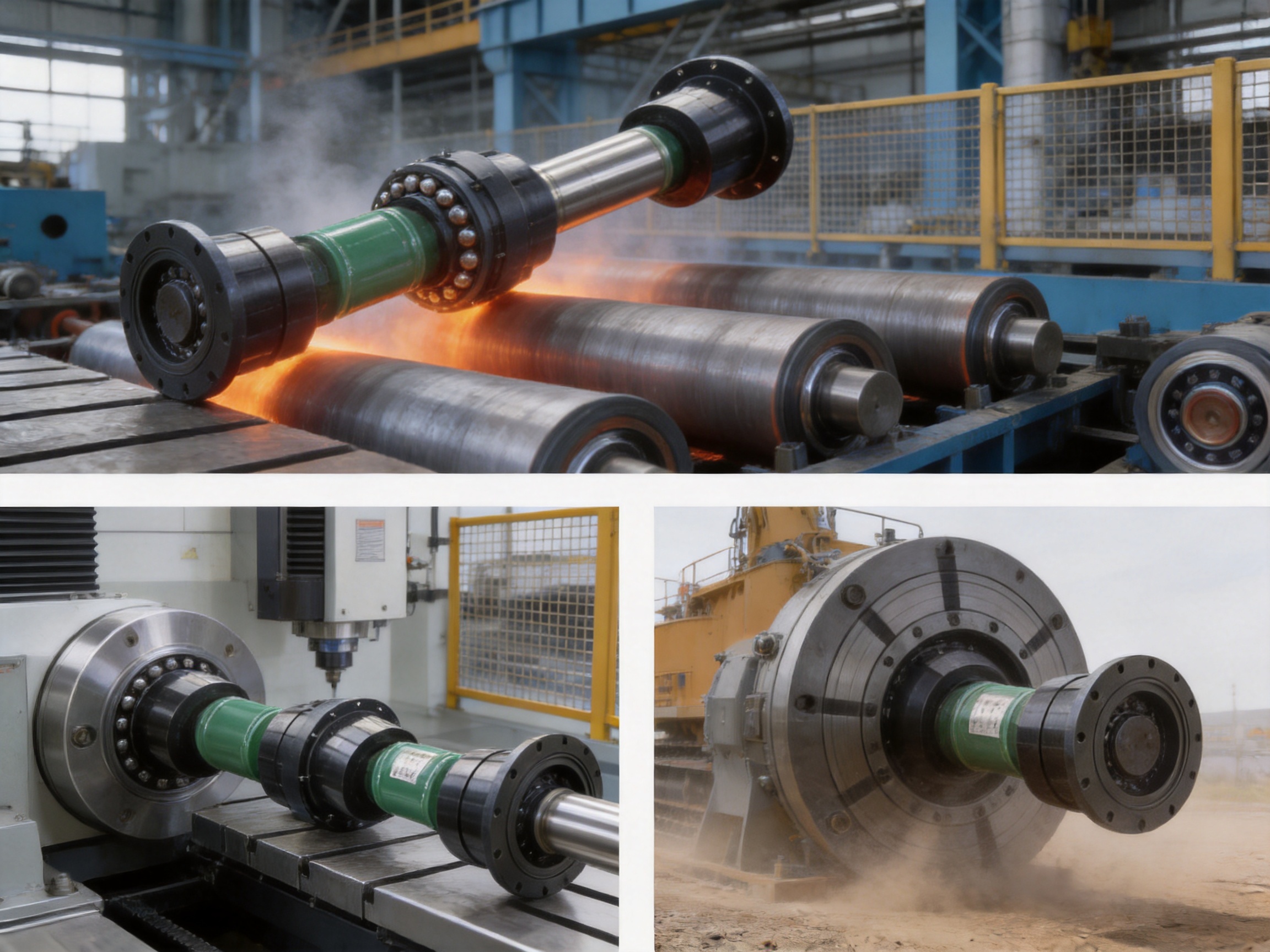
4.1 Metallurgical rolling mill roller tables
Rolling mill roller tables operate in a demanding environment characterized by heavy loads, frequent starts and stops, shock forces, contamination, and thermal variation. The drive shaft may need to accommodate movement between the motor, gearbox, and roller assembly while continuing to deliver synchronized rotation.
The QWL coupling is well suited to this type of application because its ball cage transmission supports angular movement and high torque. Its constant-velocity performance can help maintain uniform roller rotation, while its non-elastic construction avoids dependence on a polymer element that may be affected by heat, oil, scale, or repeated impact.
For rolling mill use, engineers should pay particular attention to sealing, lubrication, cooling, maintenance access, and protection from metal particles. The coupling should also be selected for the peak rolling load rather than only the motor’s nominal output.
4.2 CNC machine-tool spindles
Machine tools require smooth and accurate transmission. Speed pulsation can affect surface finish, tool life, positioning quality, and vibration levels. A constant-velocity coupling can help maintain a more uniform rotational relationship between connected shafts, especially where the drive arrangement requires angular movement.
The QWL series may be selected for suitable machine-tool mechanisms when the coupling’s size, rotational speed, balance, lubrication, and inertia are compatible with the spindle system. High-speed applications require detailed dynamic analysis, including balancing, critical-speed assessment, bearing reaction forces, and enclosure design.
For precision equipment, installation accuracy is essential. The coupling should be mounted without forcing the shafts into alignment, and runout should be verified with appropriate measurement equipment. Any contamination introduced during assembly may affect the rolling contacts and should be prevented.
4.3 Precision conveyor lines
Precision conveyors used in manufacturing, packaging, electronics, or automated assembly may require controlled speed, reliable indexing, and limited vibration. If the conveyor layout includes articulated sections or shafts operating at an angle, a constant-velocity coupling can help preserve smooth motion across the drive line.
The QWL coupling can also provide flexibility where conveyor frames move relative to one another or where thermal changes alter the shaft position. The selected model should be based on starting torque, belt or chain tension, conveyor acceleration, shock loading, shaft diameter, and the required service factor.
4.4 Slewing mechanisms for construction machinery
Construction machinery often contains large articulated structures and mechanisms that operate under changing loads. Slewing and positioning systems may require a coupling that can manage angular movement while transmitting substantial torque.
The larger QWL models, with nominal torque ratings up to 10,000 N·m, can be considered for heavy-duty applications where their dimensions and operating limits are appropriate. The coupling’s impact resistance and non-elastic torque path can be advantageous in equipment exposed to intermittent loading and frequent changes in direction.
4.5 Mining, lifting, paper, port, and water equipment
The manufacturer’s coupling products are used across mining equipment, lifting equipment, paper machinery, port machinery, water equipment, and other industrial sectors. These applications often require a combination of torque capacity, durability, misalignment compensation, and serviceability.
For each application, the QWL coupling should be evaluated against environmental conditions such as dust, moisture, corrosive substances, ambient temperature, washdown procedures, and accessibility for inspection. Protective covers and suitable lubrication arrangements may be required to maintain the rolling contact surfaces.
5. Engineering Selection Guidelines
Selecting a universal coupling should begin with the complete operating profile rather than a single torque value. The following factors should be documented before choosing a model.
5.1 Calculate the operating torque
Operating torque can be calculated from power and rotational speed using the appropriate engineering relationship. The calculated torque should then be multiplied by service factors that reflect starting conditions, braking, shock loading, load variation, operating hours, and the characteristics of the driven machine.
The selected nominal torque should exceed the calculated design torque with an adequate margin. If the equipment undergoes frequent reversing or high-inertia acceleration, the transient torque may govern the selection. The short-term three-times nominal torque allowance should be considered only within the stated time limit and operating conditions.
5.2 Determine the working angle
Measure or calculate the actual angular relationship between the driving and driven shafts under static and dynamic conditions. The maximum angle may occur during machine movement rather than at rest. Deflection under load, thermal expansion, and structural movement should be included.
Do not use the maximum catalog angle as the routine design angle unless the application has been specifically evaluated for that condition. A lower working angle generally provides more operating margin and may contribute to longer service life.
5.3 Check axial movement
Determine whether the shafts move toward or away from one another during operation. Record the minimum and maximum center distance and compare it with the coupling’s specified length range and extension or contraction allowance.
Axial movement should occur freely within the intended mechanism. If the coupling is accidentally installed at the end of its available travel, thermal expansion or machine movement may create unwanted axial loads.
5.4 Verify speed and dynamic behavior
Rotational speed affects lubrication, balance, contact forces, temperature, and vibration. The coupling should be checked for its intended speed range, particularly in machine-tool and precision-conveyor applications.
Where the coupling is used at high speed, engineers should review the rotating mass, moment of inertia, balance grade, shaft critical speeds, and the influence of the coupling on the connected bearings. The QWL technical data includes moment-of-inertia values for the different models, supporting more complete drive-train calculations.
5.5 Select the correct bore and connection style
Confirm the shaft diameter, keyway form, shaft extension, hub length, access direction, and assembly method. Through-shaft and welded-shaft configurations may require different installation procedures. The connection should be capable of transmitting the design torque without fretting, slip, or excessive local stress.
5.6 Consider the environment
Environmental conditions may include high temperature, water spray, dust, scale, oil mist, corrosive chemicals, and outdoor exposure. These factors influence sealing, lubrication, material selection, surface treatment, inspection intervals, and protective guarding.
When the coupling is installed in a contaminated area, a suitable cover can reduce the entry of foreign matter. In wet or corrosive environments, the selected materials and surface protection should be confirmed with the manufacturer before production.
6. Manufacturing and Quality Strengths
The performance of a ball cage universal coupling depends heavily on manufacturing precision. The raceway geometry, ball size consistency, cage accuracy, concentricity, surface finish, heat treatment, and final assembly condition all influence the way the coupling transmits torque.
Zhongye Heavy Industry Technology (Zhenjiang) Co., Ltd. integrates research and development, manufacturing, sales, and technical service. This integrated structure allows product requirements to move through engineering, production, inspection, and after-sales support without relying exclusively on disconnected suppliers.
6.1 Dedicated production facilities
The company’s new workshop covers approximately 16,463.52 square meters. It includes a heavy workshop of about 5,500 square meters, a precision workshop of approximately 4,600 square meters, office facilities, a warehouse, and supporting areas.
The separation of heavy and precision production areas is valuable for coupling manufacturing. Heavy machining and handling operations can be organized separately from processes requiring tighter control of cleanliness, dimensional accuracy, and assembly conditions. This layout supports efficient production while helping reduce the risk of cross-contamination between different manufacturing stages.
6.2 Engineering and product development
The company has experience with many coupling categories, including toothed couplings, elastic sleeve pin couplings, elastic pin couplings, gear couplings with elastic pins, universal couplings, tire couplings, jaw couplings, star couplings, diaphragm couplings, drum couplings, grid couplings, Oldham couplings, flange couplings, clip-shell couplings, roller-chain couplings, and safety couplings.
This product diversity gives the engineering team a broad understanding of different transmission principles. It also supports the selection of the most suitable coupling type for each application instead of forcing every customer toward one standard design.
6.3 Precision manufacturing process
A reliable ball cage coupling requires controlled manufacturing at every stage. The typical process begins with material verification and blank preparation. Forged, cast, or machined blanks are inspected for dimensional condition and visible defects before entering the main machining process.
Turning and milling operations establish the principal diameters, hub features, flange surfaces, and reference dimensions. Raceway manufacturing requires particular attention because the raceway profile directly affects ball contact, load distribution, angular movement, and constant-velocity performance.
After machining, selected components may undergo heat treatment or other strengthening processes appropriate to the material and duty. Heat treatment must be controlled to obtain the required hardness and toughness while limiting distortion. Post-treatment finishing operations can restore dimensional accuracy and improve the surface condition of critical contact areas.
The cage and ball assembly must be produced with consistent geometry. Cage windows need to hold the balls securely while allowing the required movement. Precision steel balls should have controlled diameter variation, roundness, and surface quality. Any discrepancy in the rolling elements or cage positioning can influence noise, vibration, and contact stress.
Final assembly includes cleaning, inspection, controlled placement of balls and cage components, lubrication, and functional checks. The assembly process should prevent foreign particles from entering the rolling interfaces. Where the application requires special grease, sealing, balancing, or surface protection, these requirements can be incorporated into the order specification.
6.4 Inspection and testing
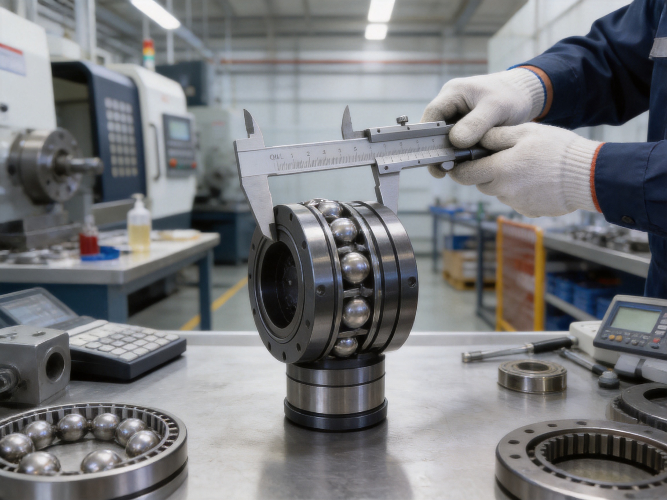
Strict quality control is especially important for constant-velocity couplings because the product’s performance depends on coordinated geometry rather than on a single easily measured dimension. Inspection may include dimensional verification, bore and keyway measurement, concentricity checks, raceway profile inspection, surface finish evaluation, hardness testing, assembly inspection, and rotational testing.
Testing facilities support the verification of product quality before delivery. Depending on the order and application, customers may request inspection records, material certificates, dimensional reports, balancing information, or other technical documents.
The company identifies ISO 9001 and related international standards and certifications among its quality commitments. A documented quality-management approach helps establish repeatable procedures for purchasing, production, inspection, nonconformance control, traceability, and customer service.
6.5 Custom manufacturing capability
Industrial equipment frequently requires non-standard shaft bores, special lengths, unusual connection details, altered materials, protective coatings, modified lubrication systems, or mounting arrangements adapted to existing machinery. The company undertakes the design and manufacture of non-standard couplings to address these needs.
Customization begins with collecting the operating data: torque, speed, angle, axial movement, shaft diameter, duty cycle, environmental conditions, installation space, and connection details. Engineering review then determines whether an existing model can be modified or whether a new configuration is required.
A customized design should be validated through drawings, calculations, manufacturing review, and agreed inspection requirements. Clear communication between the customer and manufacturer is essential, particularly when the coupling is intended to replace an existing product or integrate into a complex machine.
7. Installation Recommendations
Correct installation is necessary to obtain the benefits of the QWL coupling. Even a precisely manufactured coupling can experience premature wear if it is forced into position, contaminated, overloaded, or operated beyond its angular and axial limits.
7.1 Prepare the shafts and mounting area
Inspect the shafts for burrs, corrosion, dents, excessive runout, and incorrect dimensions. Confirm that the shaft diameter and keyway correspond to the approved drawing. Clean the shaft surfaces and coupling bores before assembly.
Check the mounting space and ensure that the coupling can be installed without striking adjacent components. The coupling should be supported during handling so that the cage and rolling elements are not subjected to impact loads.
7.2 Verify alignment and reference length
Although the QWL coupling compensates for angular movement, the connected machinery should still be aligned as accurately as practical. Excessive initial misalignment can increase contact forces and reduce the available movement margin.
Set the coupling to the specified reference length. Check the shaft center distance, angular position, and any required axial pre-positioning. If the coupling operates through a machine stroke, verify the complete range of movement rather than checking only one static position.
7.3 Tighten fasteners correctly
Bolts, keys, locking components, and other fastening parts should be installed according to the approved drawing and torque requirements. Fasteners should be clean and free of damaged threads. Uneven tightening may distort the assembly or produce an unbalanced rotating condition.
After tightening, rotate the assembly by hand where possible to confirm that it moves freely and does not contact surrounding components. Any abnormal resistance, binding, or noise should be investigated before commissioning.
7.4 Lubricate and protect the coupling
Use the specified lubricant and fill quantity. The lubricant must be compatible with the rolling contacts, seals, operating temperature, and environmental conditions. Over-lubrication can also be undesirable because it may increase churning and temperature.
Install protective guards where required by machinery safety regulations. The guard should prevent accidental contact with rotating components without restricting the coupling’s movement or causing heat accumulation.
8. Maintenance and Service Life
The QWL coupling is designed for reliable industrial operation, but regular inspection remains important. Maintenance intervals depend on speed, torque, angle, contamination, temperature, duty cycle, and the consequences of failure.
8.1 Routine inspection
Inspect the coupling for unusual noise, vibration, heat, grease leakage, loosened fasteners, corrosion, and visible damage. Changes in vibration or operating temperature may indicate wear, insufficient lubrication, excessive angle, axial overtravel, or a problem elsewhere in the drive train.
Check that the coupling guard has not shifted and that no foreign material has entered the assembly. In rolling mill, mining, and port applications, inspection may need to be more frequent because dust, scale, water, and impact loading can accelerate contamination and wear.
8.2 Lubrication management
Follow the recommended lubrication schedule and use the specified lubricant grade. Lubricant condition can be affected by water ingress, metal particles, high temperature, and chemical contamination. If the application is critical, lubricant sampling or periodic replacement may be included in the maintenance plan.
8.3 Rechecking alignment
Machine foundations can settle, bearings can wear, and connected structures can move over time. Recheck alignment after major maintenance, bearing replacement, a collision, or any change in operating vibration. Confirm that the shaft angle and axial position remain within the coupling’s limits.
8.4 Replacement planning
Replacement intervals should be based on inspection results, operating hours, load history, and manufacturer recommendations. When a coupling is removed, inspect the balls, cage windows, raceways, bores, keys, seals, and fastening components. Reusing damaged or heavily worn parts can compromise the performance of the complete assembly.
9. Safety and Reliability Considerations
Rotating couplings can cause serious injury if they are exposed during operation. A suitable guard should be installed, and personnel should not approach the coupling while the machine is running. Lockout and isolation procedures must be followed before inspection, lubrication, or adjustment.
The coupling should not be used as a substitute for a torque limiter unless it has been specifically designed and rated for that function. If the machine requires overload disconnection, a separate safety coupling or torque-limiting device may be installed in the drive system.
Engineering calculations should consider the failure consequences of the application. Critical equipment may require redundant support, condition monitoring, controlled startup, emergency braking analysis, and a defined inspection strategy. The product’s overload capability is limited to the specified short-term conditions and does not eliminate the need for correct system design.
10. Why Work with an Integrated Coupling Manufacturer?
An integrated manufacturer can support the complete coupling lifecycle, from initial selection to replacement and custom redesign. This is particularly important when the coupling must fit an existing machine or when the operating conditions differ from standard catalog assumptions.
Zhongye Heavy Industry Technology (Zhenjiang) Co., Ltd. provides engineering consultation, standard coupling supply, non-standard design, manufacturing, inspection, and after-sales technical support. Its product range covers multiple coupling technologies, allowing the engineering team to compare elastic, non-elastic, rigid, safety, and customized options.
The company’s location in Zhenjiang, Jiangsu Province, supports access to industrial manufacturing resources and transportation networks. Its workshop arrangement, precision production capability, testing facilities, quality procedures, and experienced technical personnel are intended to provide consistent products for customers in China and international markets.
For customers selecting the QWL series, technical discussions can cover shaft drawings, installation dimensions, torque calculations, angular requirements, operating speed, lubrication, environmental conditions, and delivery documentation. Early engineering communication helps prevent errors in bore selection, coupling length, mounting details, and service-factor calculation.
11. Practical Selection Example
Consider a conveyor drive that requires 2,000 N·m of calculated operating torque and experiences frequent starts with moderate shock loading. The connected shafts operate at an angular inclination, and the installation requires a shaft bore of approximately 70 mm.
The QWL5 model has a nominal torque rating of 2,240 N·m, but selecting it solely because its nominal rating is close to the calculated torque would provide limited margin. After applying a service factor for starting and shock loading, the required design torque may exceed the QWL5 rating. The QWL6 or QWL7 model may therefore be more appropriate, subject to speed, space, bore, and axial movement requirements.
If the operating angle is 17°, QWL5, QWL6, and QWL7 may provide the required angular capacity because their listed maximum inclination angle is 18°. However, continuous operation close to the limit should be reviewed carefully. A larger model may offer additional structural margin, but it will also increase mass, inertia, and installation requirements.
This example shows why coupling selection should consider the complete operating profile. Torque, angle, bore, length, speed, overload, environment, and dynamic response must be evaluated together.
12. Frequently Asked Questions
Q1. What type of coupling is the QWL series?
The QWL series is a flexible universal coupling with non-elastic transmission elements. It uses precision steel balls, a retaining cage, and raceways rather than an elastomeric insert or a conventional cross-shaped joint.
Q2. What is the main advantage of the ball cage design?
The main advantage is constant-velocity transmission during angular operation. The coupling is designed to maintain synchronized rotation between the driving and driven shafts while accommodating a specified shaft inclination.
Q3. What torque range is available?
The listed nominal torque range is from 180 N·m for QWL1 to 10,000 N·m for QWL9. The correct model depends on design torque, service factor, speed, angle, bore, and operating environment.
Q4. What is the maximum allowable shaft angle?
The maximum listed shaft inclination is approximately 16° to 20%, depending on the model. QWL1 and QWL2 are listed at 16°, QWL3 through QWL7 at 18°, and QWL8 and QWL9 at 20°.
Q5. Can the coupling accommodate axial movement?
Yes. The product data includes length extension and contraction allowances. The actual permitted movement depends on the model and configuration, and it must remain within the specified technical limits.
Q6. Is the QWL coupling suitable for high-shock applications?
It can be suitable for applications involving short-term overload and impact, provided the coupling is selected using the correct service factor. The technical information states that short-term overload torque may reach three times nominal torque for no more than 15 seconds. Repeated or continuous overload requires separate evaluation.
Q7. Does the coupling require lubrication?
Rolling contact systems normally require appropriate lubrication to control friction, heat, and wear. The recommended lubricant, filling method, sealing arrangement, and maintenance interval should be confirmed for the selected model and operating environment.
Q8. Can the QWL coupling replace a gear coupling?
It may replace a gear coupling in applications where its torque, speed, angle, axial movement, dimensions, and environmental capabilities are suitable. A direct replacement should not be assumed without checking the complete operating requirements.
Q9. Is customization available?
Yes. The manufacturer undertakes non-standard coupling design and manufacturing. Possible customization areas include bore size, length, shaft connection, material, surface treatment, lubrication, sealing, and installation configuration, subject to engineering review.
Q10. What information should be provided for a quotation?
Useful information includes motor power, operating speed, normal and peak torque, startup and braking conditions, shaft diameters, keyway details, shaft angle, axial movement, installation length, ambient temperature, contamination, duty cycle, and required quantity.
Q11. Is the coupling appropriate for precision machinery?
Its constant-velocity characteristics make it appropriate for selected precision applications, including certain machine-tool and conveyor systems. High-speed or ultra-precision use requires additional review of balance, inertia, vibration, lubrication, and installation accuracy.
Q12. How does the manufacturer support quality?
The manufacturer integrates research and development, production, inspection, and technical service. Its facilities include heavy and precision workshops, testing capabilities, quality-control procedures, and support for standard and customized coupling products.
13. Conclusion
The QWL Type Ball Cage Universal Coupling provides a specialized solution for industrial power transmission where angular flexibility and constant-velocity rotation are both required. Its precision steel balls, retaining cage, and symmetrical raceways create a rolling transmission path that differs fundamentally from conventional cross-shaft universal couplings, elastic couplings, gear couplings, and rigid couplings.
With nominal torque ratings from 180 N·m to 10,000 N·m, shaft inclination capacities from 16° to 20°, multiple bore options, and controlled axial movement, the series can serve a broad range of machinery. Metallurgical roller tables, CNC-related drive systems, precision conveyors, construction machinery, mining equipment, lifting systems, paper machinery, and port equipment can all benefit when the coupling is correctly selected and installed.
The product’s value is supported by the manufacturer’s integrated capabilities. Research and development, precision manufacturing, heavy-duty production facilities, testing resources, quality management, customization support, and after-sales engineering assistance provide a complete foundation for industrial coupling supply.
Successful application depends on more than choosing a nominal torque rating. Engineers should evaluate peak torque, speed, angle, axial movement, inertia, environment, lubrication, installation length, service factor, and maintenance access. With this complete approach, the QWL series can provide stable, synchronized, and durable transmission for demanding mechanical systems.
References
1. Manufacturer-provided technical data for the QWL Type Ball Cage Universal Coupling, including torque ratings, shaft inclination limits, bore dimensions, axial movement data, inertia values, and mass data.
2. Manufacturer-provided product and company information for Zhongye Heavy Industry Technology (Zhenjiang) Co., Ltd., including manufacturing facilities, product categories, quality management, customization capability, and application sectors.
3. General engineering principles for flexible coupling selection, shaft alignment, torque calculation, service factors, lubrication, and rotating equipment safety.
4. General design principles for constant-velocity joints, rolling-element torque transmission, universal couplings, and angularly misaligned shaft systems.
5. ISO 9001 quality-management principles as referenced in the manufacturer’s quality and certification information.
Product: QWL Type Ball Cage Universal Coupling

- Quick Links
- About
- Products
- Our Service
- News & Events
- Contact
- Products Series
- Flexible Couplings with Non-Elastic Elements
- Flexible Couplings with Metal Elastic Elements
- Flexible Couplings with Non-Metallic Elastic Elements
- Safety Coupling
- Rigid Coupling
- Contact Us
- Tel : +86 511 8572 3800 +86 511 8572 3900
- Mobile : +86 15106109009
- Email : sales@couplingzy.com
- Add:No.1 Zhongye Yingbin Avenue, Gaozi Street, Dantu Economic Development Zone, Zhenjiang City, Jiangsu Province, China.


