:+86 15106109009
:sales@couplingzy.com


 English
  русский
  Español
  عربى
عربى  Português
  Deutsch
  Türk
Türk  Indonesia

Engineering Guide to SWC-WH Non-Expansion Welded Universal Couplings
Content
- 1 1. Product Function and Operating Principle
- 2 2. Main Design Characteristics
- 3 3. Performance Range and Model Selection
- 4 4. Key Dimensional and Connection Data
- 5 5. Advantages Compared with Alternative Coupling Types
- 6 6. Manufacturing Strengths and Quality Approach
- 7 7. Industrial Applications
- 8 8. Installation Considerations
- 9 9. Maintenance and Service Practices
- 10 10. How to Specify the Correct Coupling
- 11 11. Customization and Non-Standard Engineering
- 12 12. Company Manufacturing and Service Advantages
- 13 13. Practical Comparison of Product Benefits
- 14 14. Limitations and Selection Boundaries
- 15 15. Recommended Procurement Process
- 16 16. Frequently Asked Questions
- 16.1 What is the SWC-WH coupling used for?
- 16.2 What does “non-expansion” mean?
- 16.3 Is the SWC-WH an elastic coupling?
- 16.4 What is the available torque range?
- 16.5 What is the maximum shaft angle?
- 16.6 Can it replace a rigid coupling?
- 16.7 Can it replace an elastomeric coupling?
- 16.8 Does the coupling require maintenance?
- 16.9 Can the coupling be customized?
- 16.10 What information is needed for a quotation?
- 16.11 Where is the product manufactured?
- 16.12 What industries can use the product?
- 17 17. Conclusion
- 18 References
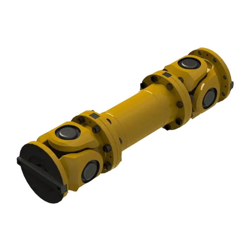
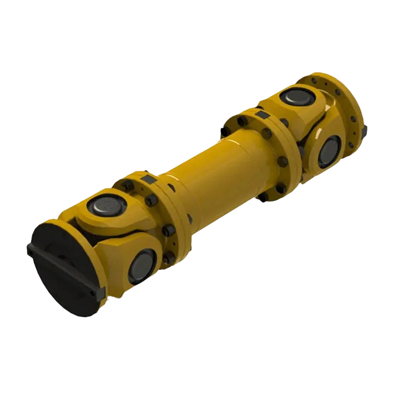
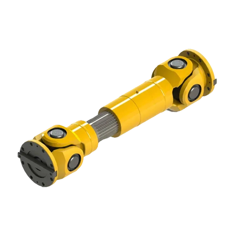
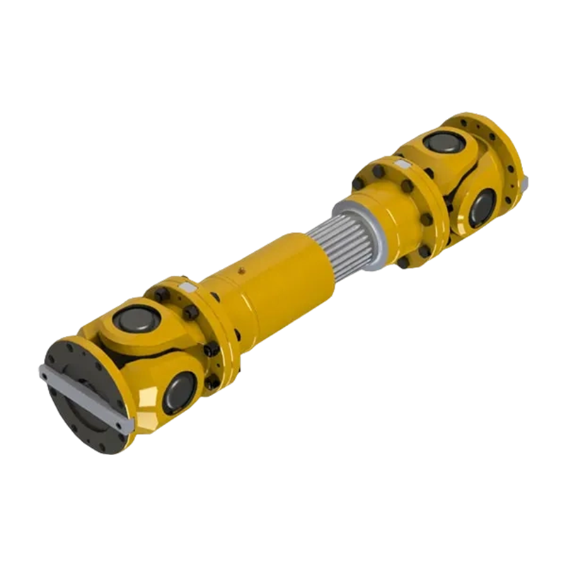
- 19 Product: SWC-WH type non-expansion welded universal coupling
Reliable torque transmission is essential in heavy industrial machinery. In rolling mills, mining conveyors, lifting systems, port equipment, paper machines, water equipment, and other demanding applications, the coupling between two shafts must transmit power while accommodating unavoidable angular misalignment. If the coupling cannot tolerate shaft-angle variation, mechanical stresses can concentrate in bearings, gearboxes, shafts, and connected equipment. If its structure is unnecessarily complicated, installation and maintenance can become expensive and time-consuming.
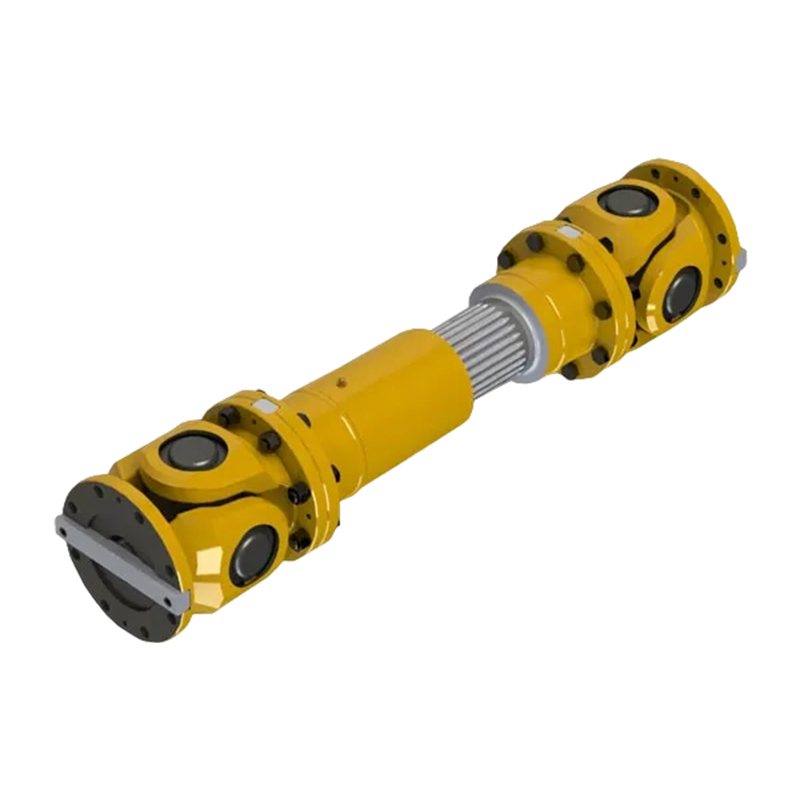
The SWC-WH type non-expansion welded universal coupling is designed to address these requirements through a simple welded construction and a universal-joint transmission arrangement. It belongs to the category of flexible couplings with non-elastic elements. Unlike couplings that use rubber, polyurethane, or other elastic components to absorb misalignment, the SWC-WH transfers torque through mechanical universal-joint components while allowing angular movement between connected shafts.
This coupling is intended for applications that require angular misalignment compensation but do not require axial displacement compensation or adjustment for thermal expansion. Its non-expansion design provides a stable and direct connection for systems in which the relative axial position of the shafts remains essentially fixed during operation.
With nominal torque capacities ranging from 2.5 kN·m to 1,000 kN·m and rotation diameters from 100 mm to 550 mm, the series covers a broad range of industrial transmission duties. Depending on the selected model, the permissible shaft angle is up to 25 degrees for the smaller sizes and up to 15 degrees for the larger sizes. This combination of high torque capability, angular flexibility, and compact welded construction makes the coupling suitable for heavy-duty machinery requiring dependable continuous power transmission.
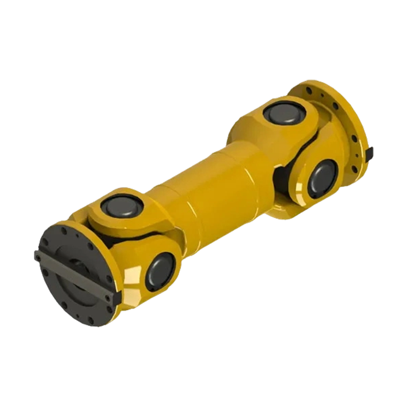
SWC-WH type non-expansion welded universal coupling
1. Product Function and Operating Principle
A coupling connects a driving shaft to a driven shaft and transfers rotational power from one machine to the other. In a practical industrial installation, however, the two shafts are rarely perfectly aligned. Manufacturing tolerances, foundation settlement, thermal effects, bearing clearances, assembly conditions, and structural deflection can all create a difference in shaft centerlines or shaft angles.
The SWC-WH coupling is designed primarily to compensate for angular misalignment. Its universal-joint configuration permits the connected shafts to operate at an angle while still transmitting torque. The joint components articulate during rotation, allowing the coupling to follow the relative shaft angle rather than forcing both shafts into a perfectly straight line.
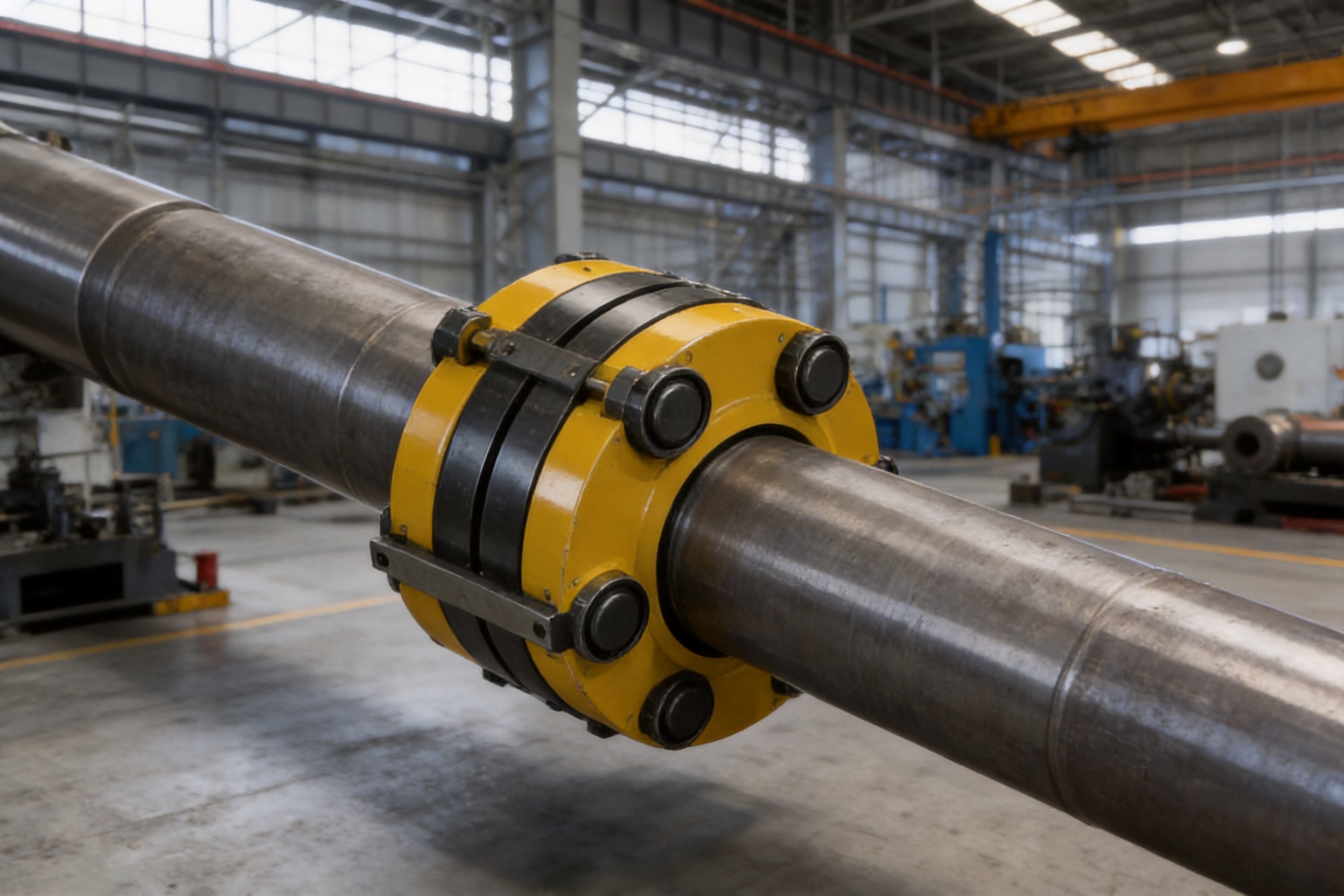
The welded construction forms a rigid and durable body around the universal-joint transmission arrangement. Welding reduces the number of detachable structural interfaces and creates a stable connection between major components. This is particularly valuable for applications where the coupling must endure repeated torque reversals, vibration, impact loading, and demanding operating cycles.
As a non-expansion coupling, the SWC-WH does not provide designed axial movement for thermal expansion. This feature should be understood during system design. The connected equipment should be arranged so that axial thermal movement is either insignificant, controlled by the machine structure, or handled by another component in the transmission system. When the application does not require axial compensation, the non-expansion design can provide a straightforward and efficient solution.
Torque transmission through mechanical elements
Mechanical universal couplings transmit torque through metallic load-bearing components rather than through flexible rubber or polymer elements. This gives the coupling a direct load path and makes it suitable for high torque applications. The absence of an elastic insert also eliminates the need to monitor the service life of a rubber element that could harden, crack, age, or lose resilience.
The coupling nevertheless remains flexible in the required direction because the universal-joint geometry permits angular articulation. This is different from a rigid flange coupling, which requires a much higher degree of alignment accuracy. The SWC-WH therefore occupies an important position between rigid couplings and highly flexible elastic couplings.
Angular misalignment capability
The stated shaft-angle capability is up to 25 degrees for SWC100WH, SWC120WH, and SWC150WH. For models from SWC180WH through SWC550WH, the listed maximum angle is up to 15 degrees. These values describe the permissible angular relationship under the specified operating conditions and should not be interpreted as a substitute for correct shaft alignment.
Correct alignment remains important because excessive misalignment can increase bearing loads, joint wear, vibration, and operating temperature. The universal joint compensates for a planned angular relationship; it should not be used to correct poor installation or uncontrolled structural movement.
2. Main Design Characteristics
Welded construction
The welded design is one of the defining characteristics of the SWC-WH series. A welded coupling can have fewer bolted structural connections than a split or extensively assembled design. This simplifies the overall construction and reduces the possibility of loosening at unnecessary interfaces.
Welding also supports the manufacture of a compact body with a favorable strength-to-size relationship. When the welds are correctly designed, prepared, executed, and inspected, the structure can provide high resistance to operating loads. For heavy industrial machinery, this is a practical advantage because the coupling must often fit into confined spaces while transmitting substantial torque.
The welding process must be controlled carefully. Material preparation, joint fit-up, welding sequence, heat input, distortion control, and post-weld inspection all influence the final quality. A professional manufacturer should maintain documented welding procedures and ensure that the completed structure meets dimensional and mechanical requirements.
Universal-joint configuration
The universal-joint arrangement permits the coupling to transmit torque between shafts that are not collinear. This provides a useful solution for equipment layouts in which the drive and driven machines cannot be positioned on a common straight centerline.
Universal joints also allow a relatively large angular displacement compared with many conventional elastic couplings. This can reduce the need for complex supporting structures or extensive corrective machining. The exact operating angle, speed, torque, and duty cycle must still be evaluated together because a coupling operating at a high angle and high speed may experience different loads from one operating at a small angle and low speed.
Non-elastic flexibility
The SWC-WH is classified as a flexible coupling with a non-elastic element. Its flexibility comes from articulated metallic geometry rather than from the deformation of an elastomer. This distinction has several practical consequences.
First, the coupling is not dependent on the temperature range, aging behavior, or chemical resistance of a rubber element. Second, it can be suited to high torque transmission where an elastomeric element would need to be very large or would experience excessive deformation. Third, its torsional response is more direct because there is no soft elastic insert intentionally placed in the torque path.
At the same time, the coupling does not provide the same inherent damping characteristics as a rubber or polyurethane coupling. If the drive system has severe torsional vibration, frequent shock loading, or resonance concerns, the complete drivetrain should be analyzed before selection. The correct coupling depends on the total mechanical system, not only on the nominal torque value.
Fixed axial relationship
The non-expansion design maintains the axial relationship between the connected shafts. This is useful when the machine arrangement requires a stable shaft position and when thermal expansion is not expected to create a significant axial movement problem.
During design, engineers should identify which component will accommodate any axial changes in the system. The coupling should not be expected to perform a function that it was not designed to provide. If substantial axial displacement is required, an expansion-type universal coupling or another suitable axial-compensating solution should be considered.
3. Performance Range and Model Selection
The SWC-WH series includes fourteen listed sizes, from SWC100WH to SWC550WH. The rotation diameter increases progressively through the range, as does the nominal torque capacity. This allows the coupling to be selected according to the actual power-transmission requirement rather than forcing every installation to use a large, heavy model.
| Model | Rotation Diameter D (mm) | Nominal Torque Tn (kN·m) | Fatigue Torque Tf (kN·m) | Maximum Axis Angle (°) | Mass, Minimum Length (kg) | Mass Increase per 100 mm (kg) |
| SWC100WH | 100 | 2.5 | 1.25 | 25 | 4.5 | 0.35 |
| SWC120WH | 120 | 5 | 2.5 | 25 | 7.7 | 0.55 |
| SWC150WH | 150 | 10 | 5 | 25 | 18 | 0.85 |
| SWC180WH | 180 | 22.4 | 11.2 | 15 | 48 | 2.8 |
| SWC200WH | 200 | 36 | 18 | 15 | 72 | 3.7 |
| SWC225WH | 225 | 56 | 28 | 15 | 78 | 4.9 |
| SWC250WH | 250 | 80 | 40 | 15 | 124 | 5.3 |
| SWC285WH | 285 | 120 | 58 | 15 | 185 | 6.3 |
| SWC315WH | 315 | 160 | 80 | 15 | 262 | 8 |
| SWC350WH | 350 | 225 | 110 | 15 | 349 | 11.5 |
| SWC390WH | 390 | 320 | 160 | 15 | 506 | 15 |
| SWC440WH | 440 | 500 | 250 | 15 | 790 | 21.7 |
| SWC490WH | 490 | 700 | 350 | 15 | 1,104 | 27.3 |
| SWC550WH | 550 | 1,000 | 500 | 15 | 1,526 | 34 |
The table shows the relationship between size, torque capacity, and weight. The smallest model has a nominal torque of 2.5 kN·m, while the largest reaches 1,000 kN·m. The range makes the series suitable for both relatively compact industrial drives and very high-load equipment.
Nominal torque
Nominal torque is the principal starting point for model selection. The operating torque of the machine should be calculated from motor power and rotational speed, with appropriate consideration of starting conditions, acceleration, overloads, impact loads, reversing operation, and duty cycle.
A basic relationship between power, speed, and torque is commonly expressed as:
Torque in N·m = 9,550 × Power in kW ÷ Speed in r/min.
This calculation provides an operating torque estimate. The selected coupling should then be checked against the manufacturer's nominal torque rating and any applicable service factor. Applications with heavy starting loads, frequent starts and stops, reversing, or severe impact may require a larger size even when the average running torque appears acceptable.
Fatigue torque
The listed fatigue torque is an important reference for applications involving repeated cyclic loading. It should be considered when the coupling experiences fluctuating torque, vibration, reversing loads, or a high number of operating cycles.
For many models, the fatigue torque is approximately half the nominal torque, although the values should always be taken from the individual model specification. Designers should not assume that a coupling rated for a certain nominal torque will have the same allowable value under every fatigue condition. The actual service environment and loading pattern must be reviewed.
Rotation diameter
The rotation diameter affects the installation envelope, guard design, peripheral speed, and available space around the coupling. A larger rotation diameter generally corresponds to a greater torque capacity, but it also increases the required safety guard dimensions and may affect the mass and inertia of the drivetrain.
Before final selection, engineers should verify the available radial clearance, the distance between adjacent machine components, access for maintenance, and the ability to install or remove the coupling without dismantling unnecessary equipment.
Length and shaft arrangement
The catalog data includes a minimum length and an increase in mass for each additional 100 mm of length. This enables the coupling to be adapted to different shaft spacing requirements. The required length should be defined from the actual distance between shaft ends and the connection geometry of the equipment.
Longer couplings may have higher mass and rotational inertia. This can influence acceleration, braking, bearing loads, and torsional behavior. The shaft extension, support arrangement, and operating speed should therefore be reviewed together with the selected coupling length.
4. Key Dimensional and Connection Data
The SWC-WH specification includes several dimensional parameters for each model. These include D1, D2, D3, Lm, bolt-circle information represented by n × φd, and additional dimensions identified as k, t, b, and g. These dimensions are essential for checking compatibility with the connected shafts and machine flanges.
| Model | Lmin (mm) | D1 (mm) | D2 (mm) | D3 (mm) | Lm (mm) | Connection |
| SWC100WH | 243 | 84 | 57 | 60 | 55 | 6 × φ9 |
| SWC120WH | 307 | 102 | 75 | 70 | 65 | 8 × φ11 |
| SWC150WH | 350 | 130 | 90 | 89 | 80 | 8 × φ13 |
| SWC180WH | 480 | 155 | 105 | 114 | 110 | 8 × φ17 |
| SWC200WH | 500 | 170 | 120 | 133 | 115 | 8 × φ17 |
| SWC225WH | 520 | 196 | 135 | 152 | 120 | 8 × φ17 |
| SWC250WH | 620 | 218 | 150 | 168 | 140 | 8 × φ19 |
| SWC285WH | 720 | 245 | 170 | 194 | 160 | 8 × φ21 |
| SWC315WH | 805 | 280 | 185 | 219 | 180 | 10 × φ23 |
| SWC350WH | 875 | 315 | 210 | 245 | 194 | 10 × φ23 |
| SWC390WH | 955 | 340 | 235 | 267 | 215 | 10 × φ25 |
| SWC440WH | 1,155 | 390 | 255 | 325 | 260 | 16 × φ28 |
| SWC490WH | 1,205 | 435 | 275 | 351 | 270 | 16 × φ31 |
| SWC550WH | 1,355 | 492 | 320 | 426 | 305 | 16 × φ31 |
The connection dimensions must be matched with the mating flanges, shaft ends, key arrangements, and fastening hardware. D2 is identified with an H7 tolerance in the specification, while D1 is identified with a js11 tolerance and b with an h9 tolerance. These tolerance designations indicate that the fit and dimensional control of the connection are important to the performance of the assembly.
Customers should provide complete shaft and machine-interface drawings when requesting a quotation or customized version. Important information includes shaft diameter, shaft length, keyway dimensions, flange dimensions, bolt pattern, operating speed, shaft angle, installation space, and environmental conditions.
5. Advantages Compared with Alternative Coupling Types
Compared with rigid couplings
Rigid couplings provide a strong and direct connection, but they require the connected shafts to be aligned with a high degree of accuracy. Even a small angular error can produce additional loads on bearings and shafts. Rigid couplings are therefore most appropriate where the two shafts are permanently aligned and supported by a common structure.
The SWC-WH offers a significant advantage where angular misalignment is unavoidable. Its universal-joint mechanism permits the shafts to operate at an angle while continuing to transmit torque. This can reduce alignment sensitivity and make the coupling more appropriate for large machines with separate foundations or complex mechanical layouts.
The comparison is not a claim that a universal coupling is always superior. A rigid coupling may be more suitable for a short, accurately aligned shaft connection. The advantage of the SWC-WH appears when the application requires both high torque transmission and angular flexibility.
Compared with elastomeric couplings
Elastomeric couplings can provide useful vibration damping and may compensate for angular, parallel, and axial misalignment depending on their design. However, the elastic element can be affected by temperature, oil, chemicals, ultraviolet exposure, aging, fatigue, and excessive deformation.
The SWC-WH avoids dependence on a rubber or polymer element. Its metallic transmission path is appropriate for high torque and demanding industrial environments in which an elastic insert could have a shorter service life. The coupling also avoids routine replacement of a flexible insert when that insert is the primary wear component.
On the other hand, elastomeric couplings may be preferable when torsional damping and electrical insulation are important. The final choice should therefore be based on the application requirements rather than on a single performance characteristic.
Compared with gear couplings
Gear couplings can transmit high torque in a relatively compact envelope and may compensate for certain types of misalignment. They normally depend on meshing gear teeth and lubrication. Tooth wear, lubricant contamination, seal degradation, and maintenance access must be considered.
The SWC-WH provides angular compensation through a universal-joint structure rather than through external gear-tooth engagement. This may be advantageous in applications where the required shaft angle is relatively large or where a universal-joint arrangement is more compatible with the equipment layout.
Compared with diaphragm and disc couplings
Diaphragm and disc couplings offer low backlash, torsionally stiff performance, and compensation for selected types of misalignment. Their flexibility is created by thin metallic discs or diaphragms that operate under repeated deformation. These couplings are often selected for high-speed precision machinery.
The SWC-WH is more strongly oriented toward high-load industrial machinery and significant angular articulation. Its welded universal construction is especially suitable when the priority is robust torque transmission, structural simplicity, and reliable operation in heavy-duty environments rather than extremely low backlash or high-speed precision.
6. Manufacturing Strengths and Quality Approach
The performance of a universal coupling depends not only on its design calculations but also on the quality of its manufacturing process. A coupling may be subjected to high torque, cyclic loading, impact, vibration, and misalignment. Inadequate material quality, weld defects, poor machining, or incorrect assembly can reduce its service life even when the nominal design is appropriate.
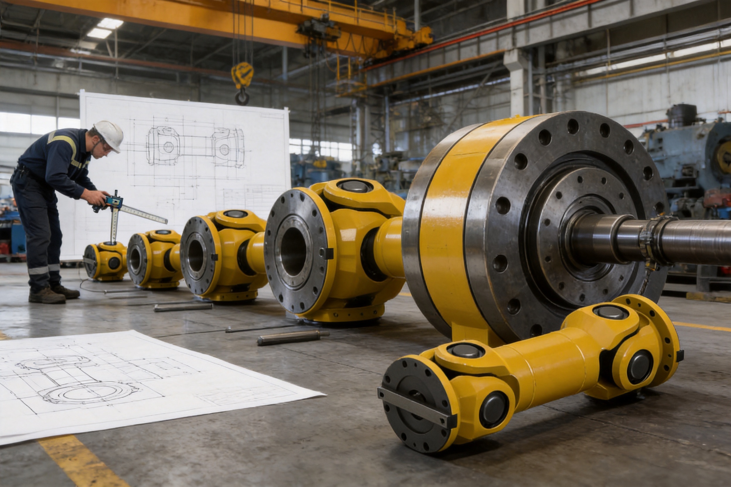
Zhongye Heavy Industry Technology (Zhenjiang) Co., Ltd. integrates research and development, manufacturing, and sales. Its production capabilities are supported by a new workshop area of approximately 16,463.52 square meters. The facility includes a heavy workshop of about 5,500 square meters, a precision workshop of approximately 4,600 square meters, an office building and gymnasium, a dining hall, a warehouse, and supporting roads, green areas, and parking spaces.
Heavy fabrication capability
The heavy workshop supports the manufacture and handling of large coupling components. Large universal couplings require stable fixtures, lifting capability, welding access, and sufficient floor space. A dedicated heavy-production environment helps the manufacturer manage large diameters, long lengths, and high component weights more effectively than a small general-purpose workshop.
Heavy fabrication also requires attention to distortion control. Welded parts can change shape as heat is introduced and removed. Controlled welding sequences, appropriate clamping, dimensional checks, and corrective procedures help ensure that the finished coupling remains within the required geometry.
Precision machining
The precision workshop supports machining of bores, flange faces, bolt holes, keyways, bearing seats, and other critical interfaces. Dimensional precision is important because inaccurate mating surfaces can create eccentricity, imbalance, uneven loading, or installation difficulties.
The specification includes tolerance classes for selected dimensions, demonstrating that the connection areas are not treated as rough structural surfaces. Accurate machining helps ensure that the coupling can be fitted to the customer's shafts and flanges with predictable results.
Research and development
A coupling manufacturer with research and development capability can adapt product geometry to different torque levels, shaft angles, installation lengths, and customer interfaces. This is particularly important for non-standard industrial machinery, where a standard catalog size may not directly match the available space or shaft arrangement.
Product development should include mechanical analysis, material evaluation, stress assessment, fatigue considerations, joint design, dimensional verification, and prototype or sample testing. Engineering experience across several coupling families also helps the manufacturer recommend a product type that matches the actual duty rather than simply supplying the largest available model.
Testing and quality control
Quality control should cover incoming materials, weld preparation, welding operations, heat-affected areas, machining, dimensions, surface condition, assembly, and final inspection. Depending on the project requirements, inspections may include dimensional measurement, visual weld inspection, non-destructive testing, hardness checks, balancing, and functional verification.
The company states that it maintains advanced testing facilities, strict quality control, complete specifications, and production guarantees. Its products comply with international standards and certifications such as ISO 9001. These systems support consistent manufacturing and provide a framework for traceability and process improvement.
For critical applications, purchasers should request the inspection and documentation package applicable to the order. Such documentation may include material certificates, dimensional reports, welding records, non-destructive testing reports, balancing records, and final inspection certificates.
7. Industrial Applications
Metallurgical equipment
Metallurgical machinery often operates under high loads, shock conditions, elevated temperatures, dust, and frequent starting or reversing cycles. Rolling mills, straightening machines, transfer equipment, and other steel-processing systems may have shafts that are separated by significant distances or arranged at an angle.
The SWC-WH is well suited to this type of environment because its metallic transmission structure is appropriate for high torque and repeated industrial duty. The welded body can provide a robust connection, while the universal joint accommodates the angular relationship between shafts.
Mining equipment
Mining machinery commonly experiences impact loads, vibration, abrasive dust, variable material flow, and difficult maintenance conditions. Conveyors, crushers, feeders, hoists, and processing equipment may require a coupling with high torque capacity and a durable mechanical structure.
The broad SWC-WH torque range allows engineers to select a model for different classes of mining equipment. The coupling should be protected by a suitable guard and included in a planned inspection program, especially where dust and contamination may affect bearings or joint components.
Material-handling equipment
Material-handling systems include conveyors, transfer tables, lifting mechanisms, stackers, reclaimers, and port machinery. These systems may have long shaft arrangements and moving structures that create angular changes during operation.
A universal coupling can simplify the drivetrain layout by allowing a controlled angle between the drive and driven shafts. The non-expansion version is especially appropriate where the shaft spacing remains fixed and axial movement is not a primary requirement.
Water equipment
Pumps, water-treatment machinery, gates, mixers, and other water equipment may require durable shaft connections in environments where humidity and corrosion protection are important. The coupling material, coating, seals, and maintenance plan should be selected according to the water quality and surrounding atmosphere.
The SWC-WH can be integrated into water equipment when the required torque, speed, shaft angle, and axial conditions are compatible with its design. Protective finishing and appropriate bearing maintenance are important for long-term service.
Paper equipment
Paper machinery includes numerous rotating systems, rolls, conveyors, and processing units. Some sections require accurate speed transmission, while others operate under variable loads and continuous production conditions.
When a paper-machine drive requires a strong angularly flexible connection, the SWC-WH can provide a practical alternative to a rigid shaft arrangement. Installation cleanliness and alignment verification are especially important because paper production environments may contain moisture, fibers, chemicals, and restricted maintenance access.
Port and lifting equipment
Port machinery and lifting equipment often experience starting shocks, braking loads, reversing operation, and fluctuating torque. Cranes, hoists, transfer systems, and ship-loading equipment require careful selection based on dynamic service factors.
The coupling's fatigue torque rating should be considered alongside the actual operating cycle. A design review should include acceleration torque, brake torque, emergency stopping, load swing, and any possible impact condition. In such applications, a coupling selected only from average running torque may be undersized.
Food-processing and general industrial equipment
The product information identifies food processing among the possible application fields. In these installations, hygiene, corrosion resistance, washdown conditions, and the presence of cleaning agents must be evaluated. A suitable surface treatment, material selection, guard design, and cleaning procedure should be confirmed for the specific production environment.
The coupling may also be used in general machinery where high torque and angular flexibility are required. Its suitability should be confirmed through an engineering review of speed, angle, load, environment, and installation conditions.
8. Installation Considerations
Correct installation is essential for obtaining the expected performance of any coupling. Before installation, all components should be checked for transport damage, corrosion, contamination, and dimensional conformity. Shaft ends and mating flanges should be clean, free from burrs, and prepared according to the approved assembly drawing.
Alignment verification
The shaft angle should be measured or established from the machine drawings. The actual operating angle must remain within the permissible value for the selected SWC-WH model. Although the coupling is designed to compensate for angular misalignment, the machine should still be aligned as accurately as the layout permits.
Angular alignment should be considered at the expected operating condition, not only when the machine is cold and unloaded. Foundation movement, thermal conditions, equipment weight, and bearing position can alter the relationship between shafts. Where necessary, alignment should be checked after commissioning and again during scheduled maintenance.
Connection and fastening
The mating bolt pattern must correspond to the selected coupling. Fasteners should be of the specified grade and installed using the required tightening method. Bolt seating surfaces should be clean and flat, and tightening should be performed in a controlled sequence to avoid distortion.
Keyed shaft connections, interference fits, or other interfaces must be prepared according to the approved design. Improper key dimensions, insufficient engagement, excessive clearance, or damaged shaft surfaces can cause fretting, backlash, and fatigue damage.
Installation length
The coupling length should be checked against the actual shaft-end distance. The minimum length shown in the product data is a reference for the standard configuration. If a longer coupling is required, the additional length and corresponding increase in mass should be included in the mechanical review.
There should be sufficient clearance for angular movement, lubrication access where applicable, inspection, and guard installation. No stationary structure should interfere with the rotating body at any expected operating angle.
Safety guarding
A rotating coupling must be enclosed by a suitable guard that prevents personnel contact and contains or limits hazards in the event of component failure. The guard should be structurally secure, properly ventilated where necessary, and removable for inspection without creating unnecessary risk.
The rotation diameter, operating speed, and coupling mass should be considered when designing the guard. Warning labels and lockout procedures should be used during inspection or maintenance.
9. Maintenance and Service Practices
The SWC-WH design is intended to simplify maintenance compared with some more complex coupling arrangements, but it is not maintenance-free. A planned inspection program helps identify wear, looseness, lubrication problems, corrosion, and alignment changes before they develop into major failures.
Routine inspection
Routine inspections should look for unusual noise, vibration, temperature rise, fretting marks, loosened fasteners, cracked welds, surface damage, and changes in the shaft angle. Any visible leakage or loss of lubricant from a bearing or joint area should be investigated promptly.
Inspection frequency should be based on operating hours, duty severity, speed, environmental contamination, starting frequency, and the consequences of failure. Heavy shock applications may require more frequent inspection than steady-duty applications.
Lubrication and bearings
Universal-joint bearings and related moving components require the lubrication specified for the particular design. The lubricant should be compatible with the operating temperature, speed, load, and surrounding environment. Over-lubrication can be as undesirable as insufficient lubrication because it may increase temperature or damage seals.
Lubrication intervals should be documented. In dusty, wet, or high-temperature environments, the recommended interval may need to be adjusted after consultation with the manufacturer. Contaminated lubricant should not be allowed to remain in service.
Wear and replacement
Wear should be evaluated at the joint, bearing, shaft interface, keyway, flange, and fastener locations. Excessive clearance can produce backlash and impact, while uneven wear may indicate misalignment, inadequate lubrication, or an overload condition.
Worn parts should be replaced with approved components. Welding, machining, or field modification of load-bearing parts should not be carried out without engineering authorization because changes can affect balance, strength, heat treatment, and fatigue performance.
Balancing and vibration
As coupling size and speed increase, balance becomes increasingly important. Vibration measurements can help identify imbalance, misalignment, bearing wear, looseness, or drivetrain resonance. A sudden change in vibration should be treated as a warning and investigated before continued operation.
Any repair that changes the mass distribution of a rotating component may require rebalancing. The balancing grade and test requirements should be agreed during the order stage for applications with elevated rotational speed or strict vibration limits.
10. How to Specify the Correct Coupling
A complete technical inquiry enables the manufacturer to confirm the correct model and identify any customization requirements. The following information should be prepared before selecting a coupling.
The first item is the transmitted power and operating speed. Motor power alone is not sufficient because torque depends on speed. The normal torque, peak torque, starting torque, braking torque, and reversing conditions should also be identified.
The second item is the shaft angle. The angle should be stated in degrees for both normal operation and any anticipated maximum condition. The selected model must remain within its specified angle limit.
The third item is the shaft and flange geometry. Shaft diameters, bore tolerances, keyways, shaft lengths, bolt circles, flange thicknesses, and the distance between shaft ends should be supplied in a dimensioned drawing.
The fourth item is the axial condition. The customer should confirm whether the shaft spacing remains fixed or changes during operation. If thermal expansion or machine movement produces significant axial displacement, the non-expansion SWC-WH may not be the correct version.
The fifth item is the environment. Temperature, moisture, dust, chemicals, washdown, corrosive atmosphere, outdoor exposure, and explosive-area requirements can affect material, coating, sealing, lubrication, and guard selection.
The sixth item is the duty cycle. Continuous operation, intermittent operation, frequent starts, shock loading, reversing, emergency stops, and variable-speed operation should all be described. These conditions influence service-factor selection and fatigue assessment.
The seventh item is installation and maintenance access. Available space, lifting equipment, removal direction, guard design, and inspection intervals should be considered before approving the coupling arrangement.
11. Customization and Non-Standard Engineering
Industrial equipment frequently requires a coupling that differs from a standard catalog arrangement. Shaft dimensions may not match standard bores, the available installation length may be unusual, the bolt pattern may be proprietary, or the operating angle may require special evaluation.
The manufacturer undertakes the design and manufacture of various non-standard couplings. This capability allows the standard SWC-WH concept to be adapted to customer-specific interfaces where appropriate. Customization may involve connection dimensions, length, bore arrangement, material, protective coating, balancing requirements, or other mechanical details.
Customization should begin with a complete set of technical data. A preliminary concept can be evaluated more accurately when the customer provides machine drawings, torque-speed curves, operating cycles, shaft loads, space limitations, environmental conditions, and applicable standards.
Engineering review is especially important when the requested design operates near the upper end of the torque range, at a large shaft angle, or under severe fatigue conditions. A customized coupling should be checked for strength, bearing life, fatigue, critical speed, balance, and installation practicality.
12. Company Manufacturing and Service Advantages
Zhongye Heavy Industry Technology (Zhenjiang) Co., Ltd. is based in Zhenjiang, Jiangsu Province, China, and integrates research and development, manufacturing, and sales. Its product range includes universal couplings as well as toothed couplings, elastic sleeve pin couplings, elastic pin couplings, gear couplings with elastic pins, tire couplings, jaw couplings, star couplings, diaphragm couplings, drum couplings, grid couplings, Oldham couplings, flange couplings, clip-shell couplings, roller-chain couplings, safety couplings, and other transmission products.
This broad product portfolio is valuable to industrial customers because different shafts and machines often require different coupling principles. A manufacturer experienced in several coupling categories can compare alternatives and recommend a suitable solution based on torque, misalignment, damping, axial movement, speed, environment, and maintenance requirements.
The company's stated strengths include strong research and manufacturing capabilities, advanced testing facilities, strict quality control, complete product specifications, customization support, high transmission efficiency, pre-sale technical assistance, non-standard design solutions, and after-sale service support.
These capabilities are particularly relevant to the SWC-WH series. A universal coupling is not selected by diameter alone. It must be matched to the shaft angle, torque spectrum, machine geometry, installation length, operating environment, and expected service life. Technical support before purchase can help prevent an incorrect selection, while after-sale assistance can support installation, commissioning, inspection, and replacement planning.
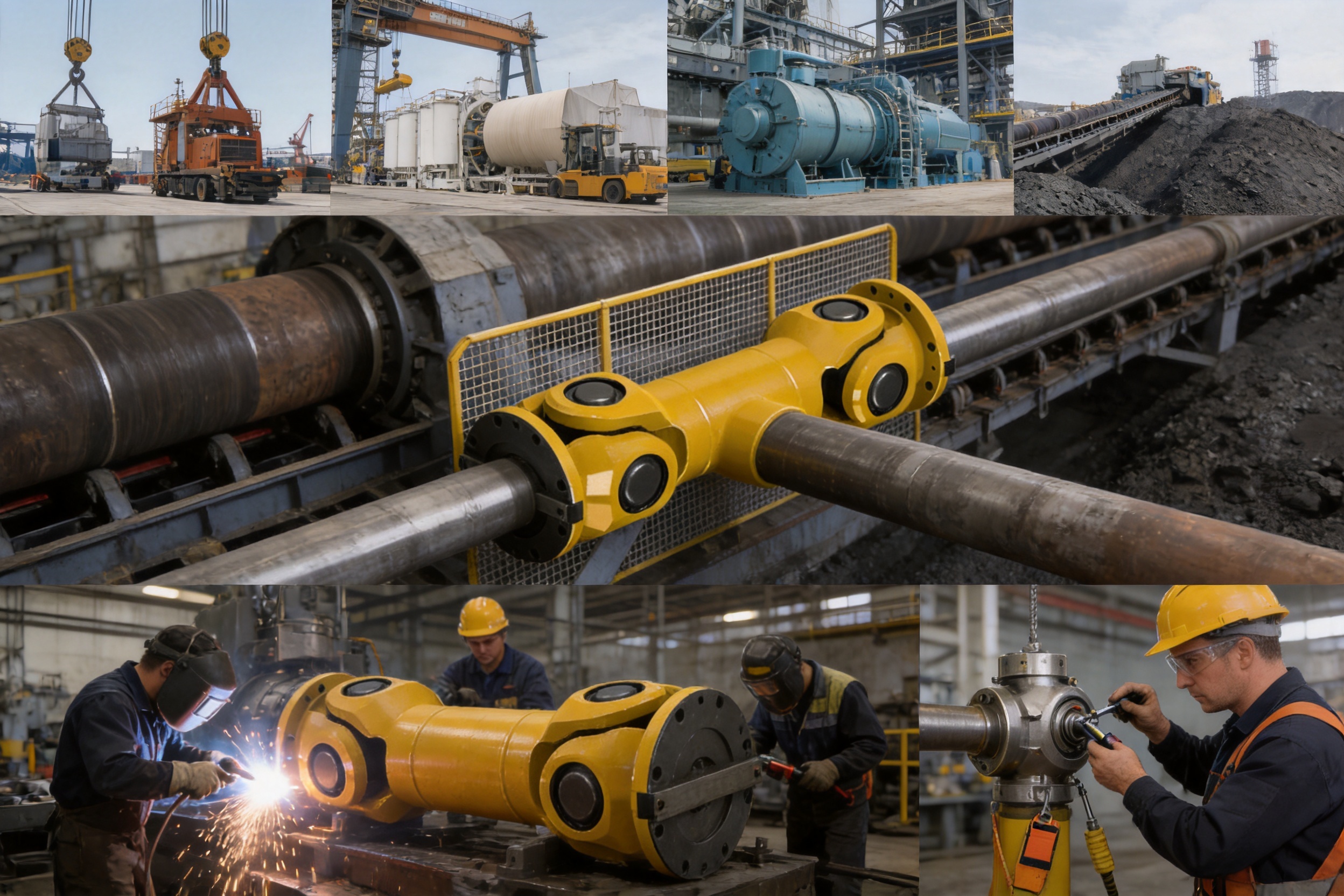
The company maintains an ISO 9001-related quality-management framework and supplies products for metallurgical equipment, mining equipment, water equipment, lifting equipment, paper equipment, port equipment, and other industrial fields. This application experience helps connect product design with real operating conditions.
13. Practical Comparison of Product Benefits
| Requirement | SWC-WH Design Response | Practical Benefit |
| Angular shaft misalignment | Universal-joint articulation | Allows torque transmission between shafts operating at a controlled angle |
| High torque | Metallic non-elastic load path | Suitable for demanding industrial transmission duties |
| Axial displacement not required | Non-expansion construction | Provides a direct and stable axial arrangement |
| Simple structural requirement | Welded body | Reduces structural complexity and can simplify assembly |
| Wide application range | Fourteen listed sizes | Supports selection from 2.5 to 1,000 kN·m nominal torque |
| Heavy industrial environment | Robust metallic construction | Appropriate for metallurgy, mining, lifting, port, and material-handling equipment |
| Special shaft interface | Customization capability | Allows adaptation to non-standard machine connections |
The principal competitive advantage of the SWC-WH is the combination of high torque capacity and substantial angular flexibility in a welded, non-expansion structure. Many alternative couplings provide one or two of these characteristics but not necessarily all of them in the same product family.
For example, a rigid coupling may be strong but alignment-sensitive. An elastomeric coupling may damp vibration but have limited torque density or a finite insert life. A gear coupling may provide high torque but require more intensive lubrication and tooth maintenance. A disc coupling may offer precision performance but may not be ideal for large angular movement. The SWC-WH provides a specialized solution for applications in which the universal-joint principle is the best match.
14. Limitations and Selection Boundaries
Responsible product selection requires understanding the boundaries of the design. The SWC-WH should not be selected when substantial axial expansion must be absorbed by the coupling. In that case, an expansion type or another axial-compensating coupling should be evaluated.
The coupling should also not be used to compensate for uncontrolled parallel offset, excessive installation error, or a structural defect in the machinery. Angular flexibility does not eliminate the need for proper machine alignment and adequate shaft support.
High-speed service requires particular attention to balance, bearing life, critical speed, and joint kinematics. The catalog torque rating alone does not establish suitability at every rotational speed. A complete review should be performed for high-speed or highly dynamic applications.
Severe torsional vibration may require a torsional analysis. Because the SWC-WH uses a non-elastic transmission path, it may not provide the damping expected from an elastomeric coupling. If the system contains a large motor, variable-frequency drive, reciprocating load, or frequent torque reversals, the drivetrain should be assessed for resonance and fatigue.
Finally, the stated model data should be confirmed against the latest approved drawing and quotation before manufacture. Dimensions, materials, tolerances, lubrication arrangements, and allowable operating conditions can vary according to project requirements and customization.
15. Recommended Procurement Process
A reliable procurement process begins with application definition. The customer should describe the machine, the drive motor, the driven load, operating hours, shaft angle, speed range, torque conditions, and environmental factors.
The next step is preliminary model selection using nominal torque, fatigue torque, rotation diameter, angle, and installation dimensions. The manufacturer can then verify the selection against detailed shaft and flange drawings.
After technical confirmation, the order should define the required inspection documents, coating, balancing, packaging, spare parts, installation instructions, and warranty conditions. For critical equipment, a drawing approval stage should be included before production.
During manufacturing, quality documents should be maintained for traceability. Before shipment, the coupling should be checked for dimensions, assembly condition, surface protection, identification marking, and packaging integrity. Heavy components should be packaged and lifted according to their mass and center of gravity.
At the installation stage, the purchaser should verify the shaft condition, alignment, fastener installation, lubrication, guard clearance, and rotation direction. Commissioning should begin at low speed where possible, followed by monitoring of vibration, temperature, noise, and fastener condition.
16. Frequently Asked Questions
What is the SWC-WH coupling used for?
The SWC-WH is used to transmit torque between two shafts that operate with a controlled angular misalignment. It is intended for industrial equipment that requires angular flexibility but does not require the coupling to compensate for axial displacement or thermal expansion.
What does “non-expansion” mean?
Non-expansion means that the coupling is not designed to provide axial movement between the connected shafts. The axial relationship is maintained by the coupling and machine arrangement. Any thermal or structural axial movement must be handled elsewhere in the system or evaluated through an alternative coupling design.
Is the SWC-WH an elastic coupling?
No. It is a flexible coupling with non-elastic elements. Its flexibility is produced by the mechanical articulation of a universal-joint structure rather than by a rubber, polyurethane, or other elastomeric insert.
What is the available torque range?
The listed series covers nominal torque from 2.5 kN·m for SWC100WH to 1,000 kN·m for SWC550WH. Fatigue torque values range from 1.25 kN·m to 500 kN·m across the listed models.
What is the maximum shaft angle?
The SWC100WH, SWC120WH, and SWC150WH models are listed for an axis angle of up to 25 degrees. Models SWC180WH through SWC550WH are listed for an axis angle of up to 15 degrees. The permitted value should be confirmed for the actual operating conditions and selected configuration.
Can it replace a rigid coupling?
It can be considered as an alternative where angular misalignment exists and a rigid coupling would impose excessive alignment demands. It is not necessarily the best choice for a short, precisely aligned shaft connection where no flexibility is needed.
Can it replace an elastomeric coupling?
It may be appropriate when high torque, metallic durability, and angular flexibility are more important than torsional damping. If the system requires significant vibration absorption, electrical insulation, or axial flexibility, an elastomeric or another specialized coupling may be more suitable.
Does the coupling require maintenance?
Yes. The coupling should be inspected for wear, looseness, vibration, abnormal noise, temperature rise, corrosion, and lubrication condition. The maintenance interval depends on speed, load, operating angle, environment, and duty cycle.
Can the coupling be customized?
Yes. Non-standard coupling design and manufacture are available. Customization may include length, bore, shaft interface, bolt pattern, materials, coating, balancing, or other project-specific requirements, subject to engineering review.
What information is needed for a quotation?
Important information includes motor power, rotational speed, normal and peak torque, operating angle, shaft dimensions, keyways, flange drawings, shaft-end distance, environmental conditions, operating temperature, duty cycle, and whether axial expansion is present.
Where is the product manufactured?
The product is manufactured by Zhongye Heavy Industry Technology (Zhenjiang) Co., Ltd. in Zhenjiang, Jiangsu Province, China. The company integrates product development, manufacturing, sales, technical support, and after-sales service.
What industries can use the product?
Potential industries include metallurgy, mining, material handling, lifting, ports, paper production, water equipment, food processing, and other industrial machinery sectors requiring high-torque angular transmission.
17. Conclusion
The SWC-WH type non-expansion welded universal coupling is a practical solution for industrial drive systems that require robust torque transmission and angular shaft flexibility without axial expansion compensation. Its welded construction supports structural simplicity, while the universal-joint configuration permits the connection of shafts operating at a controlled angle.
The series offers a broad range of sizes, from 100 mm to 550 mm rotation diameter and from 2.5 kN·m to 1,000 kN·m nominal torque. The smaller models provide an axis-angle capability of up to 25 degrees, while the larger models provide up to 15 degrees. This range allows the product to serve both compact machinery and large heavy-duty equipment.
Compared with rigid couplings, the SWC-WH reduces sensitivity to angular misalignment. Compared with many elastomeric designs, it provides a metallic load path without relying on an elastic insert. Compared with other high-torque coupling types, its universal-joint arrangement can offer a strong combination of angular movement, torque density, and industrial durability.
The product should be selected through a complete engineering review that includes torque, speed, fatigue, shaft angle, axial movement, environment, installation space, guarding, and maintenance access. When these factors are correctly evaluated, the SWC-WH can provide stable and efficient power transmission in demanding industrial systems.
The manufacturer's integrated research, manufacturing, testing, customization, and service capabilities further support the product. Its heavy and precision workshops, quality-management approach, broad coupling experience, and non-standard design capability make it suitable for customers seeking both standard products and engineered transmission solutions.
References
1. SWC-WH Type Non-Expansion Welded Universal Coupling Product Specification, manufacturer-provided technical data.
2. Manufacturer's Basic Parameters and Main Dimensions Table for WH Type Non-Expansion Welded Universal Coupling.
3. Manufacturer's Corporate Information and Industrial Coupling Product Catalogue.
4. ISO 9001, Quality Management Systems — Requirements.
5. General Principles of Industrial Shaft Alignment and Coupling Installation Practice.
6. General Guidelines for Mechanical Power Transmission Coupling Selection, Torque Rating, Fatigue Assessment, and Maintenance.
7. General Engineering Practice for Welding Quality Control, Dimensional Inspection, Rotating Equipment Safety, and Protective Guarding.
Product: SWC-WH type non-expansion welded universal coupling

- Quick Links
- About
- Products
- Our Service
- News & Events
- Contact
- Products Series
- Flexible Couplings with Non-Elastic Elements
- Flexible Couplings with Metal Elastic Elements
- Flexible Couplings with Non-Metallic Elastic Elements
- Safety Coupling
- Rigid Coupling
- Contact Us
- Tel : +86 511 8572 3800 +86 511 8572 3900
- Mobile : +86 15106109009
- Email : sales@couplingzy.com
- Add:No.1 Zhongye Yingbin Avenue, Gaozi Street, Dantu Economic Development Zone, Zhenjiang City, Jiangsu Province, China.


