:+86 15106109009
:sales@couplingzy.com


 English
  русский
  Español
  عربى
عربى  Português
  Deutsch
  Türk
Türk  Indonesia

MCL-I Plus-Shaped Elastic Coupling for Integrated Torque Transmission and Braking
Content
- 1 1. Product Overview and Operating Principle
- 2 2. Main Technical Characteristics
- 3 3. Technical Specification Range
- 4 4. Advantages Compared with Conventional Coupling Solutions
- 5 5. Elastic Element Materials and Service Behavior
- 6 6. Application Areas
- 7 7. Manufacturing Process and Engineering Strengths
- 8 8. Installation Recommendations
- 9 9. Maintenance and Failure Prevention
- 10 10. Coupling Selection Method
- 11 11. Customization and Non-Standard Engineering
- 12 12. Company Manufacturing and Service Advantages
- 13 13. Safety Considerations
- 14 14. Frequently Asked Questions
- 14.1 Q1: What is the main function of the MCL-I coupling?
- 14.2 Q2: Why is it described as a plus-shaped or plum-shaped coupling?
- 14.3 Q3: What materials are used for the elastic element?
- 14.4 Q4: Does the coupling include a complete brake?
- 14.5 Q5: What is the available torque range?
- 14.6 Q6: What is the highest listed allowable speed?
- 14.7 Q7: Can the MCL-I compensate for poor shaft alignment?
- 14.8 Q8: Is the elastic element replaceable?
- 14.9 Q9: Is the product suitable for lifting machinery?
- 14.10 Q10: Can special bore sizes or dimensions be supplied?
- 14.11 Q11: How should the correct model be selected?
- 14.12 Q12: What information should be supplied for a quotation?
- 15 15. Conclusion
- 16 References
- 17 Product: MCL-I type plus-shaped elastic coupling(Q/YM 35015X-2018)
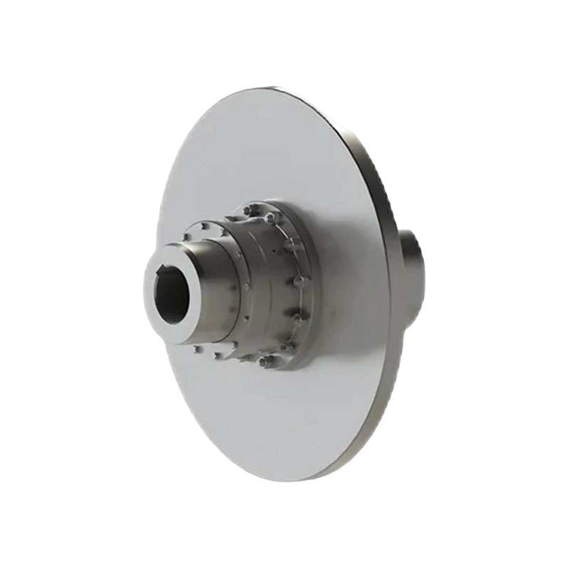
The MCL-I plus-shaped elastic coupling is a precision power-transmission component designed for industrial machinery that requires dependable torque transfer, vibration absorption, shaft misalignment compensation, and controlled braking. Manufactured in accordance with Q/YM 35015X-2018 and GB/T 5272-2002, this coupling combines the operating principles of a claw-type elastic coupling with an integrated split brake wheel. It is therefore suitable for systems in which a conventional flexible coupling and a separate braking arrangement would otherwise occupy more space and require additional installation interfaces.
The product belongs to the category of flexible couplings with non-metallic elastic elements. Its elastic element is generally produced from polyurethane or cast nylon, while the hubs, claw half couplings, and brake wheel components are manufactured as engineered metallic parts. During operation, torque passes from one shaft to the other through radial compression between the claws of the half couplings and the lobes of the plum-shaped elastic element. This arrangement permits torque transmission while reducing the direct transfer of shock loads, torsional vibration, and moderate installation errors.
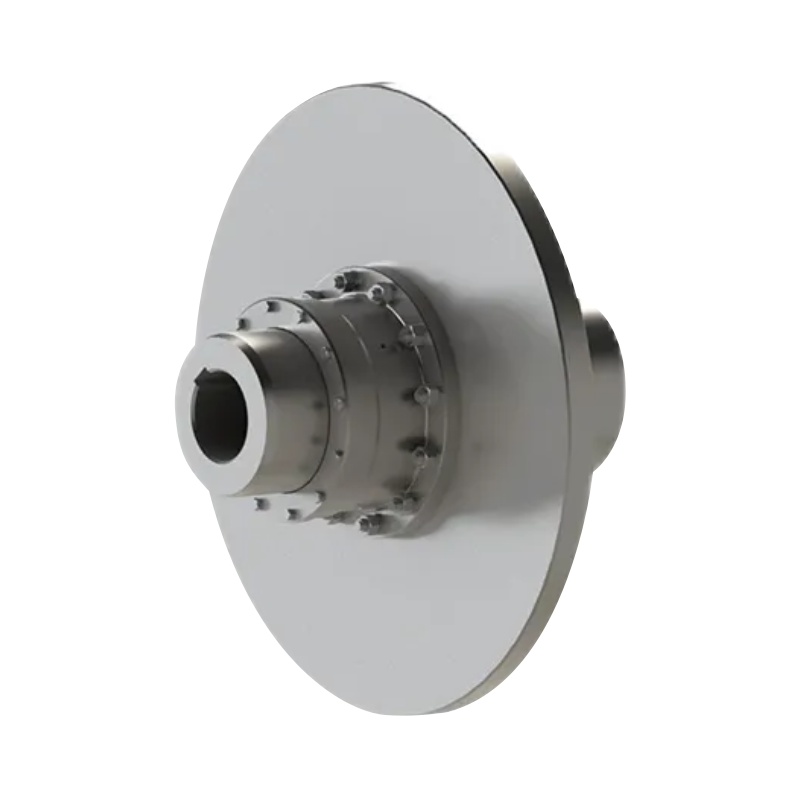
The defining feature of the MCL-I series is its LMZ-I split brake wheel. The brake wheel is installed as part of the coupling structure and works with an external braking device. When the external brake is activated, the brake wheel supports rapid stopping, holding, or positioning of the driven equipment. This integrated transmission-and-braking concept makes the coupling particularly valuable in lifting equipment, metallurgical machinery, mining systems, port machinery, and other heavy industrial applications where stopping performance and operational safety are essential.
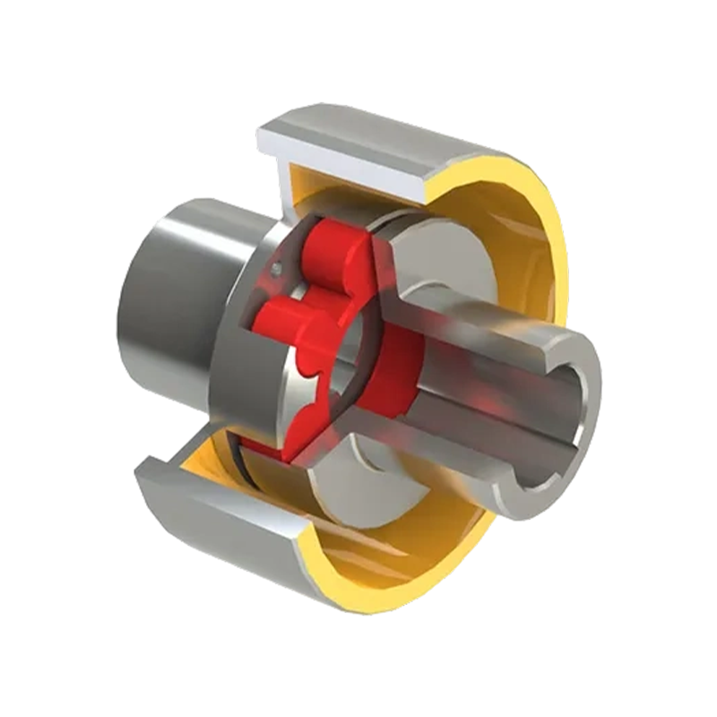
MCL-I type plus-shaped elastic coupling(Q/YM 35015X-2018)
1. Product Overview and Operating Principle
A flexible coupling is installed between two shafts to transmit rotary power while accommodating a certain degree of angular, parallel, and axial displacement. In practical machinery, perfect shaft alignment is difficult to maintain because of foundation settlement, thermal expansion, bearing tolerances, assembly error, and deformation under load. A rigid connection may transmit these errors directly into the bearings and connected equipment. The MCL-I coupling uses a non-metallic elastic element to introduce controlled flexibility into the drive line.
The coupling normally consists of two claw half couplings, a central plum-shaped elastic element, and a split brake wheel. Each half coupling is connected to one shaft through a specified bore and key arrangement. The claws of the two half couplings face one another, with the elastic element positioned between them. The lobes of the elastic element enter the spaces between the claws. When one shaft rotates, the claws compress the elastic lobes and transfer the driving force to the opposite half coupling.
Unlike a fully rigid coupling, the MCL-I does not rely on direct metal-to-metal contact for every point of torque transmission. The elastic element forms a resilient interface. It can absorb a portion of torque fluctuation and impact energy, helping to protect motors, gearboxes, drums, rolls, pumps, and other connected machinery from sudden load changes.
The split brake wheel adds a second functional layer. It is designed to cooperate with an external brake, such as a drum brake or another compatible braking assembly. Because the brake wheel is integrated into the coupling configuration, the braking force can be applied close to the shaft connection. This can simplify the layout of the drive system and support more direct control of stopping and holding operations.
The product name is sometimes translated as a plus-shaped, quincunx, or plum-blossom elastic coupling. These terms refer to the geometry of the non-metallic elastic element and the arrangement of its lobes. In technical selection, the complete model designation, nominal torque, bore range, speed, dimensions, and elastic element type should be used rather than relying only on a translated product name.
2. Main Technical Characteristics
2.1 Wide torque range
The MCL-I product range covers nominal torque ratings from 355 N·m to 14,000 N·m. This allows the series to serve both medium-duty industrial drives and large, heavily loaded transmission systems. The available sizes include compact models such as MCL5-I-160 and larger models such as MCL14-I-80.
A broad torque range is important because coupling selection must consider more than the motor’s rated power. Starting torque, braking torque, acceleration, reversing, impact loading, duty cycle, and the characteristics of the driven machine can all increase the actual coupling load. A properly selected MCL-I model can provide a suitable margin between working torque and nominal torque capacity.
2.2 Integrated braking function
The LMZ-I split brake wheel is the principal difference between the MCL-I and a standard non-braking claw coupling. It allows the coupling to participate in the braking layout without requiring a separate shaft-mounted brake wheel in another position. This can reduce the number of shaft extensions and simplify the arrangement of the drive train.
Integrated braking is particularly useful where the driven machine must stop quickly, remain stationary during loading, or position accurately at a designated point. Examples include lifting mechanisms, conveyor systems with controlled stopping, metallurgical handling equipment, and port machinery. The exact braking performance depends on the external brake, brake lining, brake force, rotating inertia, operating speed, and control system. The coupling should therefore be treated as a mechanical interface for braking rather than as a complete brake system by itself.
2.3 Elastic shock absorption
Polyurethane or cast nylon elastic elements provide a resilient connection between the two metal hubs. Under transient loads, the element deforms slightly and helps reduce the peak impact transmitted through the shaft line. This is useful for equipment with frequent starts and stops, intermittent loading, reversing cycles, or fluctuating resistance.
By moderating torsional shock, the coupling can contribute to lower mechanical stress in gears, shafts, keys, and bearings. It can also help reduce noise generated by sudden torque changes. The actual damping characteristics depend on the selected elastic element material, hardness, operating temperature, load frequency, and environmental conditions.
2.4 Displacement compensation
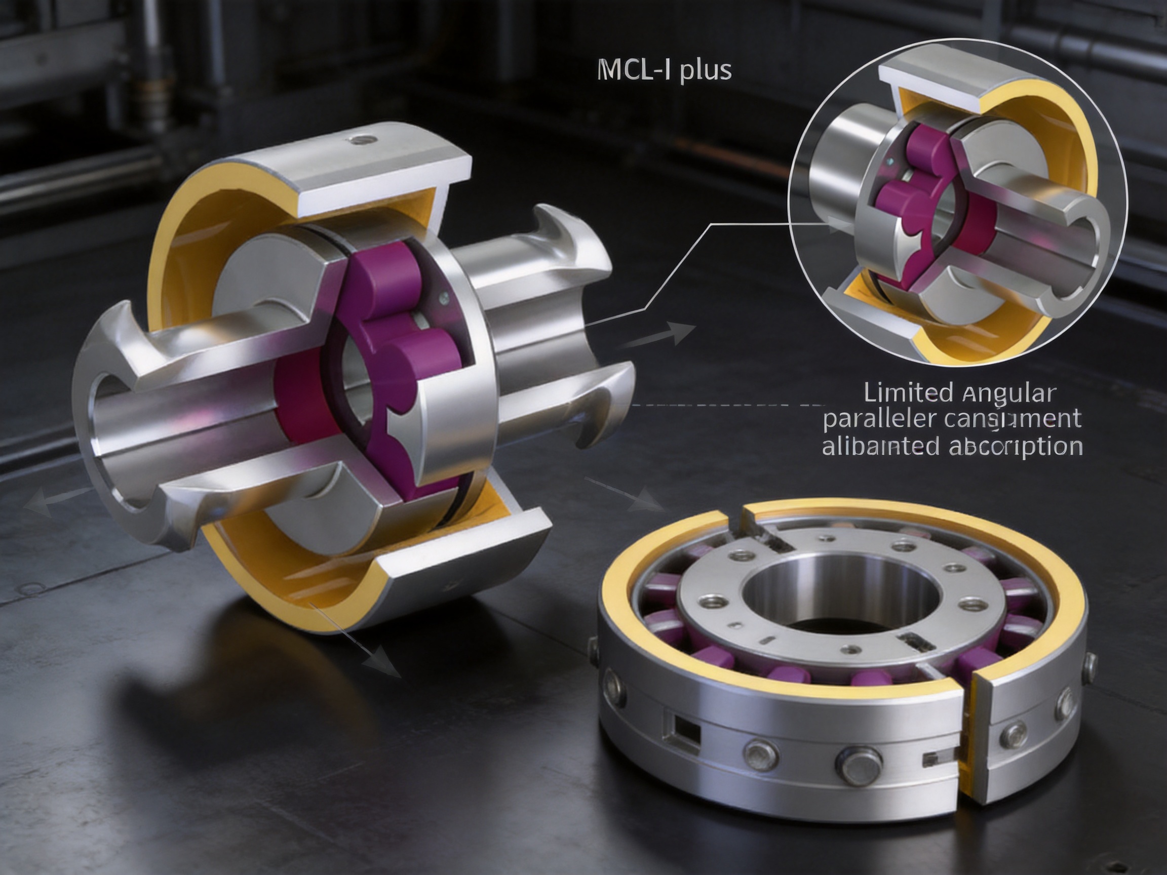
The MCL-I design can accommodate limited angular, radial, and axial displacement between the connected shafts. This compensation capability helps prevent excessive reaction forces caused by small alignment deviations. It does not eliminate the need for accurate installation. Good alignment remains necessary to control wear, reduce vibration, and maximize service life.
Because the elastic element is replaceable, the coupling can continue to provide compensation without requiring the complete replacement of the metal hubs. This is a practical advantage for equipment installed in locations where maintenance time is costly.
2.5 Split construction and maintenance convenience
The split structure is designed to make inspection and replacement more convenient than a fully enclosed or permanently assembled arrangement. When the elastic element reaches the end of its service life, maintenance personnel can normally inspect the element and replace it without changing the complete coupling assembly. The exact procedure depends on the shaft arrangement, guard design, brake installation, and available maintenance clearance.
Convenient replacement is especially valuable in heavy industrial applications. A flexible coupling may be installed in a high-duty drive that operates continuously or in a location where dismantling a motor, gearbox, or drum is difficult. A replaceable elastic element can reduce outage duration and help control maintenance costs.
3. Technical Specification Range
The following table summarizes the available MCL-I configurations and the principal data supplied for the product range. Dimensions and bore combinations should be confirmed against the latest technical drawing before ordering, especially where a project requires a specific brake arrangement, keyway, shaft extension, or installation clearance.
| Type | Nominal Torque Tn (N·m) | Allowable Speed (r/min) | Shaft Hole Diameter or Bore Range (mm) | L (mm) | L0 (mm) | D0 (mm) | B (mm) | D (mm) | Elastic Element | Mass (kg) | Moment of Inertia (kg·m²) |
|---|---|---|---|---|---|---|---|---|---|---|---|
| MCL5-I-160 | 355 | 4750 | 25, 28, 30, 32, 35, 38, 40, 42, 45 | 50 | 127 | 160 | 70 | 105 | MT5 | 6.602 | 0.019 |
| MCL5-I-200 | 380 | Not stated in supplied data | 25, 28, 30, 32, 35, 38, 40, 42, 45 | 85 | 200 | Not stated | Not stated | Not stated | MT5 | 9.204 | 0.044 |
| MCL6-I-200 | 450 | Not stated in supplied data | 30, 32, 35, 38, 40, 42, 45, 48 | 55 | 143 | 200 | Not stated | 125 | MT6 | 11.45 | 0.052 |
| MCL7-I-200 | 710 | Not stated in supplied data | 35*, 38*, 40*, 42*, 45, 48, 50, 55, 56 | 60 | 159 | 200 | Not stated | 145 | MT7 | 13.96 | 0.064 |
| MCL7-I-250 | 3050 | Not stated in supplied data | 35*, 38*, 40*, 42*, 45, 48, 50, 55, 56 | 105 | 250 | Not stated | Not stated | Not stated | MT7 | 20.09 | 0.144 |
| MCL8-I-250 | 1250 | Not stated in supplied data | 45*, 48*, 50, 55, 56, 60, 63, 65 | 70 | 181 | 250 | Not stated | 168 | MT8 | 24.65 | 0.175 |
| MCL8-I-315 | 2400 | Not stated in supplied data | 45*, 48*, 50, 55, 56, 60, 63, 65 | 135 | 315 | Not stated | Not stated | Not stated | MT8 | 34.13 | 0.374 |
| MCL9-I-315 | 2000 | Not stated in supplied data | 50*, 55*, 56*, 60, 63, 65, 70, 71, 75, 80 | 80 | 208 | 315 | Not stated | 198 | MT9 | 41.67 | 0.45 |
| MCL9-I-400 | 1900 | Not stated in supplied data | 50, 55*, 56*, 60, 63, 65, 70, 71, 75, 80 | 170 | 400 | Not stated | Not stated | Not stated | MT9 | 65.61 | 1.259 |
| MCL10-I-40 | 3150 | Not stated in supplied data | 60*, 63*, 65*, 70, 71, 75, 80, 85, 90, 95, 100 | 90 | 230 | 400 | Not stated | 228 | MT10 | 74.53 | 1.4 |
| MCL10-I-50 | 1500 | Not stated in supplied data | 60*, 63*, 65*, 70, 71, 75, 80, 85, 90, 95, 100 | 210 | 500 | Not stated | Not stated | Not stated | MT10 | 110.6 | 3.472 |
| MCL11-I-50 | 5000 | Not stated in supplied data | 70*, 71*, 75*, 80*, 85, 90, 95, 100, 110, 120 | 100 | 260 | 500 | Not stated | 258 | MT11 | 121.7 | 3.715 |
| MCL12-I-63 | 7100 | 1200 | 80*, 85*, 90*, 95*, 100, 110, 120, 125, 130 | 115 | 297 | 630 | 265 | 298 | MT12 | 213.7 | 10.24 |
| MCL13-I-71 | 12500 | 1050 | 90*, 95*, 100*, 110*, 120*, 125, 130, 140, 150 | 125 | 323 | 710 | 300 | 358 | MT13 | 341.6 | 19.99 |
| MCL14-I-80 | 14000 | 950 | 100*, 110*, 120*, 125*, 130*, 140*, 150, 160 | 135 | 333 | 800 | 340 | 400 | MT14 | 510.1 | 39.36 |
An asterisk in the bore information is retained from the supplied technical data. It may indicate a particular machining or configuration note and should be checked with the manufacturer during technical confirmation. Several intermediate entries in the supplied table do not include every dimensional or speed field. For this reason, the selection process should use the complete drawing and order confirmation rather than treating omitted fields as zero or as universal values.
4. Advantages Compared with Conventional Coupling Solutions
4.1 Compared with rigid couplings
Rigid couplings provide a direct connection and are useful when the shafts are accurately aligned and the system requires no meaningful flexibility. However, they transfer alignment errors and shock loads directly through the shaft train. In large industrial machines, even small deviations can increase bearing loads, vibration, and maintenance requirements.
The MCL-I offers a more forgiving connection. Its non-metallic element provides limited displacement compensation and absorbs part of the torsional impact. This makes it better suited to machinery that experiences foundation movement, thermal variation, intermittent loads, or frequent starts and stops. The trade-off is that the elastic element is a service component and must be inspected and replaced when worn.
4.2 Compared with ordinary claw or jaw couplings
A standard claw coupling and the MCL-I share the basic principle of using a flexible lobed element between two hubs. The MCL-I, however, is configured with an integrated split brake wheel. This gives the product a distinct advantage in drive systems that need both flexible torque transmission and mechanical braking.
Using a separate brake wheel may require additional shaft length, a separate support arrangement, more alignment work, and extra guarding. The integrated design can create a more compact transmission layout and may reduce the number of interfaces that must be coordinated during installation. It also places the brake function within the same mechanical assembly as the coupling, which can simplify equipment design.
4.3 Compared with metal elastic couplings
Metal elastic couplings, including diaphragm, grid, and serpentine spring designs, can provide excellent performance in specific high-speed or high-precision applications. They may also tolerate particular environmental conditions that are unsuitable for polymeric elements. Nevertheless, metal designs can require more involved inspection, precise assembly, or more complicated replacement procedures.
The MCL-I uses a non-metallic elastic element that is comparatively simple to inspect and replace. Its construction is well suited to applications where shock absorption, economical maintenance, and practical field service are more important than extremely high torsional stiffness. The choice between a non-metallic and metal elastic coupling should always consider speed, temperature, chemical exposure, torsional stiffness, maintenance practice, and braking requirements.
4.4 Compared with separate coupling and brake assemblies
Combining the coupling and brake wheel into one product can reduce equipment footprint. A separate arrangement may need a coupling, a brake disc or wheel, additional hubs, support bearings, and a longer shaft. Each added component introduces another possible source of alignment error, fastener loosening, or maintenance demand.
The MCL-I does not remove the need for proper brake selection or safety design, but it can make the mechanical architecture more coordinated. For lifting and positioning machinery, this coordination can be especially useful because torque transmission and stopping behavior are closely related.
5. Elastic Element Materials and Service Behavior
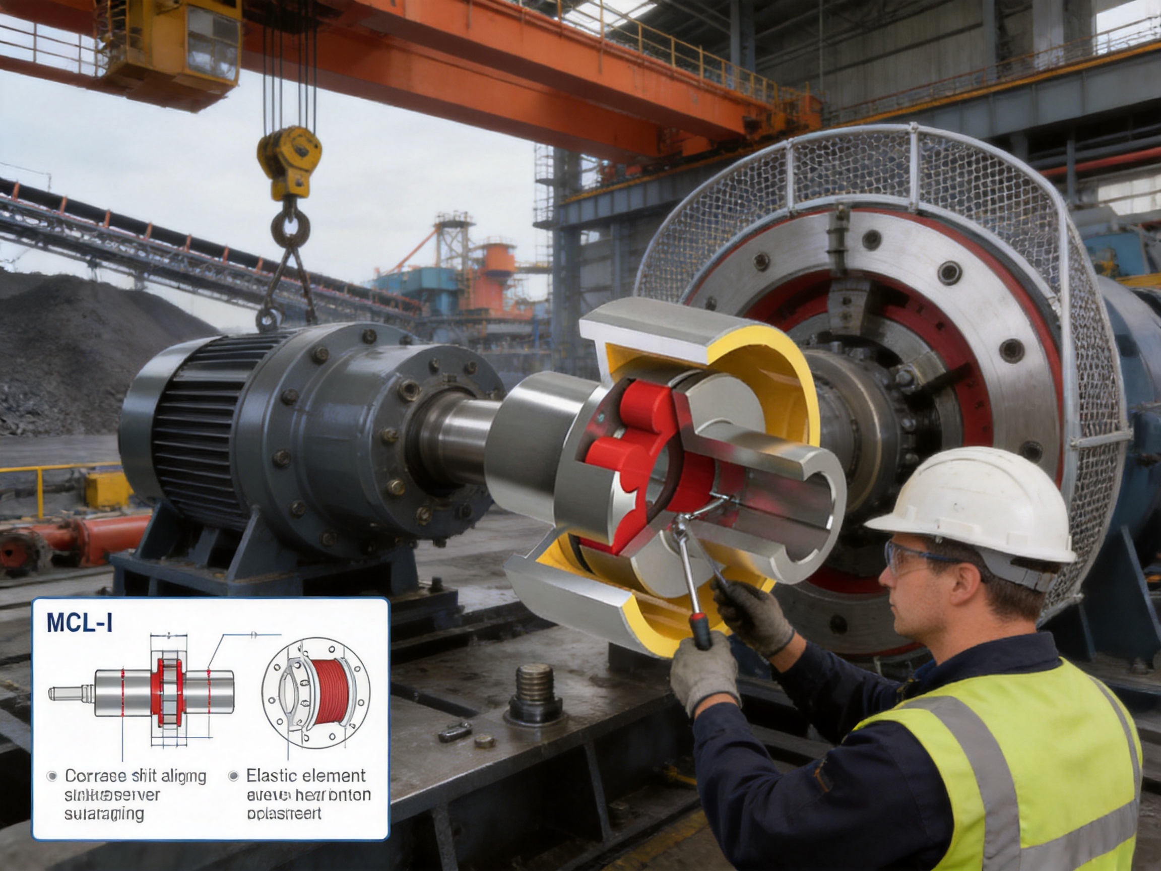
The central elastic element may be manufactured from polyurethane or cast nylon, depending on the model and application requirements. These materials have different mechanical characteristics, and the correct choice should be confirmed with the technical department before production.
5.1 Polyurethane elements
Polyurethane is widely used where resilient deformation, vibration reduction, and impact absorption are important. It can provide a useful balance of flexibility and load-carrying capability. Its behavior is affected by temperature, oil exposure, aging, ultraviolet radiation, and the frequency of cyclic loading.
In a drive with frequent starts and stops, the polyurethane element may reduce the severity of torque peaks. It can also help reduce the transmission of high-frequency vibration between the motor and driven machine. The element should be protected from excessive heat and incompatible chemicals, and it should be inspected for cracking, hardening, permanent deformation, or lobe wear.
5.2 Cast nylon elements
Cast nylon can provide high mechanical strength and good resistance to wear in suitable operating conditions. It may be selected when the application requires a firmer elastic connection or a particular combination of load capacity and dimensional stability. As with polyurethane, operating temperature, moisture, lubrication contamination, and chemical exposure must be considered.
Material selection should not be based solely on nominal torque. The elastic element must withstand the actual duty cycle, including acceleration, braking, reversing, overload events, and the number of operating cycles. A coupling that is satisfactory for a smooth motor-driven pump may require a different element selection when installed in a reversing hoist or impact-loaded conveyor.
6. Application Areas
6.1 Metallurgical equipment
Metallurgical production lines frequently involve high loads, elevated temperatures, repeated starts and stops, and demanding operating environments. Rolling mills, transfer mechanisms, shears, coilers, and material-handling systems may require both shock absorption and controlled stopping. The MCL-I can be considered for suitable shaft lines where its speed, torque, temperature, and brake compatibility meet the engineering requirements.
6.2 Lifting and transportation machinery
Lifting equipment must manage acceleration, deceleration, suspended loads, positioning, and holding. A flexible coupling with a brake wheel can support the integration of the drive and braking systems. It can also help moderate the torsional effects generated during hoisting and lowering cycles.
Safety-critical lifting applications require a complete system assessment. The coupling, brake, motor, gearbox, drum, shaft, keys, fasteners, controls, emergency stop circuit, and overload protection must be evaluated together. The MCL-I is a mechanical component within that system and should not be used as a substitute for a certified lifting safety arrangement.
6.3 Mining machinery
Mining equipment operates under dust, vibration, shock, variable loads, and difficult maintenance conditions. Crushers, conveyors, feeders, winches, and auxiliary drives can benefit from a coupling that provides a replaceable elastic element and a robust metallic structure. The integrated brake wheel may be useful in drives that require controlled stopping or holding.
Mining installations should include effective guards and contamination control. Dust accumulation around the brake wheel or coupling can influence heat dissipation and inspection access. Maintenance personnel should establish a regular schedule for checking fasteners, bore connections, elastic element condition, shaft alignment, and brake operation.
6.4 Port and cargo-handling equipment
Port machinery often combines high inertia with repetitive positioning cycles. Cranes, hoists, winches, conveyors, and transfer systems must stop reliably while handling changing loads and operating in exposed environments. The MCL-I can provide a compact connection for applications where torque transfer and mechanical braking are required in one shaft assembly.
6.5 Water, paper, and general industrial equipment
The product range can also be evaluated for water equipment, paper machinery, general lifting equipment, and other industrial systems. The final choice depends on the operating speed, transmitted torque, shaft diameter, available installation space, environmental conditions, and the required braking arrangement.
7. Manufacturing Process and Engineering Strengths
The quality of a coupling is determined not only by its basic design but also by the consistency of its manufacturing process. A heavy-duty coupling must maintain accurate bore dimensions, concentricity, face relationships, claw geometry, surface quality, and balance. The manufacturing organization behind the MCL-I series integrates research and development, production, testing, and sales support so that design requirements can be carried through to the finished component.
7.1 Product design and application engineering
Engineering begins with the operating conditions of the customer’s equipment. Important inputs include motor power, speed, starting method, driven-machine torque, braking torque, shaft diameters, shaft spacing, keyway dimensions, installation position, ambient temperature, and maintenance restrictions.
The design process must also consider the interaction between the coupling and the brake. The brake wheel must have suitable dimensions and mechanical integrity for the external brake assembly. Clearance, guarding, heat generation, and access for inspection are all important. This application-focused approach helps prevent the common mistake of selecting a coupling only by nominal motor power.
7.2 Heavy and precision workshop capability
The company’s new workshop covers approximately 16,463.52 square meters. It includes a heavy workshop of about 5,500 square meters, a precision workshop of about 4,600 square meters, an office building and gymnasium, a dining hall, a warehouse, and supporting roads, green areas, and parking facilities.
The separation of heavy and precision production areas supports different manufacturing requirements. Large coupling components can be handled and machined in an area suited to heavy work, while dimensional finishing, inspection, and precision operations can be organized in a controlled workshop environment. This facility arrangement is valuable for a product family that ranges from compact couplings to models with a nominal torque rating of 14,000 N·m.
7.3 Machining and dimensional control
Coupling hubs and brake wheels require accurate turning, boring, drilling, keyway processing, and face machining. Concentricity between the bore and outside diameter is important because eccentricity can create vibration at operating speed. The relationship between the hub faces and shaft centerline also affects installation and alignment.
Precision machining processes should be supported by inspection of critical dimensions. Depending on the configuration, this may include bore measurement, outside-diameter measurement, face runout, radial runout, keyway verification, bolt-hole positioning, and visual inspection of machined surfaces. Consistent process control reduces variation between production batches and helps ensure that replacement parts fit the original installation.
7.4 Elastic element production and inspection
The non-metallic elastic element is a functional part rather than a simple spacer. Its lobe geometry, hardness, dimensional accuracy, and material condition influence torque transmission, damping, and service life. Material preparation, molding or casting, curing, trimming, and final inspection must be controlled carefully.
Inspection may include dimensional checks, appearance checks, hardness verification, and confirmation that there are no cracks, voids, excessive flash, or deformation. The element should be stored in conditions that limit contamination, extreme temperatures, and unnecessary aging before installation.
7.5 Assembly and quality assurance
Assembly quality influences the service behavior of the complete coupling. The elastic element must be seated correctly between the claws, and the split brake wheel must be installed with the required fastener torque and alignment. Contact surfaces should be clean, shaft fits should match the specified tolerances, and keys and locking components should be correctly fitted.
A quality assurance system based on documented procedures helps control material traceability, process inspection, final verification, and release of finished products. The company states that its products comply with international standards and certifications such as ISO 9001. Customers should request the applicable quality documents and inspection records for projects that require formal documentation.
7.6 Testing capability
Testing facilities support the verification of product quality and performance. For a coupling of this type, relevant checks may include dimensional inspection, rotational balance assessment where applicable, material verification, elastic element checks, and functional confirmation of the brake wheel assembly. For customized or especially demanding applications, additional testing and engineering review may be arranged according to the project specification.
Testing should be matched to the risk and duty of the application. A low-speed auxiliary drive and a high-inertia lifting drive do not present identical requirements. The company’s ability to provide technical support and non-standard design solutions allows the product to be adapted more effectively to different industrial conditions.
8. Installation Recommendations
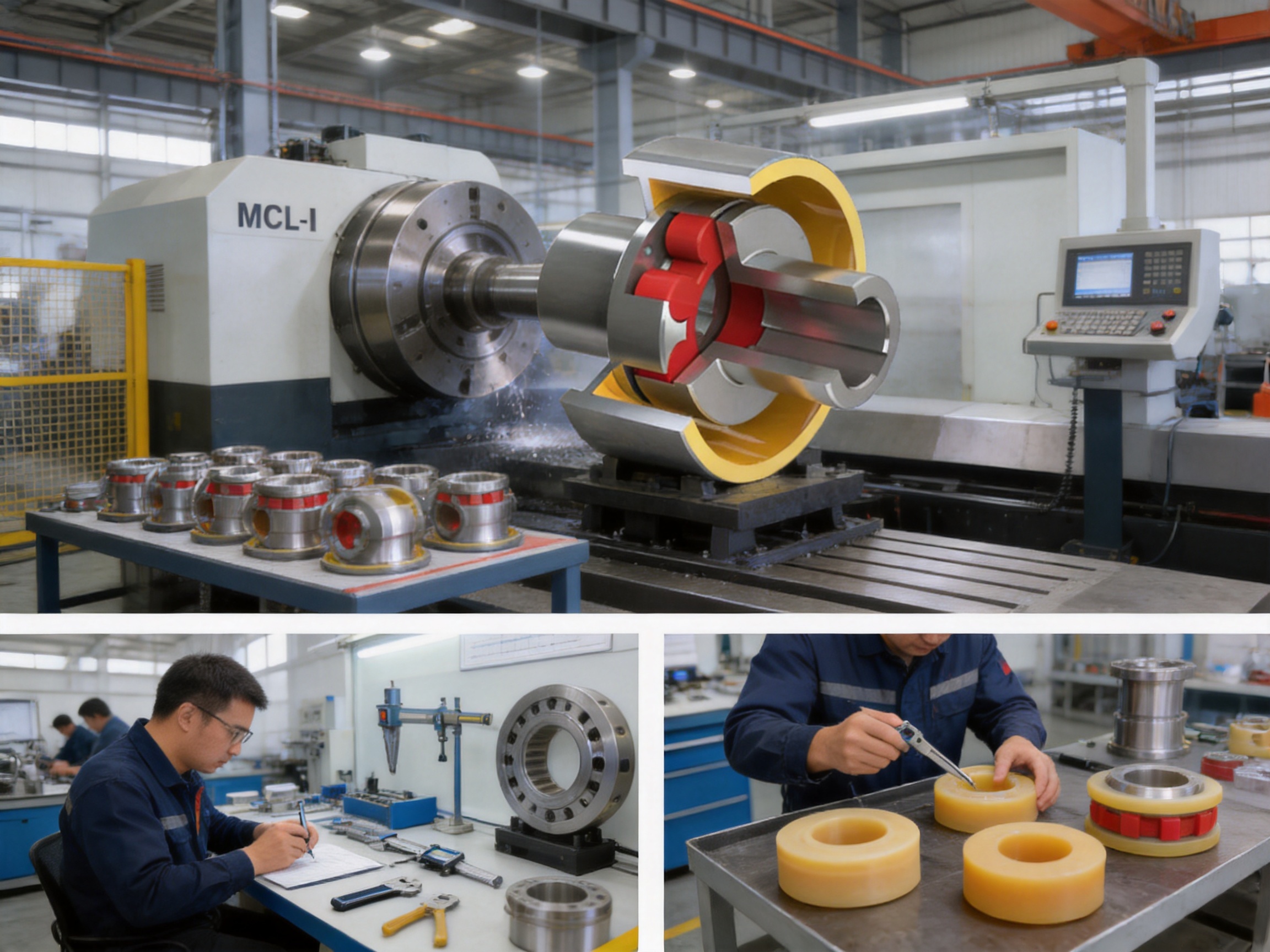
Before installation, verify the model, bore diameters, keyways, shaft spacing, rotation direction, brake wheel arrangement, and available radial and axial clearance. Inspect the shafts for burrs, corrosion, damage, or excessive runout. Check that the motor and driven machine are securely mounted before attempting final alignment.
Clean the shaft and coupling bore surfaces. Do not force the hubs onto the shafts with uncontrolled hammering, because impact can damage bearings, machined surfaces, or the elastic element. Use an appropriate fitting method consistent with the specified interference or clearance condition. Keys should fit correctly without excessive side play or interference that prevents the hub from seating.
Align the connected shafts within the limits specified by the technical documentation. The flexible element can compensate for limited misalignment, but it should not be used to correct poor installation. Excessive angular or parallel displacement increases elastic deformation and may cause accelerated wear, heat generation, vibration, or premature failure.
Install the split brake wheel and external brake so that the braking surfaces are concentric and have the correct clearance. Confirm that the brake releases completely when disengaged and that it does not rub during normal coupling rotation. The brake guard should prevent accidental contact while allowing suitable inspection and heat dissipation.
After installation, rotate the assembly by hand where practical to check for interference. Perform a controlled trial run at low speed, observe vibration and noise, and confirm brake engagement and release. After the initial operating period, recheck accessible fasteners, alignment, and the elastic element condition.
9. Maintenance and Failure Prevention
9.1 Routine inspection
Inspection intervals should reflect operating hours, load severity, braking frequency, and environmental conditions. During inspection, look for cracks, torn lobes, permanent deformation, hardening, unusual polishing, or material loss on the elastic element. Check the claws for abnormal contact marks and inspect the brake wheel for scoring, distortion, or excessive wear.
Unusual vibration may indicate misalignment, imbalance, a loose hub, worn keys, damaged bearings, or deterioration of the elastic element. A change in operating noise should be investigated rather than ignored. Early detection can prevent secondary damage to the shafts and connected machinery.
9.2 Fasteners and shaft connections
Bolts, nuts, locking devices, keys, and other connection components should be checked according to the maintenance plan. Repeated braking and reversing can generate alternating loads that gradually loosen insufficiently secured fasteners. Any replacement fastener should meet the required strength and dimensional grade.
9.3 Environmental protection
The elastic element should be protected from direct contact with aggressive chemicals, excessive oil, solvents, and temperatures outside its rated range. Where the coupling is installed outdoors or in a dusty environment, the guard should limit contamination while still allowing sufficient ventilation.
Water, dust, scale, and abrasive particles can affect both the elastic element and the brake wheel. In metallurgical and mining applications, the coupling may require more frequent inspection than a coupling installed in a clean indoor environment.
9.4 Replacement of the elastic element
Replacement should be performed when the element shows significant wear, cracking, loss of elasticity, or deformation. Use the correct element type and size for the coupling model. Mixing incompatible materials or using an element with incorrect hardness can change the torque, damping, and alignment behavior of the assembly.
During replacement, inspect the claws and seating areas. If the metal components have deep wear marks, cracks, distortion, or corrosion, replacing only the elastic element may not restore safe operation. The complete coupling should be reassembled according to the manufacturer’s instructions and checked for alignment before returning to service.
10. Coupling Selection Method
Selection should begin with the actual operating torque rather than the motor nameplate alone. Calculate or obtain the transmitted torque, then consider service factors for starting, braking, shock, reversing, and driven-machine characteristics. The selected nominal torque should provide an appropriate margin for the application.
Next, compare the required shaft diameters with the available bore range. The bore must be compatible with the shaft, key, fit, and available hub length. Confirm that the selected model can be installed within the available shaft spacing and that the brake wheel does not interfere with the frame, guard, bearing housing, or other components.
Speed is another essential factor. The allowable speed must exceed the actual operating speed with a suitable margin. Larger couplings may have lower allowable speeds because of their diameter, mass, and moment of inertia. High-speed applications should receive particular attention to balance, alignment, runout, and guard design.
Finally, evaluate the environment and the elastic element. Temperature, moisture, oil, chemicals, dust, ultraviolet exposure, and duty cycle all influence element life. If the application includes severe shock, high braking frequency, or an unusual environment, provide complete operating data to the engineering team for review.
11. Customization and Non-Standard Engineering
Industrial machinery often has shaft dimensions, installation spaces, brake arrangements, or performance requirements that do not match a standard catalog configuration. The manufacturer undertakes the design and manufacture of non-standard couplings and can support customized solutions.
Customization may involve special bore diameters, keyways, hub lengths, mounting dimensions, brake wheel arrangements, materials, protective finishes, or adaptations for a particular shaft spacing. It may also involve the selection of a suitable elastic element for a specific temperature, load, or environmental condition.
A customization request should include a dimensional drawing and operating data wherever possible. Useful information includes power, speed, torque, starting torque, braking torque, shaft diameters, shaft spacing, rotation direction, duty cycle, ambient temperature, installation orientation, and the required inspection documentation.
The benefit of engineering customization is not simply obtaining a different dimension. It is the opportunity to coordinate the coupling, brake, shaft, guard, and maintenance requirements as one mechanical system. This can reduce installation problems and improve the practical serviceability of the completed equipment.
12. Company Manufacturing and Service Advantages
Zhongye Heavy Industry Technology integrates research and development, manufacturing, sales, technical support, and after-sales service. Its product portfolio includes toothed couplings, elastic sleeve pin couplings, elastic pin couplings, gear couplings with elastic pins, universal couplings, tire couplings, jaw couplings, star couplings, diaphragm couplings, drum couplings, grid couplings, Oldham couplings, flange couplings, clip-shell couplings, roller-chain couplings, safety couplings, and customized products.
This broad product experience is valuable because customers often operate several types of machinery and need different coupling technologies within one project. A supplier with experience across multiple coupling structures can compare alternatives and recommend a product based on actual operating conditions rather than promoting only one design.
The company emphasizes strong research and development, manufacturing capability, testing facilities, strict quality control, complete specifications, customization support, pre-sale technical assistance, non-standard design, and after-sales service. These capabilities support the MCL-I series from initial selection through production, delivery, installation guidance, replacement parts, and technical follow-up.
The production location in Zhenjiang, Jiangsu Province, is supported by a dedicated workforce with experience in coupling technology. The stated objective is to provide reliable products for metallurgical, mining, water, lifting, paper, port, and related industries. For customers, the practical value of this structure lies in coordinated communication between engineering, manufacturing, quality control, and service teams.
13. Safety Considerations
A coupling with an integrated brake wheel rotates at high speed and must always be enclosed by a suitable guard. Personnel should never approach an exposed rotating coupling or brake wheel. Before inspection or maintenance, isolate the power source, apply lockout and tagout procedures, and verify that stored energy and suspended loads have been controlled.
The external brake must be correctly sized for the required stopping and holding duty. The coupling’s nominal torque rating does not automatically define the complete braking capacity of the machine. Emergency stopping, holding under load, overspeed protection, and control-system reliability must be assessed by the equipment designer.
Do not operate the coupling if the elastic element is visibly damaged, if the brake wheel is loose or distorted, or if the hubs show cracks or severe wear. Do not exceed the allowable speed or use an element that is not approved for the model. Any unusual vibration, heating, noise, or braking delay should result in an immediate controlled inspection.
14. Frequently Asked Questions
Q1: What is the main function of the MCL-I coupling?
The MCL-I transmits torque between two shafts while providing limited misalignment compensation, shock absorption, and an integrated split brake wheel for use with an external brake.
Q2: Why is it described as a plus-shaped or plum-shaped coupling?
The description refers to the geometry of the central non-metallic elastic element. Its lobes fit between the claws of two metal half couplings and create the elastic torque-transmission interface.
Q3: What materials are used for the elastic element?
The supplied product information identifies polyurethane or cast nylon as the principal material options. The correct material depends on the model and operating conditions and should be confirmed during selection.
Q4: Does the coupling include a complete brake?
No. The MCL-I includes the LMZ-I split brake wheel, which is designed to work with an external braking device. The brake, control system, guard, and safety devices must be selected and engineered separately as part of the complete machine.
Q5: What is the available torque range?
The listed MCL-I series covers nominal torque ratings from 355 N·m to 14,000 N·m.
Q6: What is the highest listed allowable speed?
The highest allowable speed stated in the supplied data is 4,750 r/min for the MCL5-I-160 configuration. Allowable speed varies by model, size, balance condition, and application.
Q7: Can the MCL-I compensate for poor shaft alignment?
It can accommodate limited angular, radial, and axial displacement, but it should not be used to correct poor installation. Accurate alignment is necessary for long service life and stable operation.
Q8: Is the elastic element replaceable?
The split structure is intended to support convenient inspection and replacement of the elastic element. The replacement procedure must follow the applicable technical documentation and include inspection of the claws, hubs, keys, and fasteners.
Q9: Is the product suitable for lifting machinery?
It is intended for applications such as lifting and transportation equipment where torque transmission and braking are required. However, the complete lifting system must be evaluated for load holding, emergency stopping, redundancy, guarding, and applicable safety requirements.
Q10: Can special bore sizes or dimensions be supplied?
The manufacturer undertakes customized and non-standard coupling design and manufacturing. Customers should provide shaft, torque, speed, braking, environmental, and installation data for technical evaluation.
Q11: How should the correct model be selected?
Selection should consider nominal and peak torque, speed, shaft bores, shaft spacing, braking duty, misalignment, environment, elastic element material, moment of inertia, installation clearance, and maintenance requirements. A model should not be selected from motor power alone.
Q12: What information should be supplied for a quotation?
Useful information includes the machine type, motor power, operating speed, starting and braking conditions, shaft diameters, keyway details, shaft spacing, rotation direction, ambient conditions, required brake arrangement, quantity, and any dimensional drawing or quality documentation requirement.
15. Conclusion
The MCL-I plus-shaped elastic coupling provides a practical combination of flexible torque transmission, torsional shock absorption, limited displacement compensation, and integrated braking support. Its split brake wheel distinguishes it from ordinary elastic claw couplings and makes it suitable for machinery where controlled stopping, holding, or positioning is part of normal operation.
With nominal torque ratings from 355 N·m to 14,000 N·m and bore options extending to large industrial shaft diameters, the series can address a wide range of metallurgical, lifting, mining, port, water, paper, and general industrial applications. The replaceable non-metallic elastic element supports maintenance convenience, while the metallic hubs and brake wheel provide the structural foundation for heavy-duty service.
The product’s performance depends on correct selection, accurate installation, appropriate brake integration, environmental protection, and regular inspection. Supported by research and development, heavy and precision workshop capacity, testing facilities, quality control, customization capability, and after-sales technical support, the manufacturer can provide both standard MCL-I configurations and engineered solutions for non-standard machinery.
References
Q/YM 35015X-2018, Technical Standard for the Applicable Coupling Product Series.
GB/T 5272-2002, Technical Reference for Flexible Couplings with Elastic Elements.
Manufacturer-supplied MCL-I Type Plus-Shaped Elastic Coupling Basic Parameters and Main Dimensions.
Manufacturer-supplied product information for LMZ-I Split Brake Wheel Configurations.
ISO 9001, Quality Management Systems—Requirements.
General engineering practices for flexible coupling selection, shaft alignment, rotating equipment guarding, and industrial brake integration.
Product: MCL-I type plus-shaped elastic coupling(Q/YM 35015X-2018)
- Quick Links
- About
- Products
- Our Service
- News & Events
- Contact
- Products Series
- Flexible Couplings with Non-Elastic Elements
- Flexible Couplings with Metal Elastic Elements
- Flexible Couplings with Non-Metallic Elastic Elements
- Safety Coupling
- Rigid Coupling
- Contact Us
- Tel : +86 511 8572 3800 +86 511 8572 3900
- Mobile : +86 15106109009
- Email : sales@couplingzy.com
- Add:No.1 Zhongye Yingbin Avenue, Gaozi Street, Dantu Economic Development Zone, Zhenjiang City, Jiangsu Province, China.


