:+86 15106109009
:sales@couplingzy.com


 English
  русский
  Español
  عربى
عربى  Português
  Deutsch
  Türk
Türk  Indonesia

GCJ Intermediate-Shaft Drum Gear Coupling: Precision Power Transmission for Long-Distance Industrial Drives
Content
- 1 Product Overview
- 2 Operating Principle of the Crowned-Tooth Gear Connection
- 3 Why the Intermediate Shaft Matters
- 4 Key Technical Advantages
- 5 Comparison with Other Coupling Types
- 6 Nominal Torque and Model Range
- 7 Dimensional and Shaft-Hole Options
- 8 Manufacturing Process and Engineering Quality
- 9 Manufacturing Strengths of the Supplier
- 10 Application Areas
- 11 Installation Guidelines
- 12 Maintenance and Service Recommendations
- 13 Selection Procedure
- 14 Customization Capabilities
- 15 Reliability and Lifecycle Value
- 16 Frequently Asked Questions
- 16.1 What is a GCJ intermediate-shaft drum gear coupling?
- 16.2 What standard does the GCJ coupling follow?
- 16.3 What is the torque range?
- 16.4 Can the coupling connect long-distance shafts?
- 16.5 Does the coupling use rubber or polymer elements?
- 16.6 Can both shaft holes be cylindrical?
- 16.7 What tolerance applies to the flat bore?
- 16.8 What materials are used?
- 16.9 How is the coupling lubricated?
- 16.10 Is the coupling maintenance-free?
- 16.11 What information is needed for product selection?
- 16.12 Can non-standard couplings be manufactured?
- 16.13 Which industries use this type of coupling?
- 16.14 How does the GCJ compare with an elastomeric coupling?
- 16.15 How does the coupling protect bearings?
- 17 Conclusion
- 18 References
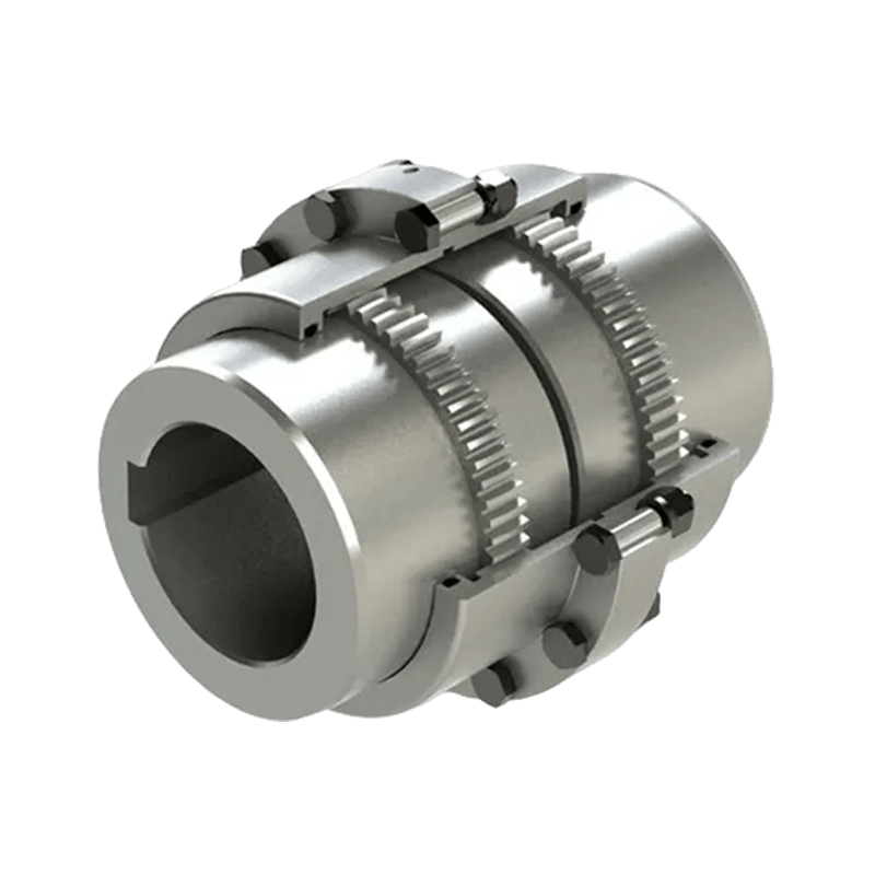
- 19 Product: GCJ Connected to intermediate shaft drum gear coupling(Q/YG 13015X-2018)
The GCJ intermediate-shaft drum gear coupling is a heavy-duty mechanical transmission component developed for industrial systems in which two shaft ends are separated by a considerable distance. Manufactured according to Q/YG 13015X-2018, this coupling combines crowned-tooth gear engagement with an intermediate shaft to transmit high torque while accommodating installation and operating misalignment.
Unlike a simple rigid flange connection, the GCJ design allows connected shafts to operate with controlled angular, radial, and axial displacement. Unlike many short-length flexible couplings, it is specifically configured for long-distance shaft arrangements. This makes it suitable for large and complex machinery used in metallurgy, mining, lifting, ports, paper production, water equipment, and other demanding industrial sectors.
The coupling belongs to the category of flexible couplings with non-elastic elements. Its flexibility is primarily achieved through the geometry and meshing action of the crowned gear teeth rather than through a rubber, polyurethane, or other elastomeric insert. The intermediate shaft extends the connection between the two coupling halves and provides valuable flexibility in equipment layout.
With nominal torque ratings from 6.3 kN·m to 3150 kN·m, the GCJ series covers a broad range of applications. The product family includes models GCJ1 through GCJ23, with shaft-hole options and dimensional variations selected according to the required torque, shaft diameter, connection arrangement, and intermediate-shaft length.
Product Overview
A conventional coupling normally connects two closely positioned shafts. However, many industrial machines cannot place their driving and driven shafts side by side. Long conveyor systems, rolling equipment, large lifting mechanisms, transport machinery, and certain process lines may require a shaft connection across a significant span.
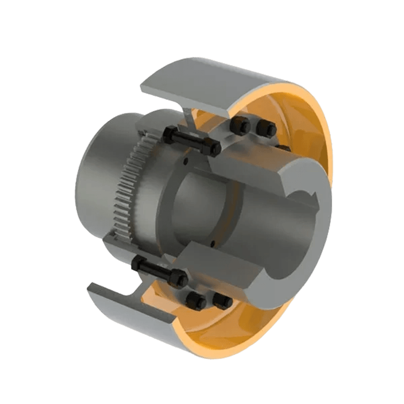
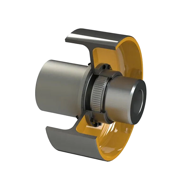
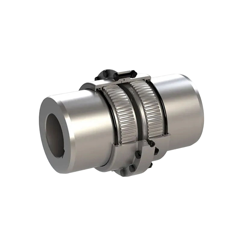
The GCJ coupling addresses this requirement by placing an intermediate shaft between two crowned-tooth gear coupling assemblies. Each assembly consists generally of an external-toothed hub and an internal-toothed sleeve or gear ring. The external and internal teeth engage while allowing limited relative movement between the shafts.
The intermediate shaft can be manufactured in a length appropriate to the equipment layout. The standard dimensional data identifies a minimum intermediate-shaft length, while additional length can be accommodated under the relevant design conditions. Because the intermediate shaft is integrated into a modular coupling arrangement, the designer gains more freedom when positioning motors, gear reducers, drums, rolls, or other driven equipment.
The main purpose of the GCJ structure is not simply to bridge a gap. It must transmit torque reliably, tolerate expected displacement, maintain tooth contact, protect connected equipment, and remain serviceable throughout repeated operating cycles. The product is therefore designed as a complete mechanical system rather than as an ordinary shaft extension.
Its main functional characteristics include:
• High torque transmission through steel gear-tooth engagement.
• Compensation for angular, radial, and axial shaft displacement.
• Suitability for medium- and long-distance shaft connections.
• A modular structure that simplifies installation and maintenance.
• Broad model coverage for small, medium, and very large industrial drives.
• Compatibility with cylindrical and flat-bore shaft arrangements.
• Grease lubrication for the crowned-tooth engagement surfaces.
• Engineering support for standard and customized coupling requirements.
Operating Principle of the Crowned-Tooth Gear Connection
The operating principle of a drum gear coupling depends on the interaction between crowned external teeth and matching internal teeth. The tooth surfaces are formed with a controlled crown or barrel shape. This geometry allows the teeth to continue transmitting torque when the connected shafts are not perfectly collinear.
In a rigid gear connection, even a small angular deviation could concentrate the load at one edge of the teeth. Such concentration may lead to excessive wear, pitting, noise, or premature failure. In a crowned-tooth design, the tooth curvature allows contact to move within a controlled area as the shafts change position. The result is improved contact behavior under angular displacement.
The gear teeth transmit torque through multiple engaged surfaces. Compared with a flexible coupling that relies on a single elastomeric element, a gear coupling can provide high torque capacity within a relatively compact radial envelope. This characteristic is particularly useful in heavy machinery, where torque levels are high and available installation space may be restricted.
The gear mesh also enables limited radial movement. As the intermediate shaft and connected equipment respond to operating loads, thermal effects, foundation movement, or installation tolerance, the crowned teeth can accommodate the resulting displacement within the allowable design range.
Axial movement can likewise be managed by the coupling arrangement, depending on the specific design and installation conditions. The coupling should not be regarded as a substitute for correct alignment, but it provides an important margin of tolerance that reduces the harmful effects of unavoidable displacement.
Because the coupling uses metallic gear elements rather than flexible rubber components, its performance is not dependent on the same type of elastomer aging, swelling, hardening, or tearing that can affect rubber-based couplings. Correct lubrication, alignment, sealing, and inspection remain essential, but the load-transmitting element is designed for severe mechanical service.
Why the Intermediate Shaft Matters
The intermediate shaft is the defining feature of the GCJ series. It creates a transmission bridge between two coupling halves and makes it possible to connect equipment that is separated by a substantial distance.
This arrangement offers several practical advantages. First, it provides greater freedom when designing the machine layout. A motor or gearbox does not need to be located immediately adjacent to the driven shaft. The equipment can be arranged to accommodate structural frames, guards, drums, rolls, bearings, hydraulic components, or maintenance access.
Second, the intermediate shaft can help distribute the connection into manageable modules. Instead of attempting to install one oversized coupling around a difficult shaft arrangement, technicians can work with two coupling ends and an intermediate member. This may simplify transportation, positioning, assembly, and replacement.
Third, the intermediate-shaft configuration is well suited to machinery where the drive and driven components are supported by separate bearing housings. Each end of the coupling can be aligned with its respective shaft, while the gear engagement provides the required flexibility between the two ends.
Fourth, the intermediate shaft can be designed for the required span and rotational conditions. The length, diameter, balance, and connection details must be considered together. For high-speed applications or unusually long arrangements, torsional vibration, critical speed, shaft deflection, and dynamic balance should be evaluated by qualified engineers.
The GCJ is therefore more than a standard short coupling with an extended spacer. Its intermediate shaft, gear hubs, sleeves, lubrication arrangement, and connection dimensions must function as a coordinated transmission system.
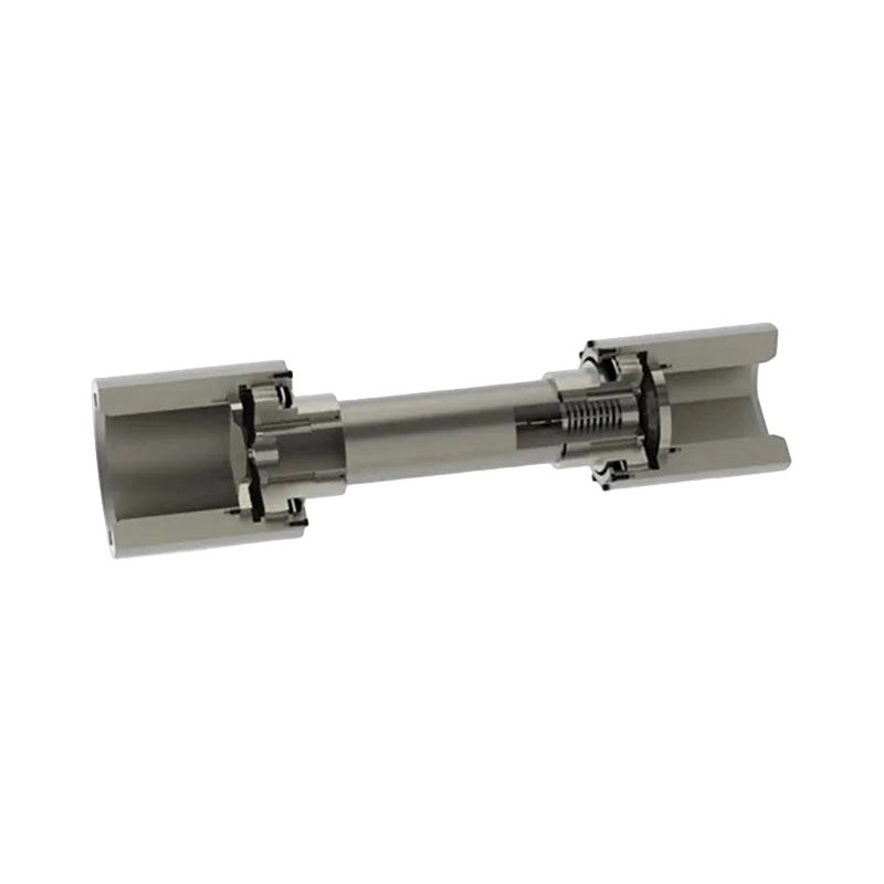
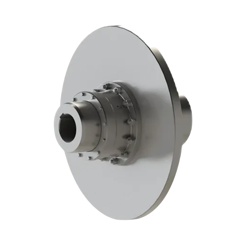
GCJ Connected to intermediate shaft drum gear coupling(Q/YG 13015X-2018)
Key Technical Advantages
High Torque Capacity
The GCJ series covers nominal torque values from 6.3 kN·m for GCJ1 to 3150 kN·m for GCJ23. This wide range allows the product family to serve applications from moderate industrial drives to extremely heavy-duty transmission systems.
Torque is transmitted through robust metallic gear teeth and hubs. The load is distributed across multiple teeth rather than concentrated in a single flexible insert. This construction is advantageous in applications with high starting loads, frequent load changes, heavy rotating masses, or continuous operation under severe conditions.
Actual coupling selection should consider more than nominal torque. Starting torque, shock loading, service factor, reversing operation, braking torque, speed, duty cycle, temperature, shaft diameter, and alignment conditions must all be reviewed. A coupling that appears adequate based only on average running torque may be under-sized for a machine with high acceleration or impact loads.
Displacement Compensation
The crowned-tooth design compensates for a degree of angular and radial misalignment while maintaining effective torque transmission. This is one of the most important advantages of the GCJ coupling over a rigid connection.
Misalignment can arise from inaccurate installation, foundation settlement, bearing clearance, shaft deflection, thermal expansion, manufacturing tolerances, or changes in load. By accommodating controlled displacement, the coupling reduces the transfer of excessive reaction forces to shafts, bearings, gearboxes, and other connected components.
Displacement compensation does not eliminate the need for alignment. Excessive misalignment increases tooth sliding, edge loading, friction, heat generation, and wear. Correct installation remains the foundation of reliable service. The coupling should be used to accommodate expected movement, not to correct poor workmanship.
Long-Distance Layout Flexibility
The intermediate-shaft arrangement is more versatile than a compact coupling designed only for adjacent shafts. It can be adapted to different center distances and equipment configurations, subject to the standard dimensional limits and engineering verification.
This flexibility can reduce the need for major changes to an existing machine. In replacement projects, the GCJ can be specified according to the existing shaft positions, bore dimensions, and available installation envelope. In new equipment, it provides designers with more options for placing the drive unit and driven mechanism.
Stable Operation Under Industrial Loads
Heavy industrial equipment often experiences vibration, impact, fluctuating torque, and changes in operating alignment. The GCJ coupling is designed to maintain a stable gear connection under these conditions when correctly selected, lubricated, and installed.
The gear-tooth geometry helps maintain controlled contact as the shafts move relative to one another. The intermediate shaft also contributes to a structured and predictable transmission path. When the coupling is correctly balanced and supported by suitable bearings, it can contribute to smooth operation and reduced mechanical stress throughout the drive system.
Metallic Construction for Severe Environments
The coupling is manufactured from steel or alloy steel according to the required performance level and design specification. Metallic construction offers high strength, resistance to repeated torque loading, and good durability in industrial environments.
The product can be applied in areas exposed to dust, humidity, elevated temperature, and heavy mechanical contamination, provided that appropriate sealing, grease selection, surface protection, and maintenance procedures are used. Material selection and heat treatment can be adjusted for specific requirements such as increased wear resistance, impact resistance, or fatigue performance.
In contrast, certain flexible couplings that use polymeric elements may be more sensitive to temperature, ultraviolet exposure, chemical attack, or long-term material aging. A metal gear coupling can be a more suitable choice when high torque and severe environmental conditions are dominant design considerations.
Serviceability and Modular Maintenance
The GCJ structure is designed to support inspection, lubrication, and component replacement. Gear coupling operation depends heavily on maintaining an adequate lubricating film between the tooth surfaces. A service-friendly design makes it easier for maintenance personnel to access lubrication points and inspect seals, teeth, hubs, and fasteners.
Modular construction can reduce the time required for disassembly compared with a fully integrated, difficult-to-access shaft connection. This is especially valuable in continuous-process industries where unplanned downtime can cause substantial production losses.
Maintenance personnel should establish inspection intervals according to speed, load, environment, operating hours, and the consequences of failure. Grease condition, leakage, unusual noise, tooth wear, temperature rise, vibration, and fastener condition should be included in the maintenance program.
Comparison with Other Coupling Types
| Design consideration | GCJ intermediate-shaft drum gear coupling | Rigid flange coupling | Elastomeric coupling | Diaphragm coupling |
| Long-distance shaft connection | Well suited because of the intermediate shaft | Possible only with additional shaft structures | Usually limited to shorter connections | Possible in selected designs |
| Torque capacity | High to extremely high | High when alignment is precise | Low to medium, depending on element | Medium to high |
| Misalignment compensation | Angular, radial, and controlled axial displacement | Very limited | Good, depending on element design | Primarily angular and axial movement |
| Shock and vibration behavior | Metallic transmission with controlled flexibility | Transfers more load to connected equipment | Strong damping through the elastic element | Low inherent damping |
| Environmental resistance | Strong when material, seals, and grease are correctly selected | Strong but alignment-sensitive | May be affected by heat, chemicals, or aging | Generally strong, but fatigue must be evaluated |
| Maintenance focus | Tooth inspection, lubrication, sealing, and alignment | Alignment and fastener inspection | Element inspection and replacement | Diaphragm fatigue, bolts, and alignment |
Every coupling type has an appropriate application. The GCJ is not intended to replace every elastic, diaphragm, grid, or rigid coupling. Its advantage is strongest where high torque, long shaft spacing, controlled misalignment compensation, and metallic durability are required at the same time.
A rigid coupling may be simpler and less expensive where two shafts are perfectly aligned and no displacement is expected. However, rigid designs can impose substantial loads on bearings and shafts when alignment changes. An elastomeric coupling may provide superior damping for a compact motor-to-pump arrangement, but its torque capacity and environmental life may be limited in heavy-duty service.
A diaphragm coupling can provide high torsional stiffness and low maintenance in selected high-speed applications, but its allowable radial displacement, installation requirements, and long-distance configuration may differ from those of a drum gear coupling. The GCJ offers a robust alternative for equipment where gear-tooth load capacity and intermediate-shaft flexibility are central requirements.
Nominal Torque and Model Range
The GCJ model range contains 23 sizes. Nominal torque increases progressively across the series, allowing engineers to match the coupling to the required transmission duty without selecting an unnecessarily large component.
| Model | Nominal torque, kN·m | Typical cylindrical bore range, mm | Minimum intermediate-shaft length, mm | Approximate mass at minimum length, kg |
| GCJ1 | 6.3 | 60–80 | 500 | 46 |
| GCJ2 | 11.2 | 70–100 | 500 | 76 |
| GCJ3 | 18 | 80–110 | 600 | 105 |
| GCJ4 | 25 | 80–125 | 600 | 140 |
| GCJ5 | 31.5 | 90–140 | 600 | 200 |
| GCJ6 | 50 | 110–160 | 800 | 280 |
| GCJ7 | 63 | 140–190 | 800 | 380 |
| GCJ8 | 80 | 160–200 | 1000 | 480 |
| GCJ9 | 100 | 170–220 | 1000 | 550 |
| GCJ10 | 125 | 190–240 | 1000 | 720 |
| GCJ11 | 200 | 190–260 | 1200 | 1110 |
| GCJ12 | 315 | 240–300 | 1200 | 1480 |
| GCJ13 | 450 | 280–340 | 1400 | 2020 |
| GCJ14 | 560 | 300–360 | 1500 | 2600 |
| GCJ15 | 710 | 340–400 | 1500 | 3300 |
| GCJ16 | 900 | 360–420 | 1600 | 4300 |
| GCJ17 | 1120 | 400–460 | 1800 | 5500 |
| GCJ18 | 1250 | 420–500 | 2000 | 6700 |
| GCJ19 | 1600 | 440–530 | 2000 | 8350 |
| GCJ20 | 2000 | 450–560 | 2000 | 9500 |
| GCJ21 | 2240 | 480–600 | 2500 | 11500 |
| GCJ22 | 2800 | 530–630 | 2500 | 12600 |
| GCJ23 | 3150 | 560–670 | 2500 | 17900 |
The values in this summary are representative data extracted from the product specifications. Detailed selection must use the complete dimensional drawing and the exact shaft-hole arrangement. Some models include multiple bore sizes, and certain bore combinations have different overall dimensions. The mass values are approximate and are based on specified assumptions concerning shaft-hole diameter and intermediate-shaft length.
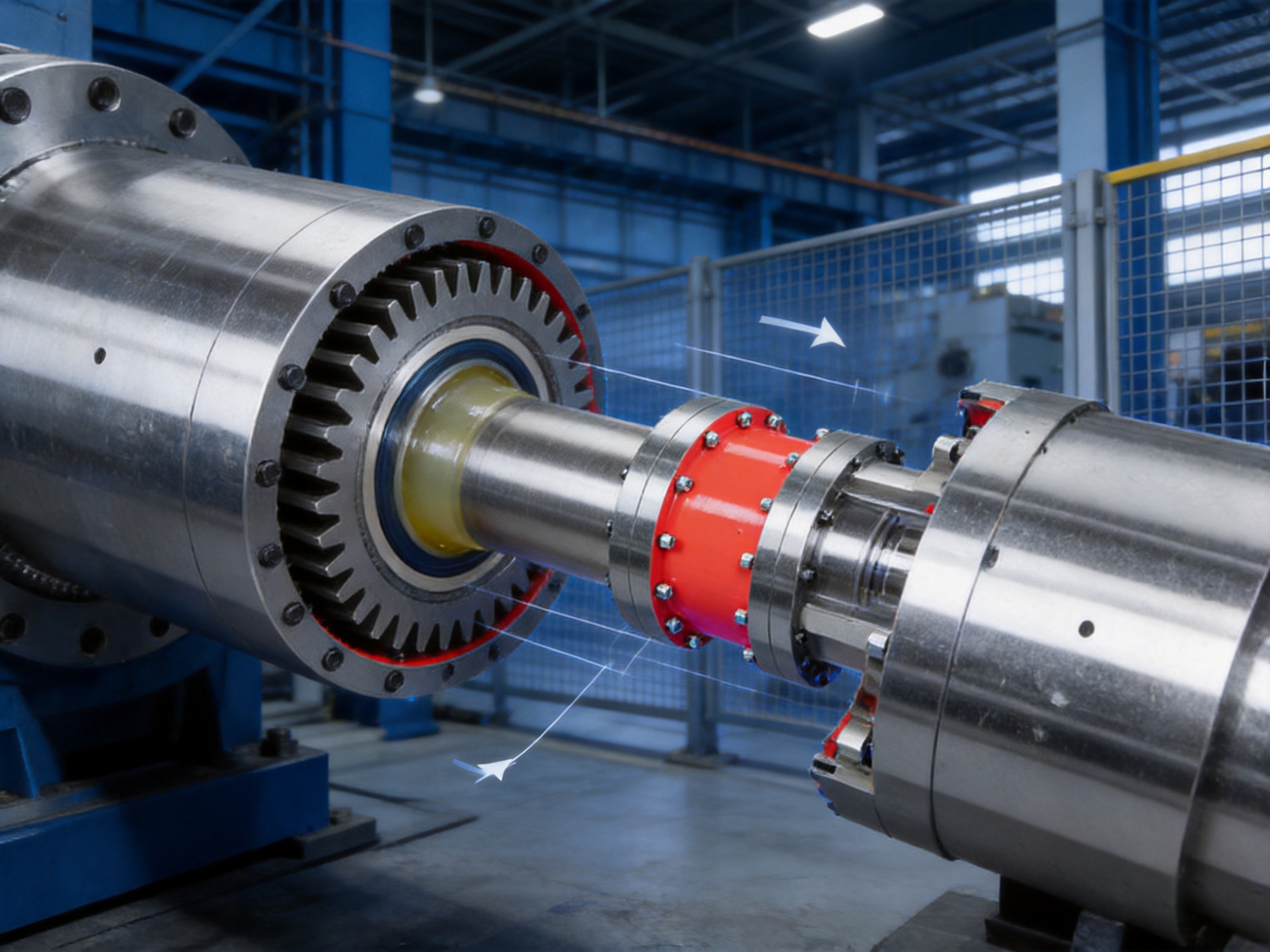
Dimensional and Shaft-Hole Options
The standard product data includes cylindrical shaft-hole dimensions and flat-bore shaft-hole dimensions. Under normal conditions, the active end of the coupling uses a cylindrical shaft hole, while the driven end uses a flat bore. If required by the equipment, both ends can be manufactured with cylindrical shaft holes.
This arrangement allows the coupling to match different shaft-end configurations. A cylindrical bore is commonly used where a shaft is installed through a conventional keyed or interference-fit connection. A flat bore can be selected when the driven shaft has a corresponding flat or special profile arrangement.
For flat-bore shaft holes, the specified limit tolerance of d₂ and B is H9. This tolerance information is important during shaft and coupling design because the bore condition influences fit, load transfer, installation method, and service reliability.
Models GCJ1 through GCJ5 may be selected according to GB/T 3852 when a Y-type shaft extension is required. Engineers should confirm the exact shaft extension, keyway, fit, and dimensional requirements before production.
The complete specification includes dimensions identified as D₁, D₂, D₃, L₁, L₂, L₃, L₄, L₅, and L₆. These dimensions define the coupling envelope, shaft connection, intermediate-shaft arrangement, and installation space. The minimum L₅ dimension is especially relevant when determining the shortest permissible center distance between the coupling ends.
For a customized coupling, the design team may need the following information:
• Driving and driven shaft diameters.
• Shaft-hole type and keyway requirements.
• Distance between shaft ends.
• Required nominal and peak torque.
• Operating speed and rotation direction.
• Starting, stopping, braking, and reversing conditions.
• Expected angular, radial, and axial displacement.
• Ambient temperature and environmental contamination.
• Available installation and removal clearance.
• Required balancing grade and vibration limits.
• Preferred material, coating, seal, and lubrication requirements.
Manufacturing Process and Engineering Quality
The performance of a large gear coupling depends on much more than its nominal dimensions. Tooth accuracy, concentricity, material quality, heat treatment, balance, surface finish, sealing, and assembly control all affect operating life. The manufacturing process must therefore be organized around the complete transmission function.
Engineering Design
The design process begins with the operating data supplied by the customer. Engineers calculate the required torque capacity and apply an appropriate service factor based on the driven equipment and duty cycle. Shaft diameter, bore length, key connection, intermediate-shaft span, rotational speed, and allowable displacement are then reviewed together.
For long intermediate shafts, the engineering assessment should include torsional stiffness, bending strength, shaft deflection, critical speed, bearing arrangement, and dynamic balance. These factors become increasingly important as the shaft becomes longer or the rotational speed increases.
Three-dimensional modeling and detailed drawings can be used to confirm the gear mesh, housing envelope, fastener positions, lubrication access, seal arrangement, and maintenance clearance. This reduces the risk of interference during installation and allows non-standard requirements to be addressed before machining begins.
Material Preparation
High-quality steel or alloy steel is selected according to the required strength, toughness, wear resistance, and environmental conditions. Material certificates and traceability records support quality control from raw material receipt through final inspection.
Large coupling components require careful control of material uniformity. Forged or properly prepared steel blanks can provide a sound foundation for hubs, sleeves, flanges, and intermediate shafts. The selected material must be compatible with the intended heat treatment and final mechanical properties.
Precision Machining
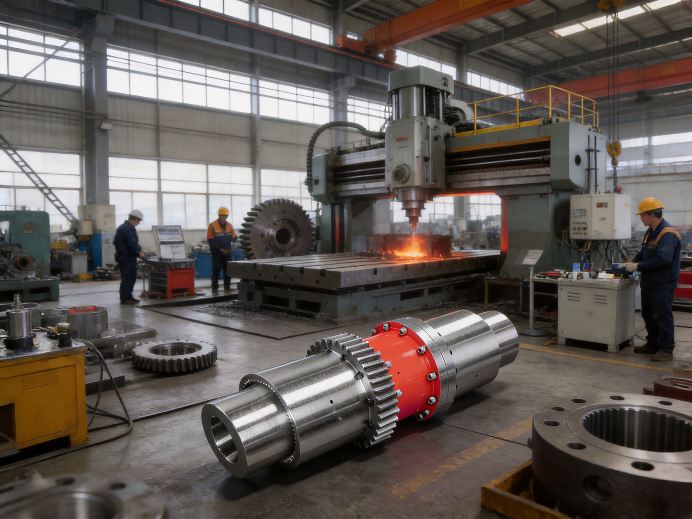
Large turning and milling equipment is used to produce the principal coupling components. The machining process controls outside diameters, bore dimensions, flange faces, shoulder locations, tooth reference surfaces, and concentricity.
Gear teeth require particularly careful machining. The internal and external tooth profiles must match correctly to provide smooth engagement and controlled displacement compensation. Tooth spacing, profile accuracy, lead accuracy, and surface finish influence contact pressure, noise, wear, and service life.
Keyways, flat bores, bolt holes, retaining features, lubrication passages, and seal grooves are machined according to the approved drawing. For large components, process planning is important because distortion, tool deflection, and workpiece weight can affect final accuracy.
Heat Treatment and Surface Performance
Heat treatment may be applied to achieve the required balance of hardness, toughness, fatigue strength, and wear resistance. The specific process depends on the material, component size, tooth design, and operating duty.
Gear teeth benefit from a controlled surface condition that resists contact fatigue and sliding wear while retaining adequate toughness beneath the working surface. Hubs and intermediate shafts must also withstand repeated torque and bending loads without brittle failure.
After heat treatment, components may require finishing operations to restore dimensional accuracy. Inspection can include hardness testing, dimensional verification, and checks for distortion or surface defects.
Assembly and Functional Inspection
During assembly, the relationship between the gear hubs, sleeves, intermediate shaft, seals, fasteners, and lubrication components is verified. Proper assembly ensures that the gear teeth engage within the intended position and that the housing or sleeve can retain lubricant during operation.
Inspection procedures may include dimensional checks, bore measurement, runout inspection, tooth-contact verification, fastener inspection, balance evaluation, and visual examination. Depending on the customer’s requirements, non-destructive testing can be used to identify cracks or other internal and surface defects in critical components.
The final quality process is designed to ensure that the delivered coupling conforms to the approved technical specification. This approach supports consistent production across standard models while still allowing customization for special equipment.
Manufacturing Strengths of the Supplier
Zhongye Heavy Industry Technology (Zhenjiang) Co., Ltd. integrates product research and development, manufacturing, sales, and technical service. The company serves industries including metallurgical equipment, mining machinery, water equipment, lifting systems, paper machinery, port equipment, and other industrial applications where reliable power transmission is essential.
The company’s manufacturing base includes a heavy workshop, precision workshop, office and engineering facilities, warehouse space, and supporting infrastructure. The reported new workshop covers approximately 16,463.52 square meters, including a 5,500-square-meter heavy workshop and a 4,600-square-meter precision workshop.
This combination of heavy and precision manufacturing capability is important for large gear couplings. Heavy equipment is required to handle large forgings, high-mass intermediate shafts, and oversized housings. Precision equipment is needed to control gear tooth geometry, bore tolerances, concentricity, and final assembly accuracy.
The supplier’s product range includes toothed couplings, elastic sleeve pin couplings, elastic pin couplings, gear couplings with elastic pins, universal couplings, tire couplings, jaw couplings, star couplings, diaphragm couplings, drum couplings, grid couplings, Oldham couplings, flange couplings, clamp-shell couplings, roller-chain couplings, safety couplings, and customized non-standard couplings.
This broad product experience supports practical coupling selection. Customers can discuss the complete transmission system rather than evaluating the GCJ product in isolation. When a different coupling principle is more suitable, the supplier can review alternative designs or develop a customized solution.
The company emphasizes research and development, production guarantees, testing facilities, quality control, complete model specifications, technical support, non-standard design, and after-sales service. These capabilities are particularly valuable for large industrial couplings, where correct design and installation support can be as important as the component itself.
Quality management is supported by ISO 9001-related systems and documented production controls. Customers requiring project documentation may request drawings, inspection records, material information, dimensional reports, and other quality documents according to the purchase specification.
Application Areas
Metallurgical Equipment
Steel mills and non-ferrous metal processing plants use high-torque drives for rolling, conveying, lifting, shearing, coiling, and material handling. These machines may experience rapid load changes, shock loading, high temperatures, scale, dust, and limited maintenance windows.
The GCJ coupling is suitable for transmission arrangements where the motor or gearbox is separated from the driven roll, drum, or other rotating component. Its metallic gear construction and displacement compensation help accommodate the demanding operating conditions of metallurgical equipment.
Mining Machinery
Mining equipment often operates under heavy loads and harsh environmental conditions. Crushers, conveyors, hoists, feeders, and processing machinery may require high torque and reliable operation in the presence of dust, vibration, and impact.
The intermediate shaft provides layout flexibility in large mining installations. Correct sealing and grease maintenance are especially important in dusty environments, because contamination can accelerate tooth wear and degrade the lubricant.
Lifting and Hoisting Equipment
Large cranes, hoists, winches, and lifting mechanisms require dependable torque transmission and careful control of shock loads. Coupling selection must consider acceleration, braking, load reversal, emergency stopping, and the consequences of mechanical failure.
The GCJ can be integrated into heavy lifting systems when its torque rating, speed, bore arrangement, and safety requirements are correctly verified. For critical lifting applications, the overall mechanical design should include suitable guarding, inspection, braking, and overload protection.
Port and Transport Equipment
Port machinery often combines long transmission paths with high load cycles. Ship loaders, unloaders, conveyors, winches, and transfer systems may require a coupling that can bridge separated shafts while tolerating operational movement.
The GCJ design can help equipment designers position drive units and driven mechanisms around structural constraints. Corrosion protection, sealing, and lubrication should be selected for the local marine or coastal environment.
Paper and Process Machinery
Paper machinery requires stable rotating performance and accurate transmission across rolls, dryers, calendars, and other process units. Depending on the specific machine, the coupling may be selected for its torque capacity, long-distance configuration, or ability to accommodate thermal and installation displacement.
Operating speed and balance are important in paper applications. The intermediate shaft must be evaluated for dynamic behavior, and the complete assembly should be installed according to the approved alignment and balancing requirements.
Water and General Industrial Equipment
Water equipment, pumps, mixers, treatment machinery, and general process systems may use shaft connections with different distances and alignment conditions. The GCJ offers a robust option where a standard compact coupling does not provide sufficient torque or span flexibility.
Installation Guidelines
Before installation, verify the model, bore dimensions, shaft-end configuration, rotation direction, intermediate-shaft length, fasteners, seals, and lubrication components. Confirm that the coupling matches the approved drawing and that no component has been damaged during transportation.
Inspect the driving and driven shafts for burrs, corrosion, dirt, damaged keyways, or dimensional deviations. Shaft surfaces should be clean and free from oil or debris where a specific interference or keyed fit is required. Do not force components into position with uncontrolled impact, as this can damage bearings, seals, gear teeth, or machined faces.
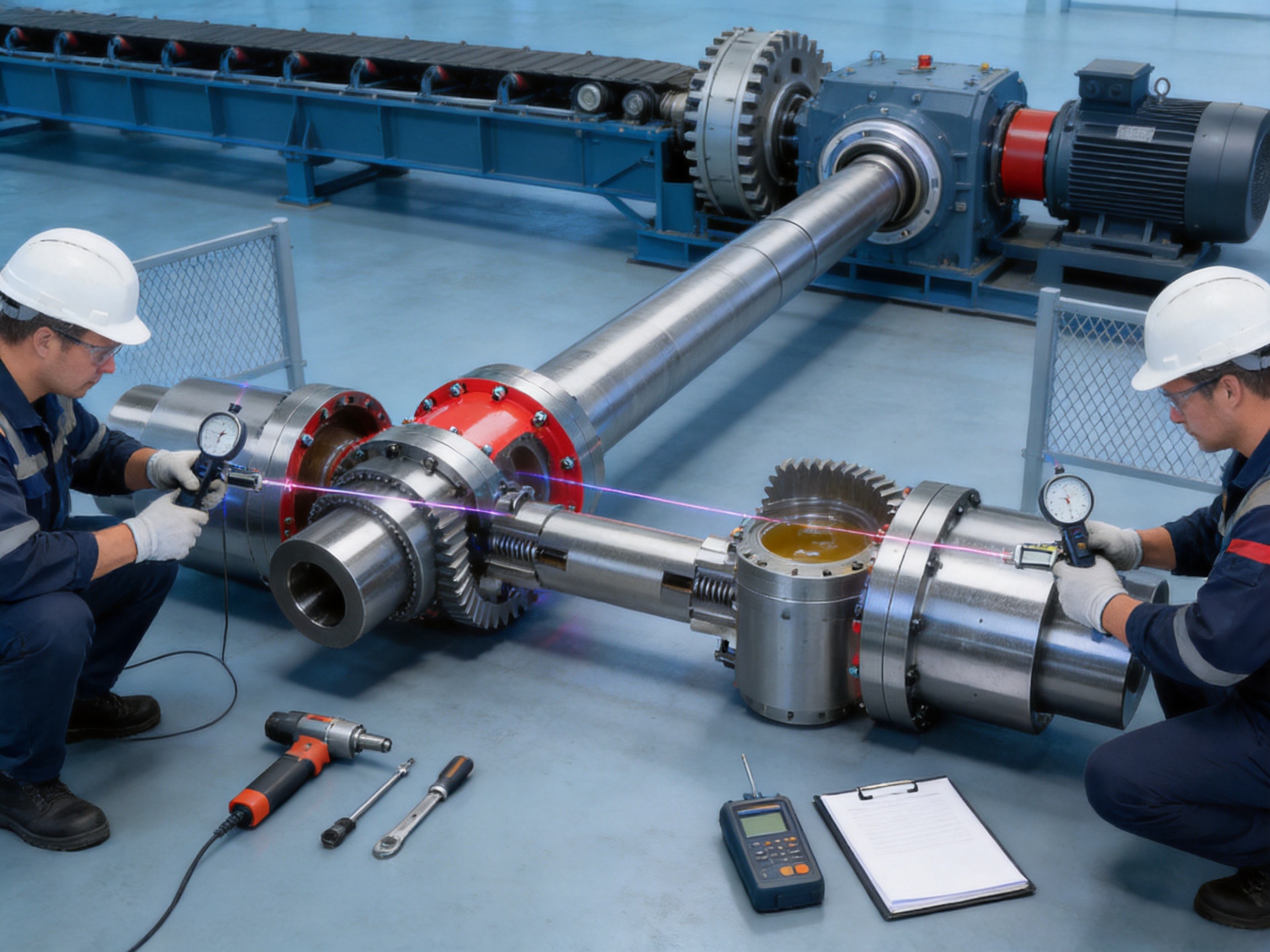
Measure shaft alignment using suitable instruments. Angular and parallel offset should be within the allowable limits specified for the coupling and the machine. Check the axial position and ensure that the coupling has the required clearance for thermal movement and operational displacement.
Install keys, locking components, bolts, and retaining parts according to the approved assembly procedure. Fasteners should be tightened using the specified sequence and torque. If the coupling uses a special fit or hydraulic installation method, follow the relevant technical instructions.
Fill the gear chambers with the recommended grease. The lubricant must be compatible with the operating speed, temperature, load, seals, and gear material. Avoid mixing incompatible grease types. Excessive grease can increase churning and temperature, while insufficient grease can cause rapid tooth wear.
After assembly, rotate the shaft manually where possible to identify interference or abnormal resistance. Run the equipment initially at low speed or under no-load conditions if the machine design permits. Observe vibration, noise, temperature, grease leakage, and coupling behavior before applying full operating load.
Appropriate guarding must be installed before normal operation. Rotating couplings present serious entanglement and impact hazards, and personnel should never approach an exposed coupling while the machine is running.
Maintenance and Service Recommendations
Regular lubrication is the most important routine maintenance activity for a gear coupling. The maintenance interval depends on speed, torque, environment, duty cycle, seal performance, and operating temperature. A contaminated or degraded grease film can significantly reduce tooth life.
During inspection, check for grease leakage around seals and covers. Leakage may indicate seal wear, excessive internal pressure, damaged sealing surfaces, incorrect assembly, or overfilling. If grease escapes, contaminants may enter and accelerate tooth wear.
Listen for unusual clicking, rattling, grinding, or cyclic noise. Such sounds may indicate tooth damage, insufficient lubrication, excessive misalignment, loose fasteners, or an intermediate-shaft problem. Vibration monitoring can help identify developing issues before visible damage occurs.
Inspect the tooth surfaces for pitting, scoring, polishing, uneven contact, plastic deformation, or abnormal wear. Tooth wear concentrated at one end or one side may indicate excessive angular or parallel misalignment. The cause should be corrected rather than simply replacing the worn coupling.
Check the intermediate shaft for bending, cracks, corrosion, or damage near keyways and flange connections. Long shafts should also be checked for balance and support condition. Bearing wear or looseness can create displacement beyond the coupling’s intended capacity.
After maintenance, confirm that all covers, seals, bolts, keys, and guards have been correctly reinstalled. Record inspection findings, lubricant additions, component replacements, vibration readings, and operating conditions. A documented maintenance history supports more accurate service planning.
Selection Procedure
Begin by calculating the actual transmitted power and speed. Torque can be determined from the power and rotational speed, but the resulting value must be increased by an appropriate service factor for the equipment duty.
Next, compare the calculated design torque with the nominal torque of the available GCJ models. Select a model that provides adequate capacity without exceeding the shaft-hole and installation constraints.
Confirm that the required shaft diameters fall within the model’s bore range. Review whether the driving end requires a cylindrical bore, whether the driven end requires a flat bore, or whether both ends should be cylindrical.
Measure the distance between shaft ends and compare it with the minimum intermediate-shaft length and the permitted design range. The shaft span must also be checked for bending, torsional vibration, critical speed, and support requirements.
Evaluate the expected angular, radial, and axial displacement. Include thermal expansion, bearing movement, shaft deflection, foundation behavior, and installation tolerances. If the displacement exceeds standard capabilities, a customized design should be considered.
Review the environment. Dust, water, chemicals, high temperature, outdoor exposure, and corrosive atmosphere may influence material, coating, sealing, grease, and maintenance intervals.
Finally, verify speed, balance, safety requirements, guarding, installation access, and maintenance space. A technically correct coupling can still be unsuitable if it cannot be installed, lubricated, inspected, or removed safely.
Customization Capabilities
Industrial machinery frequently requires coupling dimensions that are not covered by a standard catalog model. The supplier supports customized coupling design and manufacturing for non-standard shaft spacing, bore dimensions, intermediate-shaft lengths, connection methods, materials, coatings, and environmental conditions.
A customized design may include a special cylindrical bore, a modified flat bore, alternative keyway dimensions, an extended intermediate shaft, a different flange arrangement, enhanced sealing, corrosion-resistant treatment, or special balancing requirements.
Customization should begin with complete equipment information. Drawings of the connected shafts, shaft-end details, bearing locations, available space, and installation method help prevent design conflicts. Operating data should include maximum torque, normal torque, speed, load spectrum, startup behavior, braking requirements, and expected misalignment.
For large or high-speed applications, engineering analysis may be required to verify shaft stress, gear-tooth loading, thermal behavior, dynamic balance, and critical speed. The final design should be approved before manufacturing begins.
Reliability and Lifecycle Value
The purchase price of a coupling is only one part of its total cost. Downtime, replacement labor, damage to connected equipment, lubricant consumption, inspection time, and production interruption can have a greater economic effect than the initial component cost.
The GCJ design can provide lifecycle value by combining high torque capacity with serviceable construction. Its crowned-tooth geometry helps protect connected equipment from the effects of controlled misalignment, while the intermediate shaft allows a practical arrangement in long-distance drives.
Metallic gear engagement can also offer a long service life when the coupling is correctly selected and maintained. The absence of an elastomeric torque element reduces exposure to some common polymer-related failure modes. However, gear couplings still require proper lubrication, sealing, alignment, and inspection.
Reliable performance is therefore the result of the product design and the complete application process. Engineering selection, accurate machining, controlled assembly, appropriate installation, and planned maintenance must work together.
Frequently Asked Questions
What is a GCJ intermediate-shaft drum gear coupling?
It is a flexible metallic coupling that uses crowned-tooth gear engagement at both ends of an intermediate shaft. It transmits torque between separated shafts while accommodating controlled angular, radial, and axial displacement.
What standard does the GCJ coupling follow?
The product is identified according to Q/YG 13015X-2018. Models GCJ1 through GCJ5 may also be selected according to GB/T 3852 when a Y-type shaft extension is required, subject to confirmation of the exact design.
What is the torque range?
The standard GCJ series covers nominal torque from 6.3 kN·m to 3150 kN·m, across models GCJ1 through GCJ23.
Can the coupling connect long-distance shafts?
Yes. The intermediate shaft is specifically intended to connect shaft ends separated by a considerable distance. The actual span must be checked against the applicable model dimensions and verified for strength, balance, deflection, and dynamic behavior.
Does the coupling use rubber or polymer elements?
The GCJ is classified as a flexible coupling with non-elastic elements. Its flexibility is primarily provided by crowned-tooth gear geometry and the intermediate-shaft arrangement rather than by a rubber or polymer torque-transmitting element.
Can both shaft holes be cylindrical?
Yes. Under normal conditions, one end may use a cylindrical shaft hole and the other a flat bore, but both ends can be cylindrical when required by the equipment configuration.
What tolerance applies to the flat bore?
The product information specifies an H9 limit tolerance for d₂ and B on flat-bore shaft holes. The final tolerance and fit should be confirmed against the approved technical drawing.
What materials are used?
The coupling is manufactured from steel or alloy steel selected according to torque, wear, fatigue, environmental, and customization requirements. Heat treatment and surface finishing may be applied as needed.
How is the coupling lubricated?
The crowned-tooth gear engagement is lubricated with grease. The grease type, filling quantity, sealing arrangement, and maintenance interval should be selected according to operating speed, temperature, load, and environment.
Is the coupling maintenance-free?
No. Although the metallic construction can provide long service, the coupling requires inspection, lubrication, seal checks, alignment verification, and examination of tooth surfaces and fasteners.
What information is needed for product selection?
Important information includes torque, speed, shaft diameters, shaft-hole type, shaft-end dimensions, distance between shafts, rotation direction, misalignment, environmental conditions, duty cycle, installation space, and any special material or balancing requirements.
Can non-standard couplings be manufactured?
Yes. Customized designs can be developed for special bore dimensions, shaft spans, intermediate-shaft lengths, materials, coatings, seals, connection methods, and application conditions.
Which industries use this type of coupling?
Typical industries include metallurgy, mining, lifting, ports, paper production, water equipment, conveyors, process machinery, and other heavy industrial applications.
How does the GCJ compare with an elastomeric coupling?
The GCJ generally offers higher metallic torque capacity and greater suitability for long-distance shaft connections. An elastomeric coupling may provide more inherent damping in compact systems. The best choice depends on torque, speed, displacement, shock, temperature, and maintenance requirements.
How does the coupling protect bearings?
By accommodating controlled shaft displacement, the crowned teeth can reduce the transfer of excessive alignment-related forces to connected bearings and equipment. This benefit depends on correct alignment and operation within the coupling’s allowable displacement limits.
Conclusion
The GCJ connected-to-intermediate-shaft drum gear coupling is engineered for demanding industrial power transmission where a short, compact coupling is not sufficient. Its crowned-tooth gear structure provides high torque transmission and controlled displacement compensation, while the intermediate shaft creates a practical solution for medium- and long-distance shaft connections.
The series provides 23 standard models with nominal torque ratings from 6.3 kN·m to 3150 kN·m. Cylindrical and flat-bore options, multiple shaft diameters, modular construction, grease lubrication, and customization support make the product adaptable to a wide range of machinery.
Its advantages over rigid couplings include greater misalignment accommodation and reduced stress transfer. Compared with many elastomeric couplings, it offers higher metallic load capacity and stronger suitability for severe mechanical service. Compared with compact standard gear couplings, the intermediate-shaft design provides greater layout flexibility and a longer transmission span.
The product’s reliability is supported by the supplier’s integrated capabilities in research and development, heavy fabrication, precision machining, assembly, testing, quality management, and technical service. With appropriate selection, installation, lubrication, alignment, and inspection, the GCJ coupling can provide a durable and efficient connection for large industrial drive systems.
References
Q/YG 13015X-2018, Technical Standard for GCJ Intermediate-Shaft Drum Gear Couplings.
GB/T 3852, Basic Parameters and Dimensions of Couplings and Shaft Extensions.
ISO 9001, Quality Management Systems Requirements.
General engineering principles for gear coupling selection, alignment, lubrication, and maintenance.
Manufacturer-provided GCJ product specifications, dimensional tables, application information, and technical notes.
Industrial coupling design practices for metallurgy, mining, lifting, paper, port, water, and process equipment.
Product: GCJ Connected to intermediate shaft drum gear coupling(Q/YG 13015X-2018)
- Quick Links
- About
- Products
- Our Service
- News & Events
- Contact
- Products Series
- Flexible Couplings with Non-Elastic Elements
- Flexible Couplings with Metal Elastic Elements
- Flexible Couplings with Non-Metallic Elastic Elements
- Safety Coupling
- Rigid Coupling
- Contact Us
- Tel : +86 511 8572 3800 +86 511 8572 3900
- Mobile : +86 15106109009
- Email : sales@couplingzy.com
- Add:No.1 Zhongye Yingbin Avenue, Gaozi Street, Dantu Economic Development Zone, Zhenjiang City, Jiangsu Province, China.


