:+86 15106109009
:sales@couplingzy.com


 English
  русский
  Español
  عربى
عربى  Português
  Deutsch
  Türk
Türk  Indonesia

MP Diaphragm Coupling for High-Precision, High-Torque Power Transmission
Content
- 1 1. What Is an MP Diaphragm Coupling?
- 2 2. Working Principle of the Diaphragm Assembly
- 3 3. Main Advantages of the MP Diaphragm Coupling
- 3.1 3.1 High Torsional Rigidity
- 3.2 3.2 Compensation for Multiple Types of Misalignment
- 3.3 3.3 Lubrication-Free Operation
- 3.4 3.4 Wide Temperature Capability
- 3.5 3.5 Corrosion and Harsh-Environment Suitability
- 3.6 3.6 High-Speed Performance and Balance
- 3.7 3.7 Compact and Relatively Simple Construction
- 3.8 3.8 High Transmission Efficiency
- 4 4. Comparison with Other Coupling Technologies
- 5 5. MP Series Product Range and Technical Parameters
- 6 6. How to Select the Correct MP Coupling
- 7 7. Manufacturing Quality and Engineering Strengths
- 8 8. Industrial Applications
- 9 9. Installation Recommendations
- 10 10. Maintenance and Inspection
- 11 11. Safety Considerations
- 12 12. Why Choose Zhongye Heavy Industry Technology?
- 13 13. Frequently Asked Questions
- 13.1 Q1: What type of coupling is the MP diaphragm coupling?
- 13.2 Q2: Does the MP diaphragm coupling require lubrication?
- 13.3 Q3: Can it replace a snake spring coupling?
- 13.4 Q4: Can it replace a gear coupling?
- 13.5 Q5: What is the temperature range of the MP coupling?
- 13.6 Q6: What torque range is available?
- 13.7 Q7: What information is needed for selection?
- 13.8 Q8: Is the coupling suitable for high-speed machinery?
- 13.9 Q9: Can the MP coupling be customized?
- 13.10 Q10: How often should the coupling be inspected?
- 13.11 Q11: Can the coupling compensate for poor alignment?
- 13.12 Q12: Is the MP diaphragm coupling suitable for corrosive environments?
- 14 14. Conclusion
- 15 References
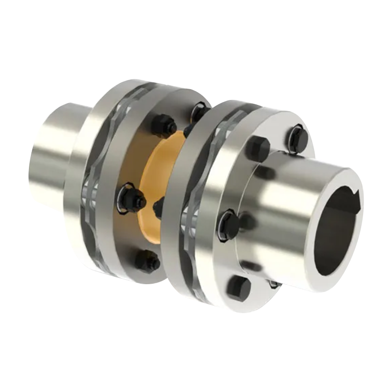
- 16 Product: MP diaphragm coupling(Q/YP 21001X-2018)
Reliable shaft connection is essential to the performance, safety, and operating life of industrial machinery. In equipment such as rolling mills, mining machines, pumps, compressors, generators, marine drives, paper machines, lifting systems, and process equipment, the coupling must transfer torque accurately while accommodating the inevitable alignment errors between connected shafts. It must also withstand vibration, speed variation, temperature changes, corrosive surroundings, and repeated starting and stopping.
The MP diaphragm coupling, manufactured in accordance with the Q/YP 21001X-2018 standard, is designed for these demanding conditions. It is a metal elastic element coupling that uses a precision diaphragm assembly rather than an elastomer, gear tooth mesh, or snake spring. The diaphragm group is formed from multiple layers of high-strength stainless steel sheets. Through controlled elastic deformation, these diaphragms compensate for angular, axial, and radial displacement while maintaining a high level of torsional rigidity.
This design gives the MP series a useful combination of qualities: high torque capacity, low maintenance, excellent balance, high-speed suitability, resistance to oil and lubrication limitations, and convenient installation. The coupling is available in a broad range of standard sizes, from compact MP1 units for smaller drive systems to large MP30 units for high-capacity industrial machinery. The standard table includes nominal torque ratings from 40 N·m to 315,000 N·m, while the product family is available across a much wider engineering range according to the applicable configuration and customized design requirements.
Zhongye Heavy Industry Technology (Zhenjiang) Co., Ltd. integrates coupling research and development, manufacturing, testing, technical support, and sales. Its manufacturing capabilities cover standard and non-standard coupling solutions for metallurgy, mining, lifting, water equipment, paper machinery, port equipment, power systems, and other industrial applications. This combination of product engineering and manufacturing experience allows the MP diaphragm coupling to be adapted to different shaft arrangements, operating speeds, installation spaces, and load conditions.
1. What Is an MP Diaphragm Coupling?
An MP diaphragm coupling is a flexible shaft coupling that transmits torque through a thin metallic diaphragm assembly. The coupling normally consists of two hub or flange sections connected by diaphragm groups and high-strength fasteners. One side is connected to the driving shaft, while the other side is connected to the driven shaft. Torque passes through the flanges, bolts, and diaphragms in a controlled and highly rigid load path.
The diaphragms are not intended to absorb large amounts of torsional energy like a rubber element. Instead, they are engineered to flex in specific directions. This permits the coupling to accommodate small but important shaft misalignments without requiring sliding contact, lubrication, or wearing gear teeth. The metal elements remain securely clamped between the coupling components and operate through elastic deformation within their designed limits.
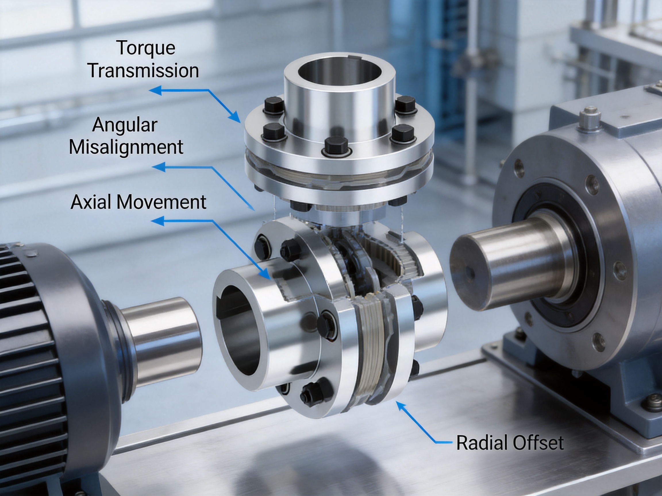
Three types of displacement are particularly important:
Angular displacement occurs when the two shafts are not perfectly parallel and their centerlines form a small angle. The diaphragm flexes to accommodate this angle.
Axial displacement occurs when the shaft ends move closer together or farther apart because of thermal expansion, bearing movement, installation tolerance, or operating conditions. The diaphragm group can compensate for this movement within the specified limit.
Radial displacement occurs when the two shaft centerlines are offset from one another. The coupling design allows limited radial compensation through the combined deformation of the diaphragm assembly.
Although a diaphragm coupling can compensate for these errors, it should not be used to correct poor alignment. Proper shaft alignment remains essential. Misalignment should be controlled during installation so that the coupling operates within its rated displacement limits. Correct alignment reduces diaphragm stress, bearing loads, vibration, and energy loss.
2. Working Principle of the Diaphragm Assembly
The diaphragm group is the core elastic element of the MP series. Multiple stainless steel sheets are assembled into a carefully controlled flexible pack. The sheets work together to transmit torque while allowing bending in the directions required for alignment compensation.
When torque is applied, the diaphragms carry the transmitted load between the input and output flanges. The coupling is designed to maintain a high torsional stiffness, which means that the angular twist between the driving and driven sides remains small under normal load. This characteristic is valuable in systems that require accurate speed transmission, controlled positioning, or stable phase relationships.
When an angular, axial, or radial offset exists, the diaphragm group experiences elastic bending. Because the element is metallic and operates without frictional sliding, there is no routine rubbing interface that requires grease or oil. If the coupling is correctly selected and the displacement limits are respected, the diaphragms can provide long service life.
The use of multiple diaphragm layers also helps distribute stress. Instead of concentrating the entire load in one thin sheet, the load is shared by the complete assembly. The number, thickness, shape, material, and fastening arrangement of the diaphragm layers are selected according to the coupling size, torque, speed, and required flexibility.
The coupling flanges and fasteners are equally important. The diaphragm cannot perform reliably if the flange faces are inaccurate or if the bolts are not tightened according to the specified procedure. For this reason, manufacturing accuracy, material control, machining quality, and assembly inspection are central to the performance of the finished coupling.
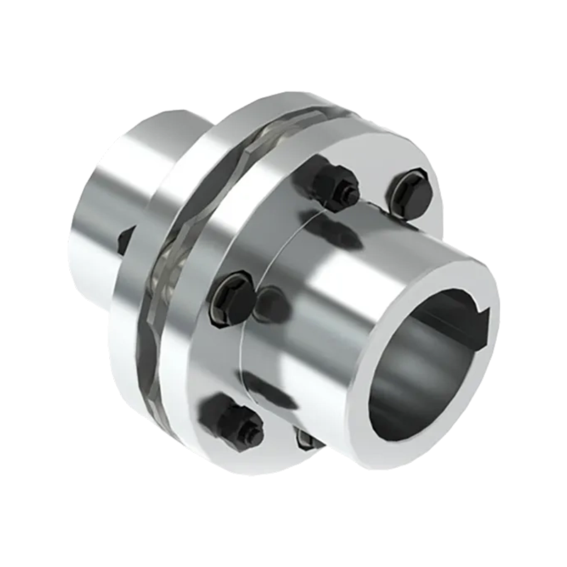
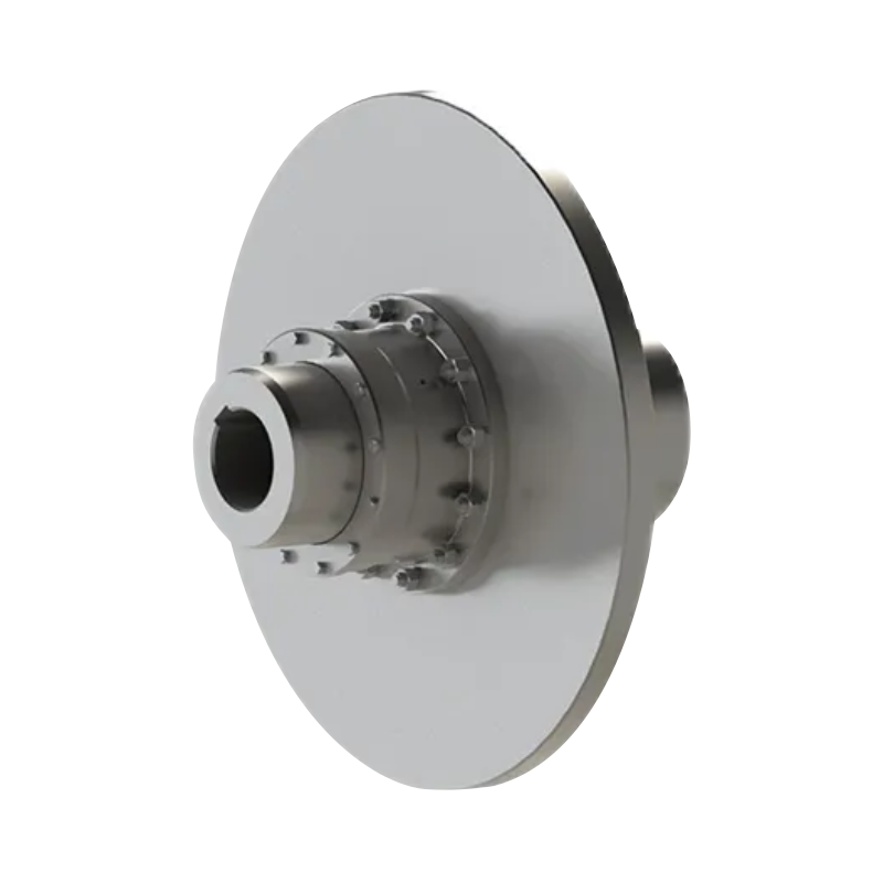
MP diaphragm coupling(Q/YP 21001X-2018)
3. Main Advantages of the MP Diaphragm Coupling
3.1 High Torsional Rigidity
One of the most important advantages of a diaphragm coupling is its high torsional rigidity. The metal diaphragm transmits torque with limited elastic twist, making the coupling suitable for machinery that requires accurate and stable rotational transmission.
High torsional rigidity is useful in high-speed motors, turbine-driven equipment, pumps, compressors, test stands, generators, and precision production lines. It helps reduce torsional oscillation and improves the coordination between the driver and the driven machine. In applications with frequent changes in load, a rigid torque path can also improve control response.
The MP specification table provides torsional stiffness values for different sizes. These values vary according to the coupling model and are expressed in millions of N·m per radian. The selected coupling must be checked against the actual operating torque, peak torque, starting torque, torsional vibration characteristics, and required safety factor.
3.2 Compensation for Multiple Types of Misalignment
The MP coupling can compensate for angular, axial, and radial shaft displacement. This is a major advantage in industrial equipment because perfect alignment cannot always be maintained during assembly or operation. Thermal expansion, foundation movement, bearing clearance, pipe loads, and machining tolerance can all produce small changes in shaft position.
Compensation capability protects connected equipment from excessive reaction forces. A coupling that cannot accommodate displacement may transfer alignment errors directly to motor bearings, pump bearings, gearboxes, or driven-machine shafts. By allowing controlled diaphragm flexure, the MP design reduces these unwanted loads.
Compensation should always be considered in combination. Angular, axial, and radial displacement may occur at the same time. A coupling operating near its maximum limit in one direction may have less available capacity in another direction. During selection, the user should provide all expected displacement values rather than evaluating only one type of misalignment.
3.3 Lubrication-Free Operation
The MP diaphragm coupling does not depend on grease or oil for its basic operating function. This eliminates routine lubrication work and avoids the contamination risks associated with lubricated gear couplings and other friction-based coupling designs.
Lubrication-free operation is particularly useful in equipment where maintenance access is restricted, where oil contamination is unacceptable, or where the coupling is installed in an environment that makes regular servicing difficult. It can also simplify plant maintenance schedules and reduce the number of consumable materials required during the equipment life cycle.
Although the diaphragm itself does not require lubrication, the entire installation should still be protected from unnecessary mechanical damage, chemical attack, and foreign-object interference. Fasteners, hubs, shaft fits, and guards must be inspected according to the equipment maintenance program.
3.4 Wide Temperature Capability
The MP diaphragm coupling is designed for operating temperatures from approximately -40 °C to +250 °C, subject to material selection, installation conditions, and the detailed engineering specification. This range allows the coupling to operate in many cold, hot, and fluctuating industrial environments.
Unlike elastomeric couplings, a metal diaphragm does not rely on the flexibility of a polymer element that may harden, soften, crack, or age rapidly when exposed to temperature extremes. This makes the diaphragm design attractive for high-temperature process equipment and outdoor installations in cold climates.
Temperature affects shafts, hubs, bearings, and connected machines as well as the coupling. Thermal growth calculations should therefore be completed for the entire drive train. The coupling’s axial compensation capability can help accommodate thermal movement, but the predicted movement must remain within the specified operating limit.
3.5 Corrosion and Harsh-Environment Suitability
The diaphragm group uses high-strength stainless steel sheets, which provide useful resistance to many corrosive environments. The exact corrosion performance depends on the selected material grade, surface treatment, chemical concentration, humidity, temperature, and exposure time.
The coupling may be used in metallurgy, chemical processing, marine systems, power equipment, water treatment, and other locations where moisture or corrosive media are present. For especially aggressive environments, the complete coupling should be reviewed rather than evaluating only the diaphragm material. Flanges, bolts, hubs, keyways, coatings, and protective guards must all be compatible with the surrounding conditions.
3.6 High-Speed Performance and Balance
The MP diaphragm coupling has a relatively simple rotating structure and can be dynamically balanced for high-speed operation. Its balanced construction helps reduce centrifugal-force-related vibration and supports stable operation at elevated rotational speed.
The allowable speed varies by model. The listed standard sizes range from approximately 10,700 r/min for MP1 to approximately 1,050 r/min for MP30. Smaller couplings generally have higher allowable speeds, while larger couplings are designed for substantially greater torque and mass.
Speed selection must consider more than the nominal rotational speed. The user should evaluate overspeed conditions, balance grade, shaft runout, installation accuracy, operating temperature, critical speed, and the effect of attached components. For high-speed systems, dynamic balancing and alignment verification are essential.
3.7 Compact and Relatively Simple Construction
Compared with many gear couplings, the MP diaphragm coupling has a comparatively simple structure. It does not require internal gear teeth, sliding sleeves, or a large quantity of grease. The reduction in internal moving interfaces can simplify inspection and help reduce maintenance requirements.
The simple structure also makes the coupling suitable for equipment with restricted installation space. Depending on the selected arrangement, the coupling can be removed through the flange and fastener system without moving the connected machine axially. This feature can reduce downtime during maintenance and make replacement work more convenient.
3.8 High Transmission Efficiency
Because the MP coupling transmits torque through a direct metallic load path and does not use an elastomer to absorb significant torsional deformation, it can achieve high transmission efficiency. The absence of routine sliding friction also limits mechanical losses associated with frictional contact.
High transmission efficiency is valuable in systems that operate continuously or consume substantial power. Even a small improvement in mechanical efficiency can produce meaningful energy savings over long operating periods. The actual efficiency of the complete drive system still depends on bearings, seals, gearboxes, alignment, motor performance, and operating load.
4. Comparison with Other Coupling Technologies
4.1 Comparison with Snake Spring Couplings
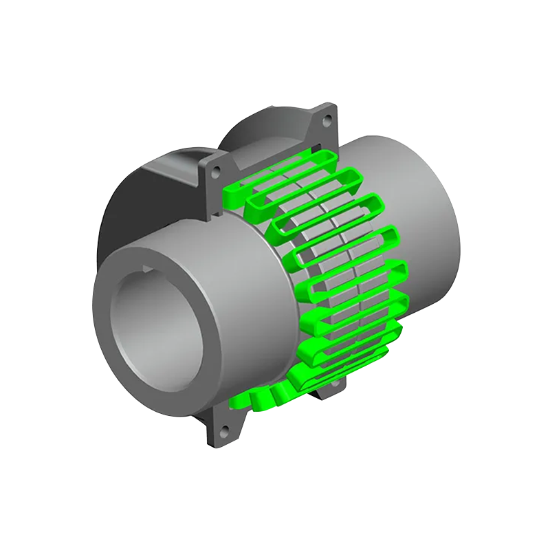
Snake spring couplings use a serpentine spring element installed between the teeth of two hubs. They are known for their ability to absorb shock loads and damp vibration. This makes them effective in certain heavy-duty applications with strong impact loading, frequent starts, or fluctuating torque.
The MP diaphragm coupling follows a different design philosophy. It prioritizes high torsional rigidity, high-speed balance, precise torque transmission, and compensation of shaft displacement through metallic diaphragm flexure. Its structure is generally simpler and produces less vibration and operating noise than a snake spring coupling in applications where the spring element’s damping capability is not required.
A snake spring coupling may be preferred when impact absorption and torsional damping are the dominant requirements. An MP diaphragm coupling may be preferred when accurate torque transmission, high speed, low maintenance, and high environmental resistance are more important. The correct choice depends on the actual load spectrum rather than on nominal torque alone.
The MP design also offers maintenance convenience. Its flange-and-fastener connection can permit disassembly without generating axial movement of the connected equipment, depending on the installation arrangement. This can be an important advantage when the motor, pump, gearbox, or generator is difficult to reposition.
4.2 Comparison with Gear Couplings
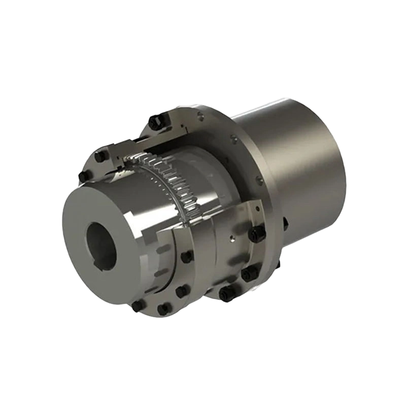
Gear couplings can transmit high torque and accommodate certain shaft movements through crowned gear teeth. However, they normally require lubrication, sealing, and regular inspection of the tooth surfaces and grease condition. Improper lubrication can lead to accelerated wear, tooth damage, overheating, and eventual failure.
The MP diaphragm coupling avoids these gear-tooth interfaces. Its lubrication-free operation can simplify maintenance and reduce the risk of grease leakage. It also provides high torsional stiffness and excellent suitability for high-speed applications when properly balanced.
Gear couplings may still be advantageous where very high torque density, substantial bore capacity, or particular axial and radial movement requirements are needed. The diaphragm coupling is often a strong alternative where cleanliness, speed, low maintenance, and precise transmission are priorities.
4.3 Comparison with Elastomeric Couplings
Elastomeric couplings use rubber, polyurethane, or other polymeric elements. Their main strengths include vibration damping, shock absorption, and relatively simple installation. They are often suitable for moderate-speed machinery and systems in which torsional flexibility is desirable.
However, elastomers can be affected by temperature, oil, chemicals, ultraviolet exposure, compression set, aging, and fatigue. Their torsional stiffness may also change during service. The MP diaphragm coupling offers more stable metallic performance across a wider temperature range and does not rely on an elastomeric insert that must be replaced as it ages.
An elastomeric coupling may be the better choice when vibration isolation is the primary objective. The MP coupling is generally more appropriate when high torsional rigidity, environmental stability, and long-term dimensional consistency are required.
4.4 Comparison with Rigid Flange Couplings
Rigid flange couplings provide a direct and highly rigid connection, but they cannot compensate for shaft misalignment. Even a small angular, radial, or axial error can impose significant loads on connected bearings and shafts.
The MP diaphragm coupling maintains much of the torsional rigidity associated with a rigid connection while providing controlled flexibility for alignment compensation. This makes it more forgiving in practical industrial installations. It should not be treated as a substitute for alignment, but it can help protect the drive train from normal operating displacement.
5. MP Series Product Range and Technical Parameters
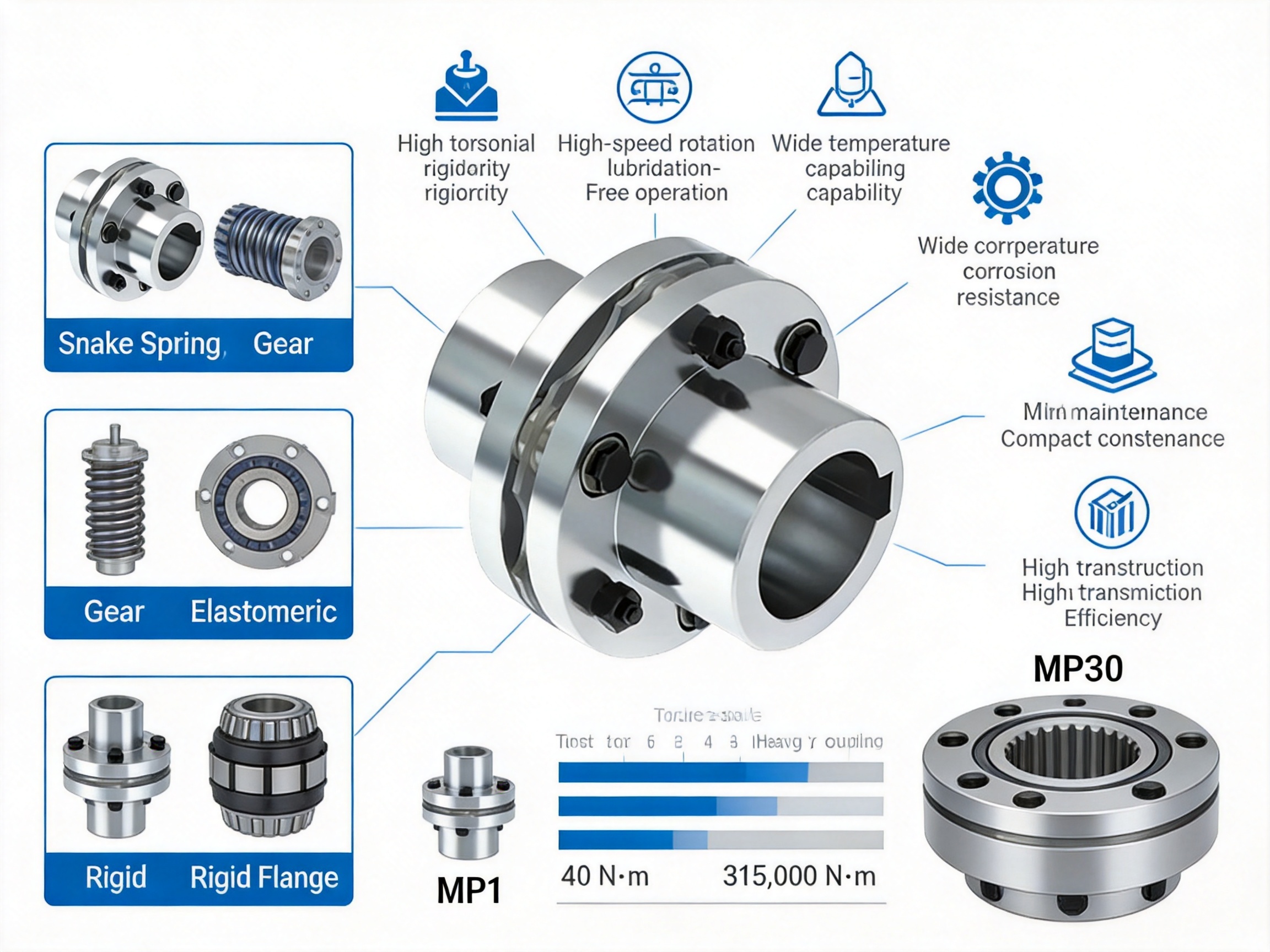
The MP series covers a broad range of torque and speed requirements. The standard specification table identifies models MP1 through MP30. Each model is associated with a nominal torque, allowable rotational speed, shaft bore combinations, shaft-hole lengths, outside diameters, flange dimensions, torsional stiffness, mass, and moment of inertia.
The smallest listed model, MP1, has a nominal torque of 40 N·m and an allowable speed of approximately 10,700 r/min. It accommodates shaft bores beginning at 14 mm, with additional bore combinations available in the size range. This model is suitable for compact, high-speed drive systems where low mass and low inertia are important.
MP2 and MP3 provide nominal torque ratings of 63 N·m and 100 N·m, with allowable speeds of approximately 9,300 r/min and 8,400 r/min. These sizes extend the range for compact motors, pumps, instruments, and other rotating equipment.
MP4 through MP7 cover nominal torque ratings from 250 N·m to 1,000 N·m. Their allowable speeds range from approximately 6,700 r/min to 4,750 r/min. These models provide a practical transition between small precision drives and more demanding industrial applications.
MP8 through MP13 cover nominal torque ratings from 1,600 N·m to 6,300 N·m. Their allowable speeds range from approximately 4,300 r/min to 3,200 r/min. These sizes can be considered for pumps, compressors, fans, generators, machine tools, and process equipment requiring increased torque capacity.
MP14 through MP18 extend the nominal torque range from 12,500 N·m to 31,500 N·m. Allowable speed decreases as size increases, from approximately 2,850 r/min for MP14 to approximately 2,150 r/min for MP18. These couplings are intended for heavier industrial drive trains with larger shaft diameters.
MP19 through MP24 provide nominal torque ratings from 40,000 N·m to 80,000 N·m. The listed allowable speeds range from approximately 1,950 r/min to 1,450 r/min. Shaft bores extend into larger diameters, and the coupling mass and moment of inertia increase accordingly.
MP25 through MP30 are the largest standard models in the supplied table. Their nominal torque ratings range from 100,000 N·m to 315,000 N·m, with allowable speeds from approximately 1,400 r/min to 1,050 r/min. These models are designed for large power transmission equipment, including heavy industrial machinery and high-capacity process systems.
| Model range | Nominal torque range | Approximate allowable speed range | Typical engineering role |
| MP1–MP3 | 40–100 N·m | 8,400–10,700 r/min | Compact, high-speed drives |
| MP4–MP7 | 250–1,000 N·m | 4,750–6,700 r/min | Medium-duty rotating equipment |
| MP8–MP13 | 1,600–6,300 N·m | 3,200–4,300 r/min | Industrial pumps, compressors, generators, and process machinery |
| MP14–MP18 | 12,500–31,500 N·m | 2,150–2,850 r/min | Heavy industrial drive systems |
| MP19–MP24 | 40,000–80,000 N·m | 1,450–1,950 r/min | Large power transmission equipment |
| MP25–MP30 | 100,000–315,000 N·m | 1,050–1,400 r/min | High-capacity heavy-duty machinery |
The table is intended for preliminary selection. Final selection must confirm the actual shaft bores, keyway or shrink-disc arrangement, allowable displacement, operating torque, peak torque, starting conditions, service factor, environmental conditions, balance requirements, and installation dimensions.
6. How to Select the Correct MP Coupling
6.1 Determine the Design Torque
The first step is to calculate the design torque rather than selecting a coupling from the motor’s nominal power alone. A typical calculation may use power and speed as follows:
Torque in N·m = 9550 × power in kW ÷ speed in r/min.
The calculated nominal torque should then be multiplied by an appropriate service factor. The service factor accounts for starting frequency, load fluctuation, impact, reversing operation, braking, duty cycle, and the characteristics of the driving and driven machines.
For systems with severe cyclic loading, the selection should also consider peak torque and fatigue. A coupling that is adequate for steady torque may not be adequate for repeated torsional shocks or resonance conditions.
6.2 Check Speed and Balance
The selected MP model must have an allowable speed higher than the maximum continuous operating speed and any foreseeable overspeed condition. The coupling’s balance condition should match the speed and sensitivity of the equipment.
High-speed systems require accurate shaft machining, concentric fits, controlled runout, and careful assembly. The coupling should be installed with its balance orientation preserved if balance marks or matched components are provided.
6.3 Confirm Shaft Bores and Connection Details
The standard table lists multiple shaft bore combinations for many MP models. The correct size must accommodate both connected shafts without exceeding the permitted bore diameter. Shaft-hole length, keyway dimensions, interference fits, clamping arrangements, and hub length should all be checked.
A coupling with sufficient torque capacity may still be unsuitable if the required shaft diameter exceeds its bore capacity or if the available installation length is insufficient. Custom hubs or modified flange configurations can be considered when standard dimensions do not match the machine design.
6.4 Evaluate Misalignment
Measure or calculate angular, radial, and axial displacement during installation and operation. Include thermal growth, bearing movement, foundation deflection, and expected process loads. The combined displacement must remain within the coupling’s allowable limits.
Alignment should be completed using suitable methods such as laser alignment, dial indicators, or precision measurement equipment. Flexible coupling capability should be used as a safeguard, not as permission to install shafts with excessive error.
6.5 Consider Temperature and Chemical Exposure
Provide the operating temperature range, ambient conditions, process-fluid exposure, humidity, dust, and cleaning chemicals when requesting a coupling. These factors affect the diaphragm material, fasteners, flange treatment, coatings, and protective arrangements.
For marine, chemical, or high-humidity installations, corrosion protection should be specified for the complete assembly. If the coupling is installed inside a housing, the housing material and ventilation should also be considered.
6.6 Check Torsional Vibration
High torsional rigidity is beneficial, but every drive system has its own torsional natural frequencies. Motor inertia, driven-machine inertia, shaft stiffness, gearbox characteristics, control equipment, and coupling stiffness interact with one another.
For critical applications, a torsional vibration analysis should be completed. The analysis can identify resonance risks, transient torque amplification, and the most suitable coupling stiffness. This is particularly important for reciprocating compressors, large fans, generators, marine propulsion systems, and systems with variable-frequency drives.
7. Manufacturing Quality and Engineering Strengths
The performance of a diaphragm coupling depends strongly on manufacturing accuracy. A flexible element may be designed correctly yet fail to achieve its expected life if the diaphragm material, flange geometry, bolt fit, surface finish, or assembly quality is inconsistent.
Zhongye Heavy Industry Technology combines research and development with production and sales. This integrated structure allows engineering feedback from industrial applications to be incorporated into product design and manufacturing. The company provides standard coupling models as well as customized non-standard solutions.
7.1 Material Control
The diaphragm group is manufactured from high-strength stainless steel sheet selected for fatigue resistance, elastic performance, and environmental suitability. Material control should include chemical composition verification, mechanical-property confirmation, thickness inspection, and traceability of production batches.
Material stability is especially important because the diaphragm operates under repeated cyclic deformation. Even when the displacement is small, millions of operating cycles can produce fatigue if stress concentration, surface damage, incorrect heat treatment, or material inconsistency is present.
7.2 Precision Machining
Coupling hubs and flanges require accurate machining of outside diameters, bores, bolt circles, flange faces, shoulders, and locating surfaces. Concentricity and perpendicularity influence balance, alignment, and the uniform distribution of diaphragm loading.
The company’s manufacturing facilities include a heavy workshop, precision workshop, warehouse, office facilities, and supporting infrastructure. The stated workshop arrangement includes approximately 5,500 square meters of heavy manufacturing space and approximately 4,600 square meters of precision manufacturing space. This combination supports both large industrial components and smaller precision coupling parts.
7.3 Controlled Assembly
Assembly of a diaphragm coupling requires more than simply tightening bolts. Diaphragm packs must be positioned correctly, flange faces must be clean and properly seated, and fasteners must be tightened in the specified sequence and torque range.
Controlled assembly helps prevent uneven stress, local diaphragm distortion, bolt loosening, and premature fatigue. Where required, components can be inspected for runout and balance after assembly. Assembly records and inspection results contribute to product traceability and quality assurance.
7.4 Testing and Inspection
Quality control should cover dimensional inspection, material verification, fastener inspection, runout measurement, balance checks, and functional or load-related testing appropriate to the product size and application.
The company identifies advanced testing facilities, strict quality control, and production guarantees as important business strengths. Its management system and products are associated with international quality requirements, including ISO 9001 certification. These systems support consistent manufacturing, documented inspection, corrective action, and continuous improvement.
7.5 Standard and Customized Production
Standard MP models provide a practical starting point for most applications. However, industrial drive systems often include unusual shaft spacing, large bores, special materials, limited installation access, high-temperature housings, or special balance requirements.
Zhongye provides non-standard design and manufacturing support for such requirements. Customization may include hub dimensions, shaft-hole sizes, flange configurations, spacer lengths, materials, coatings, protective structures, and application-specific performance requirements. The final design should be confirmed through engineering review and technical drawings before production.
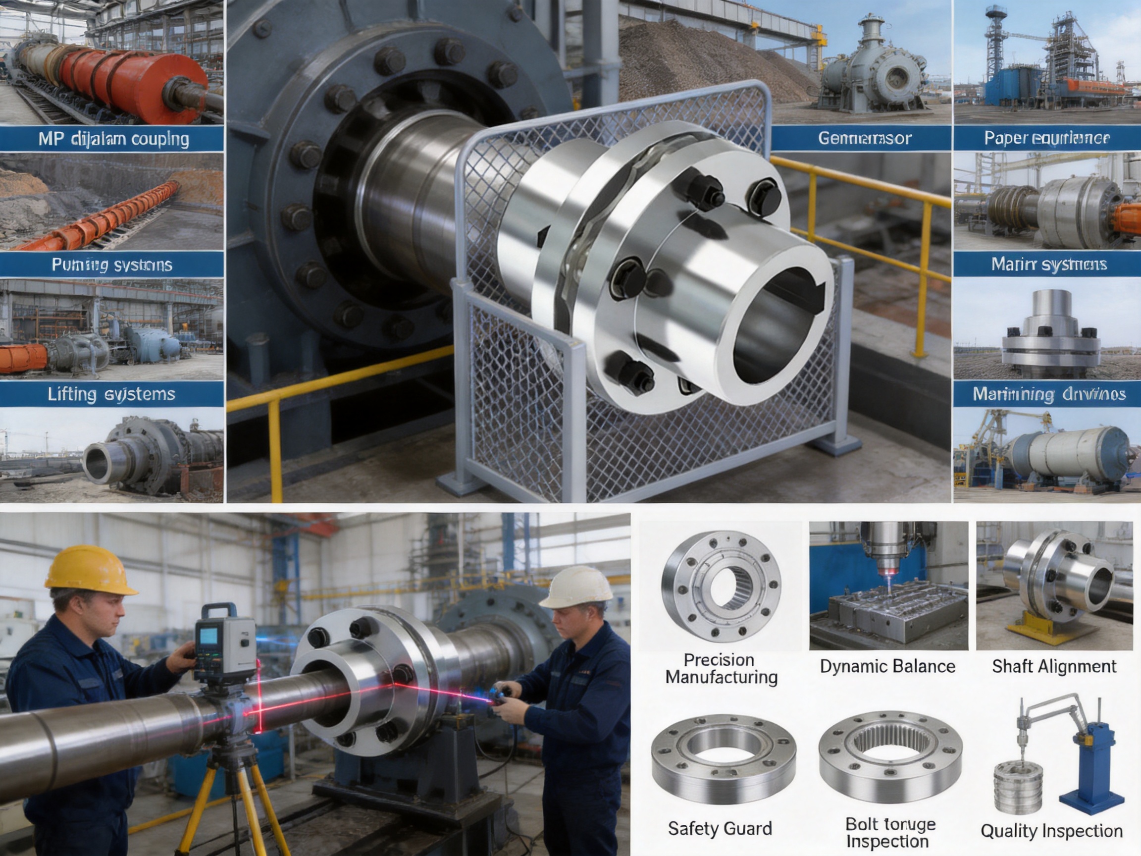
8. Industrial Applications
8.1 Metallurgical Equipment
Metallurgical machinery often combines high torque, shock loading, heat, dust, and demanding maintenance conditions. Rolling mills, conveyors, straightening machines, cooling systems, and auxiliary drives require couplings that can withstand repeated operation and alignment changes.
The MP diaphragm coupling is suitable where high torsional rigidity, low maintenance, and temperature resistance are important. Its compact structure can also help in machinery layouts where access is limited.
8.2 Mining Equipment
Mining equipment operates under dust, vibration, impact loads, and variable production conditions. Crushers, screens, pumps, conveyors, hoists, and processing machinery all depend on reliable torque transmission.
For applications with severe impact, a complete load analysis is required to determine whether diaphragm flexibility or a damping coupling is more appropriate. Where the torque is relatively controlled and accurate, low-maintenance transmission is important, and speed is significant, an MP coupling can be an effective solution.
8.3 Power and Generator Systems
Generators, exciters, pumps, fans, and auxiliary power equipment require stable shaft transmission and careful control of vibration. Diaphragm couplings are often considered for these applications because of their high torsional stiffness, balance capability, and absence of lubrication requirements.
Power-generation applications typically require detailed review of overspeed, short-circuit torque, torsional vibration, thermal movement, and emergency operating conditions. The coupling should be selected as part of the complete rotating-system analysis.
8.4 Chemical and Process Equipment
Chemical equipment may be exposed to corrosive media, high temperature, cleaning agents, or hazardous-area requirements. A lubrication-free coupling can reduce the risk of grease contamination and simplify maintenance.
Material compatibility must be verified carefully. Stainless steel diaphragm material is advantageous in many environments, but the exact chemical conditions should be submitted for review. Special coatings, fasteners, seals, guards, or material grades may be required.
8.5 Pumps and Water Equipment
Pumps and water-treatment equipment can experience pipe strain, thermal changes, moisture, and long operating hours. A flexible coupling can compensate for controlled shaft displacement and reduce the transfer of alignment forces into the pump and motor bearings.
Before installation, pipework should be independently supported and aligned. A coupling should not be used to absorb excessive nozzle loads or compensate for incorrectly installed piping.
8.6 Paper Machinery
Paper machines include numerous high-speed shafts, rolls, pumps, fans, and process drives. Smooth operation, low vibration, low maintenance, and accurate speed transmission are important for product quality and production continuity.
The MP coupling’s balance characteristics and metal diaphragm design make it suitable for selected paper-machine drives. Shaft alignment and torsional vibration analysis remain essential because paper machinery may contain long shafts and multiple connected rotating masses.
8.7 Port, Lifting, and Marine Equipment
Port cranes, lifting systems, winches, marine pumps, and shipboard auxiliary equipment may operate under variable loads, harsh weather, humidity, and restricted maintenance access. A coupling that does not require routine lubrication can reduce service work in difficult locations.
For lifting machinery, braking torque, emergency stopping, load holding, and shock loading must be evaluated. For marine applications, corrosion protection, classification requirements, installation space, and vibration conditions should be confirmed before selection.
9. Installation Recommendations
Before installing the MP diaphragm coupling, inspect all components for transport damage, corrosion, burrs, contamination, or deformation. Confirm that the model, bore dimensions, keyways, fasteners, and installation drawings correspond to the equipment requirements.
Clean the shaft surfaces and coupling bores. Remove burrs without reducing the required fit accuracy. Check the shaft diameter, shaft extension, key fit, shoulder position, and available axial space. The coupling should be installed according to the supplied technical drawing and assembly instructions.
Align the shafts before final tightening. Angular and parallel alignment should be measured using suitable precision instruments. If the equipment has thermal growth, align it according to the calculated cold-alignment offset rather than using a zero-offset assumption.
Install the coupling without forcing the hubs into position with impacts or excessive external loads. Do not use the diaphragm pack as a lifting point. Avoid bending, twisting, or prying against the metal elastic elements.
Tighten the fasteners in the specified sequence and to the specified torque. Uneven tightening can produce flange distortion and unequal diaphragm stress. If locking devices, fitted bolts, or special fasteners are provided, use them exactly as specified.
After installation, rotate the shaft manually where possible and confirm that there is no interference. Verify guard clearance, shaft-end clearance, bolt projection, and the absence of abnormal contact. A trial run should begin at low speed, followed by checks for vibration, noise, temperature, and fastener security.
10. Maintenance and Inspection
One advantage of the MP diaphragm coupling is its low routine maintenance requirement. Nevertheless, periodic inspection remains necessary because the coupling is a safety-critical rotating component.
Inspect the diaphragm packs for cracks, deformation, corrosion, fretting marks, looseness, or unusual discoloration. Cracks near bolt holes or flexible transitions are particularly important and should be investigated immediately.
Check flange bolts and fasteners for looseness, damaged threads, corrosion, or evidence of movement. Do not reuse damaged fasteners. If a bolt has been specified as a special fitted or high-strength component, replacement should use an equivalent approved part.
Monitor operating vibration and temperature. A sudden change may indicate shaft misalignment, bearing deterioration, unbalanced components, loose fasteners, excessive torque, or diaphragm damage. Vibration trending is useful because gradual changes can often be detected before a serious failure occurs.
Inspect the connected machinery as well as the coupling. Bearing wear, foundation settlement, pipe strain, shaft bending, and gearbox problems can change the alignment and impose loads on the diaphragm group.
If a diaphragm is damaged, replacement should normally be performed using an approved diaphragm assembly or repair kit. Individual sheets should not be substituted without engineering confirmation, because the number, thickness, material, and assembly arrangement influence the coupling’s stiffness and fatigue performance.
11. Safety Considerations
The coupling must always be enclosed by a suitable guard during operation. Rotating flanges, bolts, hubs, and diaphragms can cause severe injury if they are exposed. The guard should provide adequate clearance, ventilation, inspection access, and protection from accidental contact.
Never inspect, adjust, or lubricate nearby equipment while the coupling is rotating. Shut down and isolate the drive, disconnect stored energy, and follow the plant’s lockout and tagout procedures before removing the guard or performing maintenance.
Do not exceed the rated torque, speed, temperature, displacement, or bore limits. Short-duration overloads, emergency stops, reversing cycles, and starting transients must be included in the engineering evaluation.
If the coupling operates in a hazardous area, confirm the requirements for temperature classification, static electricity, guarding, grounding, material compatibility, and certification. Product suitability should be verified for the complete installation, not inferred only from the coupling’s general description.
12. Why Choose Zhongye Heavy Industry Technology?
Zhongye Heavy Industry Technology (Zhenjiang) Co., Ltd. is located in Zhenjiang, Jiangsu Province, China, and specializes in the research, manufacture, and sale of industrial couplings. Its product portfolio includes diaphragm couplings, gear couplings, elastic sleeve pin couplings, elastic pin couplings, universal couplings, tire couplings, jaw couplings, star couplings, drum couplings, grid couplings, flange couplings, safety couplings, roller-chain couplings, and other transmission products.
The company serves a wide range of industries, including metallurgical equipment, mining equipment, water equipment, lifting equipment, paper equipment, port equipment, and related industrial applications. This broad application base gives the engineering team experience with different load patterns, shaft arrangements, operating environments, and maintenance requirements.
Its facilities include heavy manufacturing space, precision workshops, offices, warehouses, and supporting infrastructure. The stated new workshop covers approximately 16,463.52 square meters, including dedicated heavy and precision production areas. This arrangement supports the manufacturing of both standard-size couplings and large custom transmission components.
The company’s stated strengths include strong research and development, manufacturing capability, testing facilities, strict quality control, complete product specifications, customization support, technical assistance before sale, non-standard design, and after-sales service. These capabilities are important for customers who require more than an off-the-shelf component.
For a customized MP diaphragm coupling, the engineering review can consider the motor power, operating speed, shaft diameters, shaft spacing, alignment conditions, temperature, corrosion exposure, installation access, balance requirements, torsional vibration, and applicable industry standards. This allows the coupling to be designed as part of the machine rather than treated as an isolated catalog item.
Customers can contact the company for technical consultation, product selection, dimensional confirmation, customization, quotation, and application support. The supplied contact information includes telephone support, email communication, and a dedicated messaging contact for international customers.
13. Frequently Asked Questions
Q1: What type of coupling is the MP diaphragm coupling?
The MP diaphragm coupling is a flexible coupling with metal elastic elements. Its primary flexible component is a multilayer stainless steel diaphragm group that transmits torque while compensating for controlled angular, axial, and radial shaft displacement.
Q2: Does the MP diaphragm coupling require lubrication?
No routine lubrication is required for the diaphragm transmission element. This is one of its main advantages over many gear couplings. However, the complete assembly should still be protected from contamination, corrosion, and mechanical damage, and all maintenance instructions should be followed.
Q3: Can it replace a snake spring coupling?
It can be considered as an alternative when high torsional rigidity, high-speed operation, precise torque transmission, low noise, and low maintenance are more important than maximum shock absorption. A snake spring coupling may remain preferable for applications dominated by severe impact and torsional damping requirements. The final choice should be based on a detailed load analysis.
Q4: Can it replace a gear coupling?
In many high-speed and lubrication-sensitive applications, the MP diaphragm coupling can provide an attractive alternative to a gear coupling. It offers high torsional rigidity, alignment compensation, and lubrication-free operation. However, bore capacity, displacement limits, torque peaks, speed, and installation dimensions must be checked before replacement.
Q5: What is the temperature range of the MP coupling?
The stated operating range is approximately -40 °C to +250 °C. Actual suitability depends on the coupling material configuration, fasteners, coatings, surrounding chemicals, thermal expansion, and application conditions. Special environments should be reviewed with the manufacturer.
Q6: What torque range is available?
The supplied standard table lists models MP1 through MP30 with nominal torque ratings from 40 N·m to 315,000 N·m. The product description identifies a broader family range extending from 0.063 to 10,000 kN·m according to the applicable design and configuration. Customers should confirm the required torque and model range during technical selection.
Q7: What information is needed for selection?
Important information includes motor or engine power, normal and maximum speed, nominal and peak torque, starting and braking conditions, shaft diameters, shaft lengths, keyway details, shaft spacing, angular and radial alignment, axial movement, ambient temperature, corrosive exposure, installation space, balance requirements, and the relevant industry or safety standards.
Q8: Is the coupling suitable for high-speed machinery?
Yes, the MP diaphragm coupling is designed for high-speed suitability, and the smaller models have allowable speeds above 10,000 r/min. High-speed use requires appropriate dynamic balance, accurate shaft alignment, correct fitting, controlled runout, and confirmation that the operating speed remains below the approved limit.
Q9: Can the MP coupling be customized?
Yes. Customized shaft bores, hub dimensions, flange arrangements, spacer lengths, materials, coatings, and other non-standard features can be considered. Customization should be confirmed through engineering drawings and a technical review before manufacturing.
Q10: How often should the coupling be inspected?
Inspection frequency depends on the operating speed, load severity, duty cycle, environment, safety requirements, and equipment maintenance policy. Visual inspection, vibration monitoring, fastener checks, and alignment verification should be included in the maintenance program. Immediate inspection is required after overload, abnormal vibration, collision, or unexpected shutdown.
Q11: Can the coupling compensate for poor alignment?
No. The coupling compensates for limited operating displacement, but it should not be used to correct poor installation. Excessive misalignment increases diaphragm stress and may reduce service life or damage connected bearings.
Q12: Is the MP diaphragm coupling suitable for corrosive environments?
It can be suitable for many corrosive or humid environments because the diaphragm group uses high-strength stainless steel. The complete coupling must be evaluated, including hubs, flanges, bolts, coatings, seals, and guards. The chemical concentration, temperature, and exposure duration should be provided for material confirmation.
14. Conclusion
The MP diaphragm coupling is a high-performance metal elastic element coupling for industrial systems that require accurate, reliable, and efficient torque transmission. Its multilayer stainless steel diaphragm assembly compensates for controlled angular, axial, and radial displacement while maintaining high torsional rigidity. The design operates without routine lubrication, supports high-speed applications, tolerates a broad temperature range, and provides a practical alternative to snake spring, gear, elastomeric, and rigid flange couplings in suitable applications.
The product range extends from compact MP1 models to large MP30 units, with standard nominal torque ratings from 40 N·m to 315,000 N·m in the supplied specifications. Multiple bore sizes and dimensional configurations allow the series to serve both precision drives and heavy industrial machinery. For unusual requirements, customized designs can be developed according to the equipment’s torque, speed, displacement, environmental, and installation conditions.
Zhongye Heavy Industry Technology supports the MP series with research and development, precision and heavy manufacturing facilities, testing capability, quality control, standard products, and non-standard engineering services. Its experience across metallurgy, mining, water equipment, lifting, paper, port, chemical, power, and other industries provides a strong foundation for application-specific coupling selection.
When properly selected, aligned, installed, guarded, and maintained, the MP diaphragm coupling can contribute to lower maintenance demand, reduced vibration and noise, improved transmission efficiency, and greater stability in demanding power transmission systems.
References
Q/YP 21001X-2018, MP Diaphragm Coupling Product Standard.
Manufacturer-supplied MP diaphragm coupling technical parameter table and dimensional data.
ISO 9001, Quality Management Systems — Requirements.
General engineering principles for flexible shaft coupling selection, alignment, torsional vibration, and rotating equipment maintenance.
Manufacturer technical information concerning diaphragm couplings, industrial coupling applications, customization, inspection, and after-sales engineering support.
Product: MP diaphragm coupling(Q/YP 21001X-2018)

- Quick Links
- About
- Products
- Our Service
- News & Events
- Contact
- Products Series
- Flexible Couplings with Non-Elastic Elements
- Flexible Couplings with Metal Elastic Elements
- Flexible Couplings with Non-Metallic Elastic Elements
- Safety Coupling
- Rigid Coupling
- Contact Us
- Tel : +86 511 8572 3800 +86 511 8572 3900
- Mobile : +86 15106109009
- Email : sales@couplingzy.com
- Add:No.1 Zhongye Yingbin Avenue, Gaozi Street, Dantu Economic Development Zone, Zhenjiang City, Jiangsu Province, China.


