:+86 15106109009
:sales@couplingzy.com


 English
  русский
  Español
  عربى
عربى  Português
  Deutsch
  Türk
Türk  Indonesia

ZCD Type Conical Shaft Hole Elastic Pin Gear Coupling: Design, Performance, Selection, and Manufacturing Quality
Content
- 1 Product Principle and Structural Configuration
- 2 Main Performance Advantages
- 3 Operating Conditions and Limitations
- 4 Technical Parameters and Size Range
- 5 How the Coupling Compares with Alternative Designs
- 6 Manufacturing Strengths and Quality Assurance
- 7 Application Areas
- 8 Coupling Selection Procedure
- 9 Installation and Maintenance Recommendations
- 10 Customized Coupling Solutions
- 11 Why Manufacturing Capability Matters to Buyers
- 12 Application Checklist for Engineers
- 13 Q&A
- 13.1 What is the primary purpose of the ZCD conical shaft hole?
- 13.2 How does the coupling compensate for misalignment?
- 13.3 Does the coupling require grease or oil?
- 13.4 What happens if the machine is overloaded?
- 13.5 What is the temperature range of the standard design?
- 13.6 Is the ZCD coupling suitable for high-speed machinery?
- 13.7 How does it compare with a rigid coupling?
- 13.8 How does it compare with a lubricated gear coupling?
- 13.9 Can the coupling be customized?
- 13.10 What information is needed to select a model?
- 13.11 What should be checked after installation?
- 14 Conclusion
- 15 References
- 16 Product: ZCD type conical shaft hole elastic pin gear coupling(Q/YZ33007X-2018)-副本
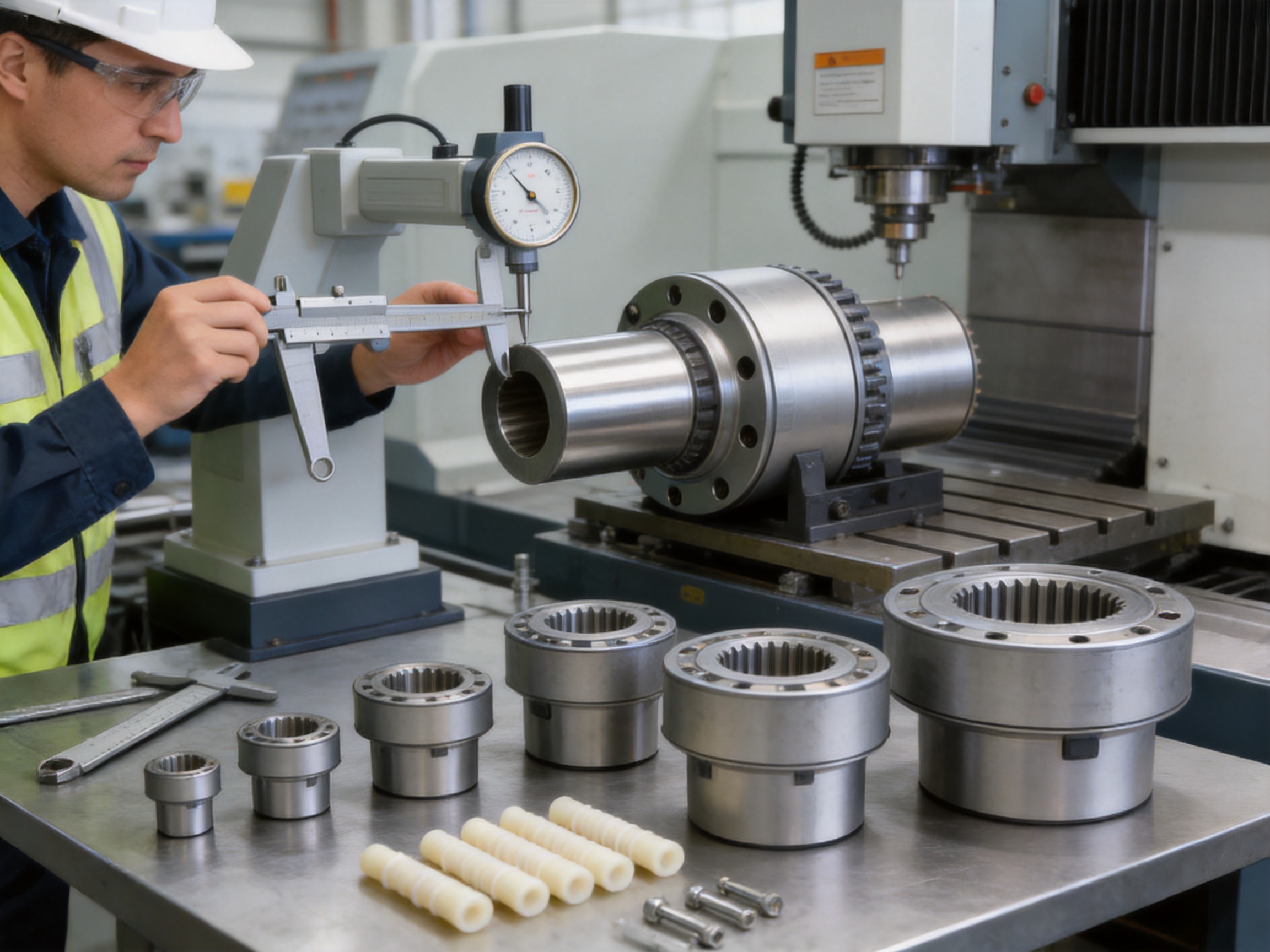
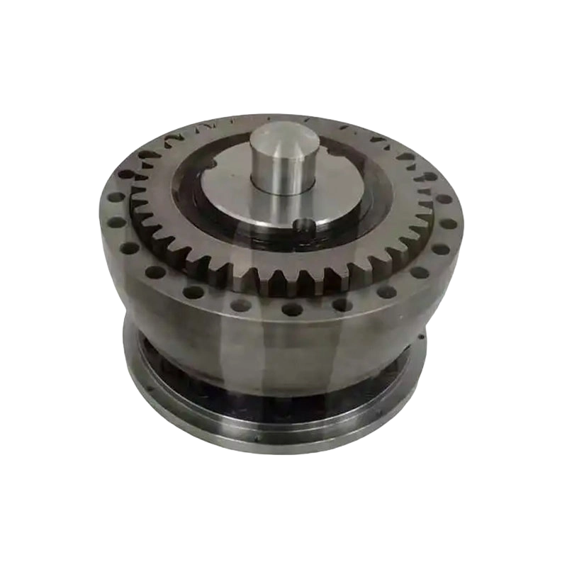
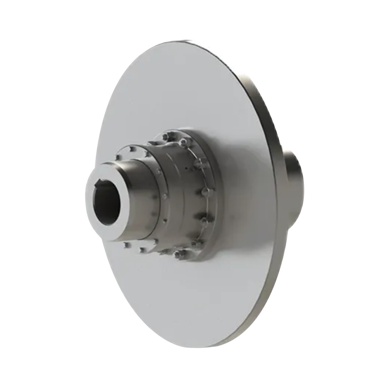
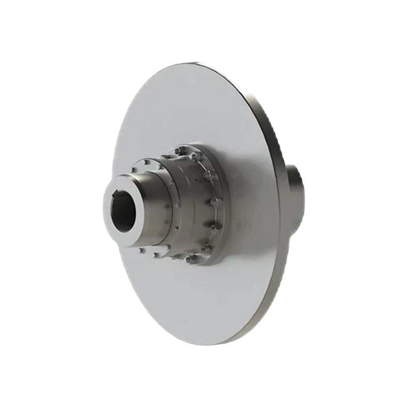
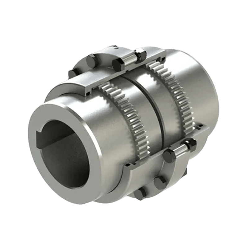
The ZCD type conical shaft hole elastic pin gear coupling is a heavy-duty flexible coupling designed for reliable torque transmission between rotating shafts. It combines the load-carrying characteristics of a gear coupling with the flexibility, overload protection, and comparatively simple maintenance of an elastic pin coupling. Its conical shaft hole arrangement gives the coupling an additional practical advantage: it can be fitted directly to a conical motor, gearbox, or reducer output shaft with accurate centering and convenient assembly.
For industrial machinery, coupling selection affects much more than the connection between two shafts. The coupling influences alignment tolerance, vibration behavior, bearing loads, maintenance intervals, installation time, operational safety, and the service life of motors, reducers, pumps, rolls, conveyors, and other connected equipment. A coupling that is too rigid can transfer misalignment loads into the bearings and shafts. A coupling that is too flexible or incorrectly selected may suffer excessive deformation, heat generation, or premature pin failure. The ZCD design addresses these requirements through a balanced combination of structural strength, elastic compensation, conical shaft fit, and overload response.
This product is suitable for medium- and heavy-duty machinery in metallurgical equipment, mining equipment, water equipment, lifting machinery, paper-making equipment, port machinery, and other industrial applications. Its nominal torque range extends from 112 N·m to 100,000 N·m, while the available sizes cover a broad range of shaft diameters and operating speeds. The result is a versatile coupling family that can serve both compact drive systems and large industrial transmission lines.
Product Principle and Structural Configuration
A ZCD coupling consists principally of two coupling halves, shaft connection sections, elastic pins, pin holes or tooth-groove contact areas, and protective components. One end incorporates a conical shaft hole. When the corresponding conical shaft is inserted and tightened, the mating taper produces a close and centered fit. The other shaft connection can be configured according to the application and required bore dimensions.
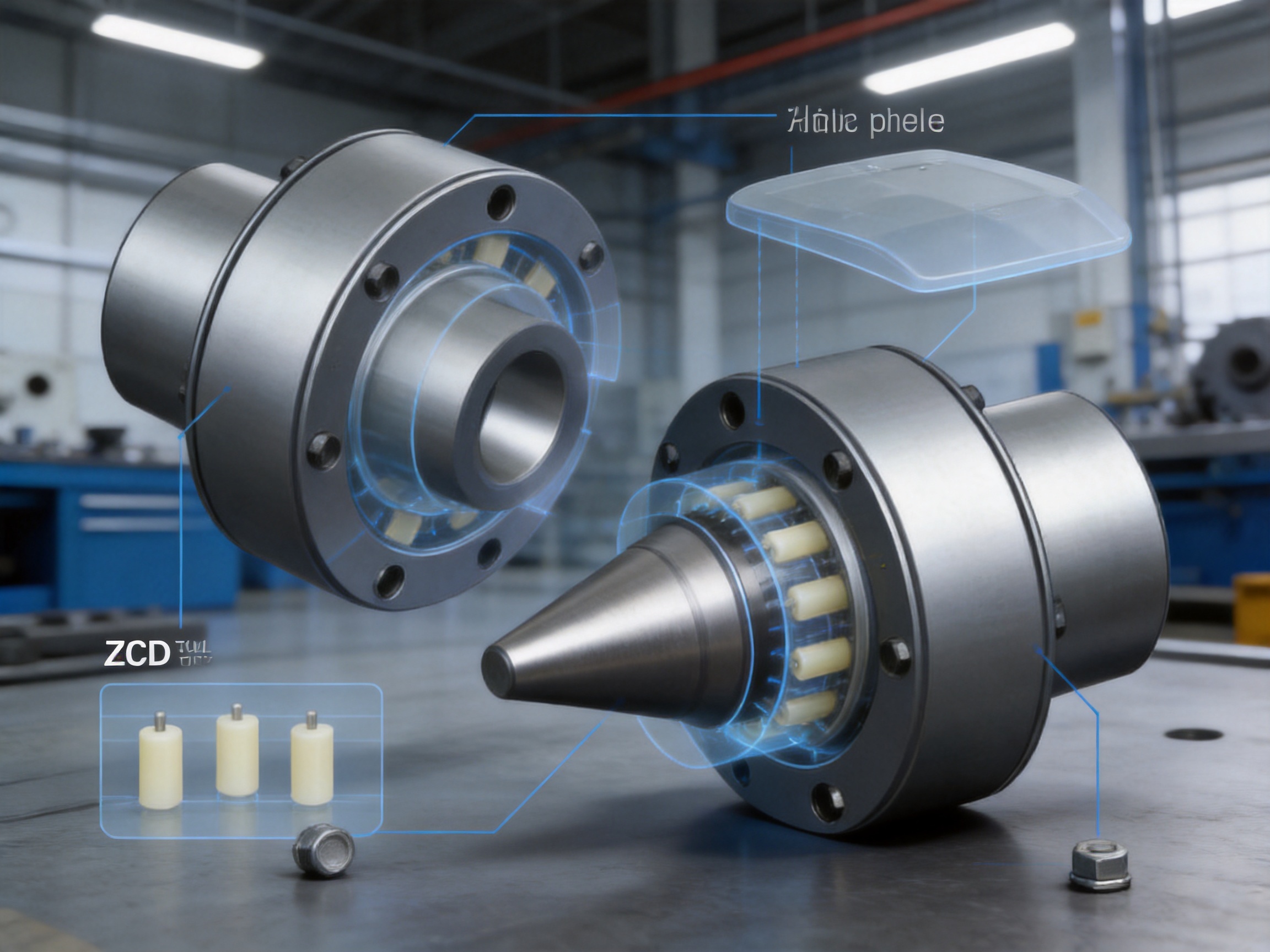
The elastic pins are the working flexible elements. They transmit torque between the coupling halves while allowing limited relative movement caused by installation errors, shaft deflection, thermal expansion, and deformation under load. In normal operation, the pins share the transmitted force across multiple contact points. When an abnormal overload occurs, the pins can deform or break before more expensive components such as the motor shaft, reducer gearing, or driven-machine shaft are seriously damaged.
The gear-like arrangement of the coupling does not mean that the product requires the same precision gear manufacturing or continuous lubrication as a conventional toothed coupling. Instead, the elastic pin and tooth-groove arrangement provides a practical compromise between compact torque transmission and flexible compensation. This helps the coupling achieve a smaller turning diameter and lower mass than some traditional gear coupling solutions with a similar nominal torque rating.
The conical shaft hole is an important part of the design. Cylindrical bore couplings commonly require a key, interference fit, clamping arrangement, or additional locking assembly. A conical connection can improve concentricity during installation and reduce the risk of eccentric mounting when the mating shaft is manufactured to the specified taper. It also facilitates removal when maintenance or replacement is required. Correct tightening, surface cleanliness, and compliance with the specified taper are essential for achieving the intended performance.
Main Performance Advantages
Accurate Conical Shaft Fit
The tapered connection automatically guides the coupling into a centered position as it is installed. This can reduce radial runout and help establish a more accurate shaft-to-coupling relationship than a loosely fitted cylindrical bore. The result is particularly valuable for motors and gear reducers that use conical output shafts, because the coupling can be matched directly to the shaft geometry rather than relying on an additional adapter.
A close conical fit also distributes contact pressure over the mating taper. When properly tightened, the connection can transmit torque securely while maintaining good concentricity. This minimizes the possibility of fretting, local contact stress, or uneven loading caused by an incorrectly centered coupling. For maintenance teams, the ability to install and remove the coupling without complex gear disassembly can reduce downtime.
High Torque Capacity in a Compact Form
The ZCD series provides a wide nominal torque range. The smallest listed model, ZCD1, has a nominal torque of 112 N·m. The largest listed model, ZCD13, reaches 100,000 N·m. Between these limits are multiple sizes for 250 N·m, 630 N·m, 1,800 N·m, 4,500 N·m, 8,000 N·m, 11,200 N·m, 18,000 N·m, 25,000 N·m, 31,500 N·m, 40,000 N·m, and 63,000 N·m.
This range allows engineers to select a coupling closer to the actual operating requirement instead of using an oversized unit simply because intermediate sizes are unavailable. Proper sizing can reduce unnecessary rotating mass and help control the load imposed on shafts and bearings. In applications where space is limited, the relatively compact structure and reduced turning diameter can be advantageous compared with bulkier coupling arrangements.
Under the same nominal torque, the design may provide a smaller volume and lower weight than some traditional toothed coupling alternatives. This does not mean that every ZCD coupling will be lighter than every competing design; the final comparison depends on torque, speed, bore, service factor, guard requirements, and application-specific design. However, its efficient force path and limited number of components make it an attractive alternative where compactness and high torque transmission are important.
Three-Directional Compensation
Industrial shafts are rarely aligned perfectly under all operating conditions. Installation tolerances, foundation settlement, shaft bending, thermal expansion, bearing clearance, and casing deformation can create axial, radial, and angular misalignment. The ZCD elastic pin gear coupling is designed to accommodate these three forms of deviation within specified limits.
The approximate axial compensation capability is 1.5 to 2.5 millimeters, depending on the size and working condition. Approximate radial compensation is about 0.3 to 0.6 millimeters, and angular compensation is about 0.5 degrees. These figures are design references rather than permission to operate continuously at the maximum value. The actual allowable misalignment should be checked against the relevant technical documentation, speed, torque, load fluctuation, and service factor.
Axial flexibility can accommodate shaft movement caused by thermal growth or changes in the position of connected equipment. Radial flexibility helps prevent moderate installation errors from becoming excessive bearing loads. Angular flexibility assists in situations where two shafts are not perfectly collinear. By reducing the transmission of alignment error into connected machinery, the coupling can support longer bearing and shaft life.
Low Maintenance and No Routine Lubrication
The nylon elastic pins are self-lubricating in normal service and do not require the routine grease replenishment associated with many gear couplings. Eliminating regular lubrication simplifies maintenance planning, reduces the possibility of lubricant leakage, and keeps the surrounding equipment cleaner. This is particularly beneficial near paper machinery, water equipment, food-adjacent production areas, and locations where oil or grease contamination is undesirable.
The structure contains relatively few parts and does not depend on high-precision gear tooth processing. If the elastic pins eventually wear or are damaged by overload, they can generally be replaced after removing the protective plate and following the prescribed maintenance procedure. A pin replacement operation is usually simpler than replacing a complete coupling or dismantling a lubricated gear coupling.
Although the coupling is described as maintenance-friendly, it should not be treated as maintenance-free under all conditions. Operators should inspect the pins, pin holes, protective plate, fasteners, shaft connection, and signs of overheating or abnormal wear at suitable intervals. Inspection frequency should increase in applications with frequent starts and stops, impact loads, reversing, severe vibration, or frequent overload events.
Overload Protection
One of the practical advantages of an elastic pin coupling is its ability to provide a sacrificial overload function. If the transmitted torque rises beyond the safe operating level, the nylon pins can deform or break. This interrupts or reduces torque transmission and can protect more expensive drive components. The coupling therefore acts as a simple mechanical weak link in the transmission system.
Overload protection must be considered during system design. A broken pin is not a substitute for a properly selected safety coupling, torque limiter, brake, or control system when the application demands precise overload protection. However, it can reduce the severity of a sudden jam or abnormal torque spike. The replacement cause should always be investigated before new pins are installed, since repeated pin failure may indicate undersizing, excessive misalignment, insufficient tightening, shock loading, or a problem in the driven machine.
Operating Conditions and Limitations
The specified working temperature range for the ZCD type conical shaft hole elastic pin gear coupling is approximately -20°C to +70°C. This range suits many general industrial applications, including medium- and heavy-load machinery with frequent starting and stopping. The nylon pins and other non-metallic components should not be exposed to temperatures, chemicals, radiation, or environmental conditions beyond their material capability.
The coupling is not the first choice for applications requiring extremely low vibration or noise, very high rotational speed, or operation at extreme temperatures. Its vibration and noise reduction performance is considered average for this type of mechanical coupling. Where precision servo response, ultra-low torsional backlash, high-speed balancing, or strict acoustic requirements are dominant, a diaphragm coupling, bellows coupling, high-performance elastomer coupling, or specialized high-speed gear coupling may be more appropriate.
Engineers should also evaluate the influence of water, dust, corrosive chemicals, abrasive particles, and ultraviolet exposure. The protective plate can help shield the elastic pins from external contact, but the complete installation may require additional guarding or environmental protection. The coupling should never be operated without an appropriate guard where rotating parts could pose a safety hazard.
Speed is another important limitation. The allowable speed decreases as coupling size and mass increase. For example, the listed allowable speed is 5,000 r/min for ZCD1, 4,500 r/min for ZCD3, 4,200 r/min for ZCD4, 4,000 r/min for ZCD5, 3,300 r/min for ZCD6, 2,900 r/min for ZCD7, 2,500 r/min for ZCD8, 2,300 r/min for ZCD9, 2,100 r/min for ZCD10, 2,000 r/min for ZCD11, 1,700 r/min for ZCD12, and 1,500 r/min for ZCD13. The coupling must be selected so that the actual working speed remains within the allowable value after considering balance quality and operating conditions.
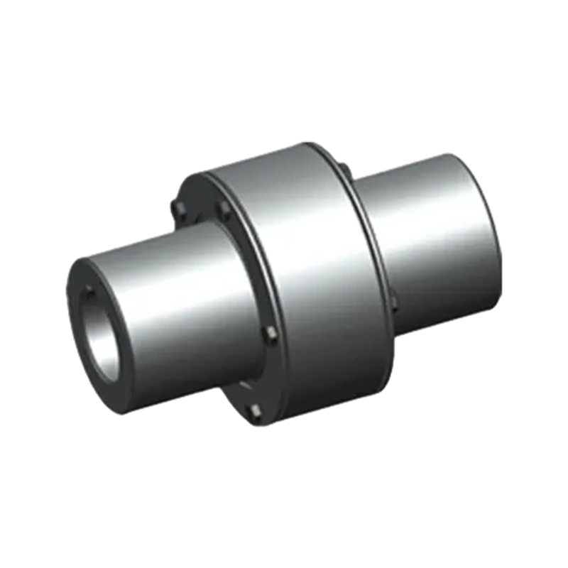
ZCD type conical shaft hole elastic pin gear coupling(Q/YZ33007X-2018)-副本
Technical Parameters and Size Range
The following table summarizes the principal data supplied for the ZCD series. Several sizes include more than one shaft-hole group. Within a group, the shaft-hole length and outside dimensions may vary according to the selected bore. Engineers should confirm the final dimensional drawing before releasing a purchase order or machining connected shafts.
| Model | Nominal Torque (N·m) | Allowable Speed (r/min) | Representative Shaft Hole Diameter (mm) | D (mm) | D1 (mm) | B (mm) | S (mm) | Mass Range (kg) |
|---|---|---|---|---|---|---|---|---|
| ZCD1 | 112 | 5000 | 6–28 | 78 | 40–44 | 65–75 | 14.5–20.5 | 2.08–2.30 |
| ZCD2 | 250 | Not separately stated | 25–32 | 90 | 50–60 | 88–92 | 20.5–24.5 | 3.74–3.98 |
| ZCD3 | 630 | 4500 | 30–42 | 118 | 60–84 | 115–125 | 25–31 | 9.43–10.30 |
| ZCD4 | 1800 | 4200 | 40–60 | 158 | 84–107 | 145–152 | 32–39 | 22.36–22.46 |
| ZCD5 | 4500 | 4000 | 50–80 | 192 | 84–132 | 145–158 | 32–44 | 21.71–30.45 |
| ZCD6 | 8000 | 3300 | 60–95 | 230 | 107–132 | 175–178 | 40–45 | 47.25–48.16 |
| ZCD7 | 11200 | 2900 | 70–110 | 260 | 107–167 | 178–188 | 40–50 | 64.13–69.42 |
| ZCD8 | 18000 | 2500 | 80–130 | 300 | 132–202 | 202–212 | 46–56 | 101.70–108.80 |
| ZCD9 | 25000 | 2300 | 90–150 | 335 | 132–202 | 232–242 | 47–57 | 142.40–157.50 |
| ZCD10 | 31500 | 2100 | 100–170 | 355 | 167–242 | 240–255 | 53–68 | 184.10–188.50 |
| ZCD11 | 40000 | 2000 | 110–180 | 380 | 167–242 | 260–275 | 53–68 | 212.30–225.00 |
| ZCD12 | 63000 | 1700 | 130–200 | 445 | 202–282 | 282–302 | 58–78 | 327.90–352.70 |
| ZCD13 | 100000 | 1500 | 150–220 | 515 | 202–282 | 313–332 | 58–78 | 468.40–524.50 |
The supplied dimensional data also includes moment of inertia values from approximately 0.002 kg·m² for the smaller ZCD1 configuration to approximately 16.514 kg·m² for the largest listed ZCD13 configuration. Moment of inertia is important for acceleration, deceleration, reversing, and servo-related calculations. A coupling with a higher moment of inertia requires more torque to accelerate at the same rate, so it should be included in the total rotating inertia calculation of the machine.
Mass varies with shaft-hole diameter and dimensional configuration. In some model groups, a larger bore does not simply produce a proportional change in mass because the shaft-hole length, hub geometry, and balance requirements may also change. The final selected configuration should therefore be evaluated using the exact drawing and data sheet rather than the nominal model name alone.
How the Coupling Compares with Alternative Designs
Comparison with Conventional Gear Couplings
Conventional gear couplings are well known for high torque density and their ability to accommodate misalignment. However, many gear couplings require lubrication to protect the gear teeth and seals. Lubricant maintenance can be inconvenient in dusty, wet, hot, or environmentally sensitive areas. Gear couplings may also involve more components, more demanding sealing requirements, and greater maintenance complexity.
The ZCD coupling offers a simpler non-metallic elastic element system. Its nylon pins are self-lubricating under normal conditions, and the coupling does not depend on continuous gear-tooth lubrication. Its limited number of parts can shorten inspection and replacement work. It can also provide overload protection through pin deformation or fracture, whereas a conventional gear coupling may transfer a severe overload directly into the connected machine unless another protection device is installed.
A gear coupling may still be preferable for a very high-temperature installation, highly demanding high-speed operation, or an application requiring a specific torsional stiffness and large misalignment capacity. The correct comparison must include the full operating environment rather than nominal torque alone. For general medium- and heavy-duty service within the specified temperature and speed limits, the ZCD configuration can offer a lower-maintenance and more cost-effective alternative.
Comparison with Rigid Flange Couplings
Rigid couplings provide a strong and direct shaft connection, but they require excellent alignment. Any angular, radial, or axial error is transferred to the shafts, bearings, and machine housings. In equipment exposed to foundation movement, thermal expansion, or repeated loading changes, this can result in elevated bearing temperature, shaft stress, and premature wear.
The ZCD coupling is more forgiving because its elastic pins accommodate limited three-directional misalignment. This flexibility makes it more suitable for general industrial installations where perfect alignment cannot be maintained throughout the operating cycle. A rigid coupling may be appropriate when the shafts are structurally integrated, alignment is permanently controlled, and no compensation is desired. It is less suitable when the connected machines have different support structures or significant operating deflection.
Comparison with Diaphragm and Disc Couplings
Diaphragm and disc couplings are often selected for high-speed machinery, precise torsional response, and applications that require metallic flexible elements. They can provide low backlash and good repeatability, but they may require more precise alignment, careful bolt installation, and strict control of axial movement. Their performance can also be sensitive to fretting, disc stress, and incorrect assembly.
The ZCD coupling uses a more straightforward elastic pin arrangement. This can make it easier to inspect and repair in heavy industrial environments. It is generally better suited to moderate speeds, frequent starts and stops, and applications where the primary goals are reliable torque transmission, practical misalignment compensation, and economical maintenance rather than extreme precision or maximum speed.
Comparison with Elastomeric Jaw or Tire Couplings
Jaw, tire, and other elastomeric couplings can provide effective vibration damping and compact installation. They may be advantageous when noise reduction, shock absorption, or a softer torsional characteristic is required. However, elastomeric components may be more sensitive to temperature, chemical exposure, aging, and compression set.
The ZCD elastic pin coupling offers a different balance. It provides useful flexibility and overload response while maintaining a strong torque transmission path. Its conical shaft hole is a specific advantage for compatible conical shafts, and its wide torque range makes it suitable for larger industrial drive systems than many small elastomeric jaw couplings. Where vibration isolation is the primary requirement, however, a coupling designed specifically for high damping may be a better choice.
Manufacturing Strengths and Quality Assurance
Zhongye Heavy Industry Technology (Zhenjiang) Co., Ltd. integrates coupling research and development, manufacturing, and sales. Its product range includes toothed couplings, elastic sleeve pin couplings, elastic pin couplings, gear couplings with elastic pins, universal couplings, tire couplings, jaw couplings, star couplings, diaphragm couplings, drum couplings, grid couplings, Oldham couplings, flange couplings, clip-shell couplings, roller-chain couplings, safety couplings, and customized non-standard couplings.
This broad product experience is valuable when manufacturing the ZCD series because coupling performance depends on more than the machining of a single hub. The design team must understand shaft loading, speed, alignment, torque fluctuation, materials, heat treatment, balancing, assembly, and field maintenance. Experience across many coupling families helps engineers choose a suitable structural solution when a customer’s operating conditions do not match a standard catalog configuration.
The company’s new workshop covers approximately 16,463.52 square meters. It includes a heavy workshop of approximately 5,500 square meters, a precision workshop of approximately 4,600 square meters, an office building and gymnasium of approximately 2,000 square meters, a dining hall, warehouse space, and supporting roads, landscaping, and parking areas. The separation of heavy and precision work areas supports the manufacture of both large torque-transmission components and smaller, dimensionally controlled coupling parts.
Engineering and Product Development
The manufacturing process begins with application analysis and product engineering. Important inputs include nominal torque, peak torque, motor power, speed, shaft diameters, shaft extensions, operating temperature, start-stop frequency, environmental conditions, misalignment, and required service life. For a customized coupling, the engineering team can review the available installation space, key or taper geometry, guard arrangement, balance grade, and connection details before preparing a design.
Computer-aided design and technical documentation help define the coupling geometry, tolerances, assembly sequence, and inspection points. For large or unusual drive systems, the design can be checked against calculated shaft loads and expected operating conditions. This engineering stage is particularly important for conical shaft holes, because taper angle, contact length, surface finish, axial positioning, and tightening method all affect the final fit.
Material Preparation and Machining
Coupling hubs and related metal components require suitable materials with adequate strength, toughness, machinability, and resistance to fatigue. Material selection depends on the coupling size, torque, speed, load cycle, environmental conditions, and customer requirements. Forged, rolled, or other qualified steel forms may be used according to the design and manufacturing route.
Heavy-duty machining requires stable equipment, suitable cutting parameters, controlled fixturing, and sufficient allowance for finishing operations. The bore, outer diameter, face surfaces, pin holes, and mounting features must be produced in a sequence that controls distortion and maintains coaxiality. Large components may require multiple setups, so reference surfaces and inspection procedures are essential for preventing cumulative error.
For a conical shaft hole, the taper must be machined and verified carefully. A surface that appears visually acceptable may still have excessive angle error, waviness, or insufficient contact area. Precision measurement of the taper and trial fitting with a calibrated reference can help confirm that the coupling will seat correctly on the mating shaft.
Heat Treatment and Surface Control
Where required by the design, heat treatment can improve the strength, hardness, wear resistance, and fatigue performance of metal coupling components. Heat-treatment procedures must be controlled to avoid excessive distortion or residual stress. After treatment, critical surfaces may require additional machining or grinding to achieve the final dimensional requirements.
Surface quality is relevant to both performance and service life. Correct surface finish on the conical bore supports uniform contact and reduces the possibility of localized stress. Properly finished pin holes support even load distribution around the elastic pins. Corrosion protection, painting, or other surface treatments may be specified according to the operating environment and customer requirements.
Assembly and Inspection
Assembly technicians must verify the orientation of hubs, the correct pin material and dimensions, the fit of protective components, and the tightening of fasteners. The pins should be installed without damage, excessive impact, or contamination. The protective plate must be secure and must not interfere with rotating components.
Quality control can include dimensional inspection, bore and taper verification, runout checks, visual examination, material verification, balance assessment, and functional assembly checks. For large couplings, inspection of concentricity and face runout is especially important because small errors can become significant at high torque or speed. The company identifies advanced testing facilities, strict quality control, complete specifications, and reliable production guarantees as key manufacturing strengths.
Quality management based on ISO 9001 principles provides a framework for controlled production, documentation, traceability, corrective action, and continuous improvement. Certification alone does not replace application-specific inspection, but a formal quality system helps ensure that engineering changes, raw materials, process instructions, and final inspections are managed consistently.
Application Areas
Metallurgical Machinery
Rolling mills, processing lines, conveyors, shears, and auxiliary metallurgical equipment often experience high starting torque, impact loads, and frequent cycling. A flexible coupling can help accommodate shaft alignment changes while transmitting substantial torque. The ZCD series is suitable where the speed and temperature remain within the specified range and where the elastic pin arrangement can be protected from excessive heat, scale, and contamination.
Mining and Bulk Material Equipment
Mining machinery may include crushers, feeders, screens, conveyors, pumps, and hoists. These systems can experience variable loads, shock events, and difficult maintenance access. The coupling’s simple structure and overload pin function can be useful in such environments. However, crusher and high-impact applications require careful service-factor selection, because repeated overloads may shorten pin life even when the nominal motor torque appears acceptable.
Water and Pumping Equipment
Water equipment, pumping stations, treatment systems, and industrial circulation systems commonly require reliable operation with limited lubrication work. The self-lubricating nylon pins can simplify routine maintenance. The environmental suitability of the complete coupling should still be confirmed, particularly if the equipment is exposed to chemicals, salt water, high humidity, or outdoor weather.
Lifting and Port Machinery
Cranes, winches, hoists, ship-loading systems, and port conveyors may require strong torque transmission and resistance to repeated starting and stopping. The overload response of the elastic pins can provide an additional protective feature. Lifting applications must comply with all applicable safety requirements, and the coupling should be integrated with the machine’s brake, overload limiter, emergency stop, and guarding systems.
Paper-Making Equipment
Paper machinery often benefits from clean operation and reduced lubricant use. The coupling can be applied to auxiliary drives, rollers, pumps, conveyors, and other systems where moderate flexibility and dependable transmission are needed. The final selection should account for operating speed, moisture, washdown procedures, temperature, and the need for precise synchronization.
Coupling Selection Procedure
Step One: Determine the Required Torque
Begin with the motor or prime-mover power and operating speed. The basic running torque can be estimated from the relationship between power, speed, and torque. The selected coupling should not be based only on the average running torque. Starting torque, braking torque, reversing torque, peak process torque, and transient impact loads must also be considered.
A service factor should be applied according to the driven machine. Smoothly loaded pumps may require a lower factor than crushers, conveyors with heavy starts, hoists, or reciprocating machinery. If the calculated design torque approaches the nominal rating, the next larger coupling size should generally be considered. The engineering review should also verify that the shaft diameter and available shaft length are compatible with the selected model.
Step Two: Check Speed and Inertia
The actual operating speed must be below the allowable speed for the selected coupling. The system should also be evaluated for acceleration and deceleration. Coupling mass and moment of inertia affect motor starting time, braking energy, and dynamic response. In reversing applications, the torsional and impact effects of direction changes may be more important than steady-state torque.
High-speed operation requires attention to balance, runout, guard clearance, and installation accuracy. Even if the nominal speed is below the catalog limit, substantial misalignment or eccentric mounting can increase vibration and dynamic forces. The coupling should therefore be installed concentrically and inspected after assembly.
Step Three: Verify Shaft Holes and Taper
Confirm both shaft-hole diameters, shaft-hole lengths, keyways or other locking details, and the conical shaft specification. The mating shaft must be manufactured to the correct taper and must be free of burrs, dents, rust, oil contamination, and other defects that could prevent full contact.
Do not force a coupling onto a shaft by striking the hub or using an uncontrolled impact method. Follow the specified installation procedure, use suitable tools, and apply the correct tightening force. A taper connection that is not fully seated may produce inaccurate alignment and unstable torque transmission.
Step Four: Evaluate Misalignment
Measure the initial radial, angular, and axial alignment of the connected machines. The coupling provides compensation, but it should not be used to compensate for poor installation. Excessive misalignment increases pin deflection, contact pressure, heat, and fatigue. It may also impose loads on the bearings and reduce the service life of the coupling.
After alignment, allow for expected thermal expansion and operating movement. The cold alignment target may differ from the running alignment target when a motor, reducer, pump, or other machine changes position as it reaches operating temperature.
Step Five: Confirm the Environment
Review the temperature range, moisture, chemicals, dust, ultraviolet exposure, washdown, and nearby heat sources. The standard nylon pin material is intended for the stated general operating range. If the coupling will be exposed to temperatures below -20°C or above +70°C, or to aggressive chemicals, a special material or alternative coupling design may be needed.
Installation and Maintenance Recommendations
Before installation, isolate all energy sources and follow the site’s lockout and safety procedures. Rotating machinery must be completely stopped, and the shafts must be secured against unexpected movement. Inspect the coupling for transport damage and verify that the model, bore dimensions, pins, fasteners, and protective plate match the order.
Clean the shaft and conical bore using an approved method. Remove burrs and check the taper contact. Do not apply unapproved lubricants or coatings to the mating surfaces because they may change the friction characteristics of the taper. Position the coupling according to the assembly drawing and tighten the connection in the specified sequence.
Align the connected shafts using appropriate dial indicators, laser alignment equipment, or other suitable instruments. Check angular and parallel offset. After tightening all connection hardware, repeat the alignment measurement because tightening can cause a small positional change. Rotate the assembly by hand, where safe and practical, to confirm that there is no interference or abnormal resistance.
Install the protective plate and any required machine guard before commissioning. During the initial run, monitor vibration, noise, bearing temperature, pin behavior, and coupling movement. Stop the machine if there is abnormal knocking, rapid heating, excessive vibration, or visible movement of the coupling halves.
Routine inspection should look for cracked, deformed, loose, or missing elastic pins. Examine the pin holes and adjacent metal surfaces for elongation, fretting, impact marks, or unusual wear. Check the conical connection for signs of movement and inspect fasteners for loosening. A clean protective plate makes it easier to detect dust or fragments from pin wear.
If a pin fails, identify the reason before replacing it. Possible causes include excessive torque, repeated shock loads, a jammed driven machine, incorrect pin material, shaft misalignment, loose fasteners, excessive temperature, chemical attack, or an incorrect coupling size. Replacing pins without correcting the underlying cause can lead to repeated failure and unplanned downtime.

Customized Coupling Solutions
Standard ZCD sizes cover a broad range, but many industrial installations have special shaft dimensions, unusual space limitations, particular taper requirements, or unique speed and load conditions. The manufacturer undertakes the design and manufacture of non-standard couplings to address such requirements.
A customized design may include modified shaft holes, special shaft-hole lengths, alternative keyways, different hub dimensions, adapted protective plates, special materials, corrosion-resistant finishes, balancing requirements, or dimensional changes for direct replacement of an existing coupling. Customization should begin with complete technical information rather than a nominal torque value alone.
Useful customer information includes motor power, operating speed, prime-mover type, driven-machine type, normal and peak torque, start-stop frequency, reversing frequency, shaft diameters, shaft lengths, taper details, key dimensions, available axial space, expected misalignment, ambient temperature, environmental contaminants, and required service life. Drawings, photographs, or the dimensions of the existing installation can further improve design accuracy.
The manufacturer’s R&D and production capabilities support a complete process from technical discussion to design, machining, assembly, inspection, and after-sales assistance. This is an advantage over suppliers that only provide catalog dimensions and cannot modify the coupling for a difficult installation. A custom solution should still be validated through engineering calculations and, where necessary, prototype or trial fitting.
Why Manufacturing Capability Matters to Buyers
Couplings are relatively compact components, but they are safety-critical links in many power-transmission systems. A dimensional error in a bore or taper can create installation problems. Poor concentricity can cause vibration. Incorrect pin material can reduce flexibility or overload life. Inconsistent heat treatment or insufficient inspection can affect fatigue strength. For this reason, a buyer should evaluate the supplier’s complete manufacturing capability rather than comparing price and nominal torque alone.
A manufacturer with heavy machining capacity can handle large coupling bodies and high-torque models without relying entirely on external processing. A precision workshop supports controlled production of bores, faces, pin holes, and mating features. Testing facilities provide a means of checking dimensions, runout, materials, and assembly quality. A documented quality system helps maintain consistency across repeated orders and replacement parts.
Technical support is another important purchasing factor. The correct coupling depends on the connected equipment and operating cycle. A supplier able to review application data can help avoid both undersizing and unnecessary oversizing. Pre-sale support can identify the appropriate model, shaft-hole configuration, service factor, and installation method. After-sale support can assist with replacement pins, troubleshooting, inspection, and future customization.
Zhongye Heavy Industry Technology is positioned as an integrated coupling manufacturer with strong R&D and manufacturing capabilities, complete specifications, customization support, quality control, testing resources, and service support. Its products are used across multiple industrial fields, including metallurgy, mining, water equipment, lifting, paper, and port machinery. This application breadth provides practical experience for both standard and non-standard transmission requirements.
Application Checklist for Engineers
Before specifying a ZCD coupling, confirm the following points:
1. The calculated design torque, including service factor and peak loads, is within the selected model’s nominal capacity.
2. The actual operating speed is below the allowable speed for the exact size and configuration.
3. Both shaft diameters and shaft lengths match the available bore and shaft-hole length.
4. The conical shaft and coupling bore have matching taper specifications and adequate contact length.
5. The initial and operating misalignment values are within the allowable axial, radial, and angular compensation ranges.
6. The working temperature remains between approximately -20°C and +70°C unless a special design has been approved.
7. The elastic pin material is compatible with the environment and expected load cycle.
8. The coupling’s mass and moment of inertia have been included in acceleration and braking calculations.
9. A suitable guard is provided to prevent contact with rotating components and to contain fragments in the event of pin failure.
10. The installation team has access to the assembly drawing, tightening instructions, alignment requirements, and replacement-parts information.
Q&A
What is the primary purpose of the ZCD conical shaft hole?
The conical shaft hole is designed to fit a compatible conical shaft, such as the output shaft of a motor or gear reducer. The taper helps guide the coupling into position, improves centering, and can simplify installation and removal. The shaft and coupling taper must match accurately, and the connection must be tightened according to the specified procedure.
How does the coupling compensate for misalignment?
The elastic pins and tooth-groove arrangement allow limited axial, radial, and angular movement between the coupling halves. Approximate reference values are 1.5 to 2.5 millimeters of axial compensation, 0.3 to 0.6 millimeters of radial compensation, and about 0.5 degrees of angular compensation. These values should not replace the exact product limits for the selected size.
Does the coupling require grease or oil?
The nylon elastic pins are self-lubricating under normal operating conditions, so routine lubrication is not normally required. This is one of the product’s maintenance advantages over many conventional gear couplings. The coupling should nevertheless be inspected regularly, and external environmental protection should be provided where water, chemicals, dust, or high temperature may affect the pins.
What happens if the machine is overloaded?
The elastic pins can deform or break when subjected to an excessive torque or shock load. This sacrificial behavior may protect the motor, reducer, shaft, or other expensive transmission components. Pin failure should always be investigated before replacement, because repeated failure may indicate improper sizing, excessive misalignment, jamming, or abnormal operating conditions.
What is the temperature range of the standard design?
The stated working temperature range is approximately -20°C to +70°C. Applications outside this range require a technical review. A different elastic element material or a different coupling design may be necessary for extreme temperatures, severe chemical exposure, or special environmental conditions.
Is the ZCD coupling suitable for high-speed machinery?
The coupling can be used in applications within the allowable speed of the selected model. The listed allowable speeds range from 5,000 r/min for the smallest model to 1,500 r/min for the largest model. It is not intended to be a universal solution for extreme high-speed equipment. Balance, runout, misalignment, guard clearance, and exact operating speed must all be checked.
How does it compare with a rigid coupling?
A rigid coupling requires very accurate alignment and transfers shaft movement directly into the connected machinery. The ZCD coupling provides limited three-directional compensation, making it more suitable where thermal movement, foundation changes, shaft deflection, or installation tolerances exist. A rigid coupling may still be appropriate when the shafts are permanently aligned and no flexibility is required.
How does it compare with a lubricated gear coupling?
The ZCD design has a simpler structure, uses self-lubricating nylon pins, and can provide overload protection through pin deformation or breakage. It may reduce routine maintenance and operating cost in general industrial service. A lubricated gear coupling may be preferable in certain high-temperature, high-speed, or specialized applications, so the comparison should include the complete duty cycle and environment.
Can the coupling be customized?
Yes. Non-standard coupling design and manufacture are available for special shaft dimensions, conical shaft requirements, space constraints, materials, protective components, and other application needs. Customers should provide complete technical information, including power, speed, torque, shaft dimensions, operating temperature, misalignment, and environmental conditions.
What information is needed to select a model?
The most useful information includes motor power, speed, shaft diameters, shaft lengths, shaft-hole and taper details, driven-machine type, normal and peak torque, start-stop frequency, reversing frequency, environmental temperature, misalignment, and available installation space. The supplier can use this information to select the model and confirm the exact dimensions.
What should be checked after installation?
Check the taper seating, fastener tightening, shaft alignment, pin installation, protective plate, guard clearance, and runout. During commissioning, monitor vibration, noise, temperature, and unusual coupling movement. A second alignment check after tightening is recommended because the position may change slightly during assembly.
Conclusion
The ZCD type conical shaft hole elastic pin gear coupling is a practical solution for medium- and heavy-duty shaft transmission. Its principal strengths are the accurate conical shaft fit, broad torque range, compact construction, three-directional compensation, self-lubricating elastic pins, straightforward maintenance, and useful overload response. These features make it a strong alternative to rigid couplings where misalignment exists and to conventional lubricated gear couplings where simple maintenance and lower operating complexity are priorities.
The product is not intended for every application. Extreme temperatures, severe chemical exposure, very high speed, strict vibration-control requirements, and precision servo duties may require a different coupling technology. Correct selection must consider torque, speed, inertia, shaft geometry, alignment, environmental conditions, and service factor. When these factors are properly evaluated, the ZCD series can provide stable torque transmission and dependable service in a wide variety of industrial machines.
Manufacturing quality is central to the performance of a conical shaft coupling. Controlled engineering, heavy and precision machining capability, taper inspection, dimensional control, assembly verification, testing facilities, quality management, and technical support all contribute to long-term reliability. Zhongye Heavy Industry Technology combines coupling design, manufacturing, sales, customization, and after-sales service, enabling customers to obtain both standard ZCD models and application-specific coupling solutions.
For buyers seeking a cost-effective connection for conical shaft extension systems, the ZCD coupling offers a balanced combination of load capacity, alignment tolerance, maintenance convenience, and production flexibility. With correct sizing, accurate installation, suitable guarding, and regular inspection, it can help protect connected machinery while supporting efficient and reliable industrial operation.
References
1. Product technical data for the ZCD type conical shaft hole elastic pin gear coupling, including nominal torque, allowable speed, shaft-hole dimensions, moment of inertia, and mass.
2. Q/YZ33007X-2018, technical reference identified for the ZCD type conical shaft hole elastic pin gear coupling.
3. ISO 9001, Quality management systems, principles for controlled manufacturing and continual improvement.
4. General engineering principles for flexible shaft couplings, shaft alignment, torque calculation, misalignment compensation, and rotating-equipment maintenance.
5. Manufacturer information concerning coupling research and development, manufacturing facilities, product applications, quality control, customization, and technical service.
Product: ZCD type conical shaft hole elastic pin gear coupling(Q/YZ33007X-2018)-副本
- Quick Links
- About
- Products
- Our Service
- News & Events
- Contact
- Products Series
- Flexible Couplings with Non-Elastic Elements
- Flexible Couplings with Metal Elastic Elements
- Flexible Couplings with Non-Metallic Elastic Elements
- Safety Coupling
- Rigid Coupling
- Contact Us
- Tel : +86 511 8572 3800 +86 511 8572 3900
- Mobile : +86 15106109009
- Email : sales@couplingzy.com
- Add:No.1 Zhongye Yingbin Avenue, Gaozi Street, Dantu Economic Development Zone, Zhenjiang City, Jiangsu Province, China.


