:+86 15106109009
:sales@couplingzy.com


 English
  русский
  Español
  عربى
عربى  Português
  Deutsch
  Türk
Türk  Indonesia

MCS Plum-Shaped Elastic Coupling: High-Reliability Flanged Power Transmission for Heavy Industry
Content
- 1 Product Overview and Operating Principle
- 2 Structural Features of the MCS Coupling
- 3 Performance Advantages
- 4 Technical Parameters and Size Range
- 5 Advantages Compared with Alternative Coupling Designs
- 6 Manufacturing Strengths and Quality Control
- 7 Application Areas
- 8 Installation Recommendations
- 9 Maintenance and Service Life
- 10 Engineering Support and Customization
- 11 Why the MCS Series Is a Practical Industrial Choice
- 12 Selection Checklist
- 13 Frequently Asked Questions
- 13.1 What type of coupling is the MCS product?
- 13.2 What standard does the MCS coupling comply with?
- 13.3 What is the torque range of the MCS series?
- 13.4 What is the maximum speed available?
- 13.5 What shaft hole sizes are available?
- 13.6 Does the coupling require lubrication?
- 13.7 Can the MCS coupling compensate for shaft misalignment?
- 13.8 Can it be used for reversing applications?
- 13.9 Does the elastic element provide electrical insulation?
- 13.10 What operating temperature range is specified?
- 13.11 What industries use the MCS coupling?
- 13.12 Can customized couplings be manufactured?
- 13.13 What information is required for product selection?
- 13.14 How should the elastic element be maintained?
- 13.15 Is a coupling guard necessary?
- 14 Conclusion
- 15 References
- 16 Product: MCS type plum shaped elastic coupling (Q/YM 35014X-2018)
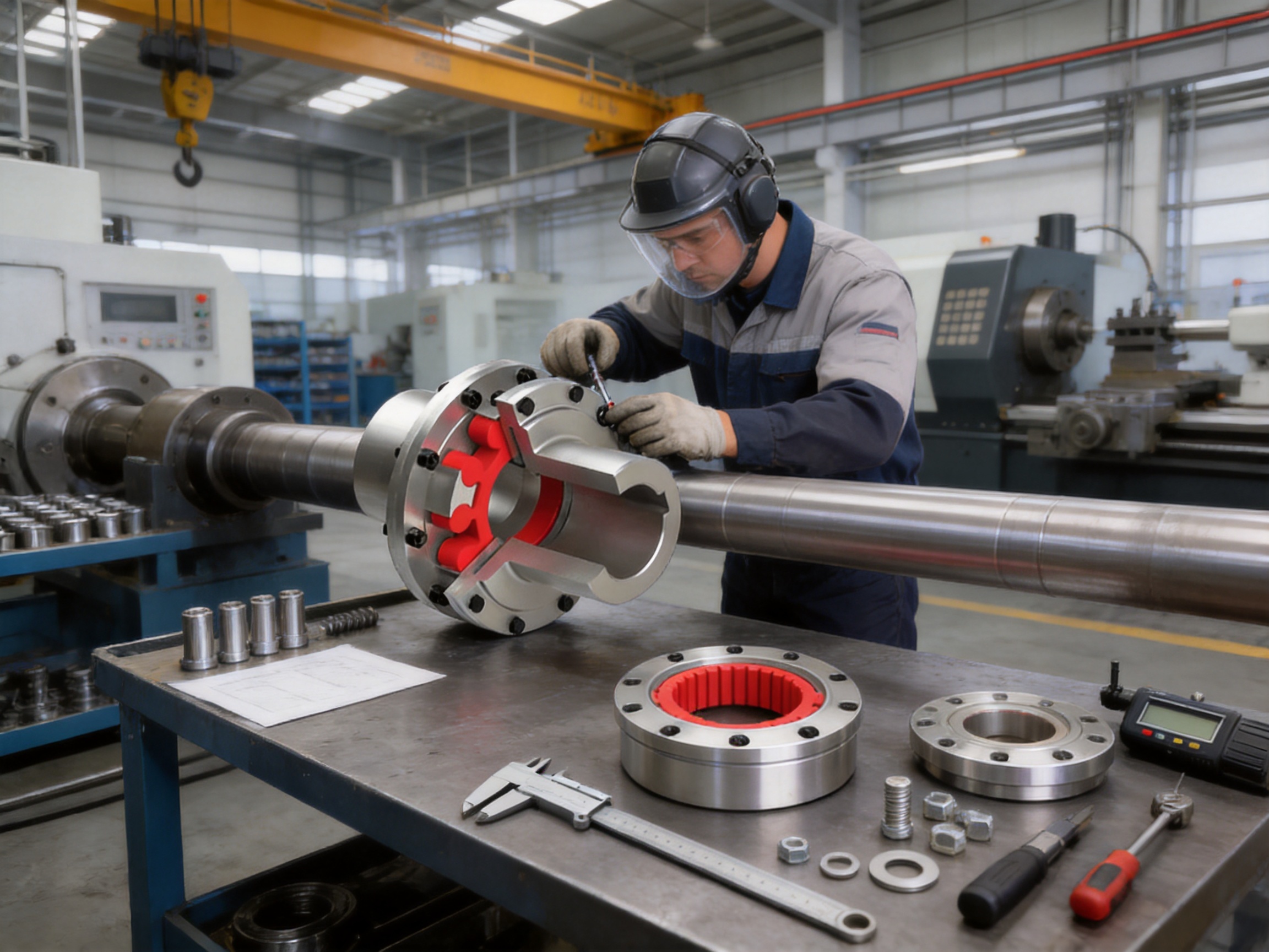
Modern industrial machinery depends on reliable torque transmission under conditions that are often demanding, variable, and unforgiving. Metallurgical lines, mining equipment, lifting systems, water machinery, paper production lines, and port equipment all require coupling components that can connect shafts securely while accommodating the small alignment errors, vibration, shock loads, and operating variations that occur in real installations. The MCS type plum-shaped elastic coupling is designed for this purpose. Manufactured in accordance with the Q/YM 35014X-2018 standard, it combines a double-flange structure with a non-metallic plum-shaped elastic element to create a compact, flexible, and service-friendly shaft connection.
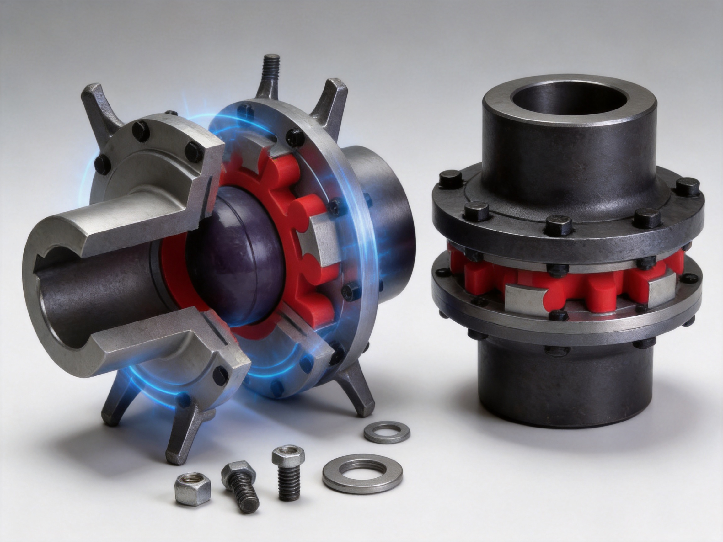
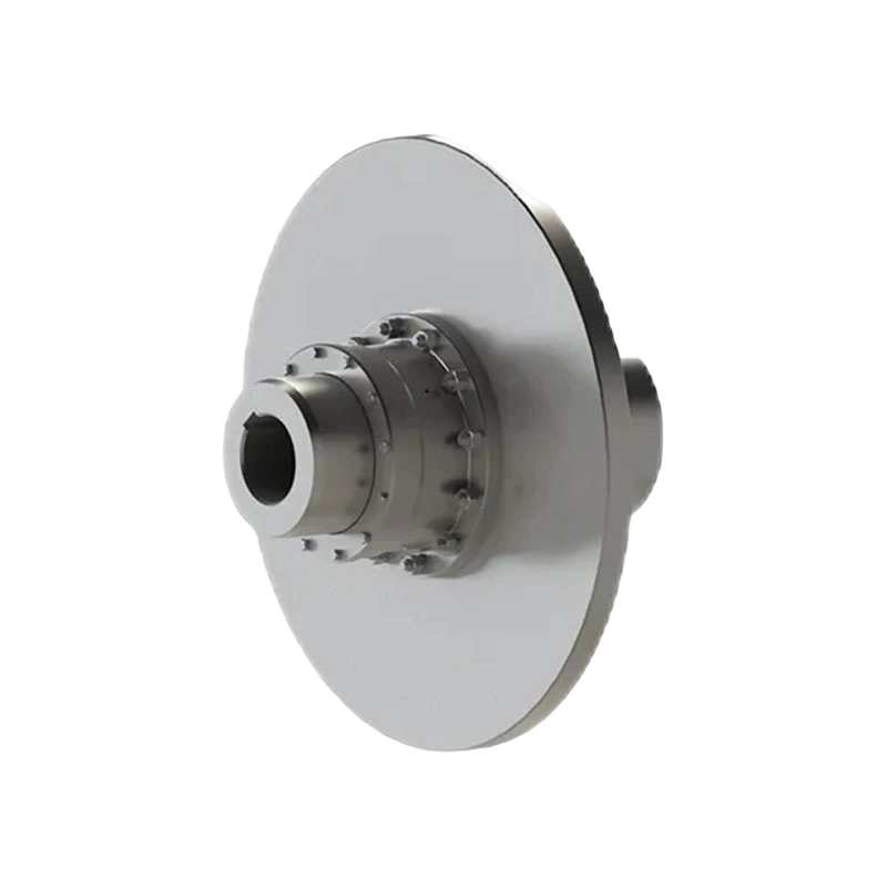
The coupling is classified as a flexible coupling with a non-metallic elastic element. Its design consists mainly of two flange half couplings with projecting claws, flange connectors, a plum-shaped elastic element, and the required bolts, nuts, and washers. The elastic element is fitted between the claws of the two half couplings. When the driving shaft rotates, torque passes through the claws and the elastic element to the driven shaft. The elastic element permits controlled relative movement while transmitting power efficiently.
Unlike a simple rigid flange connection, the MCS coupling is not required to operate only when two shafts are perfectly aligned. Unlike many metal-elastic couplings, it does not require lubrication for normal operation. Unlike some flexible couplings with complex multi-part assemblies, its structure is relatively straightforward, making installation, inspection, and replacement more convenient. These characteristics make it an attractive option for equipment designers and maintenance teams seeking dependable performance without unnecessary servicing complexity.
Product Overview and Operating Principle
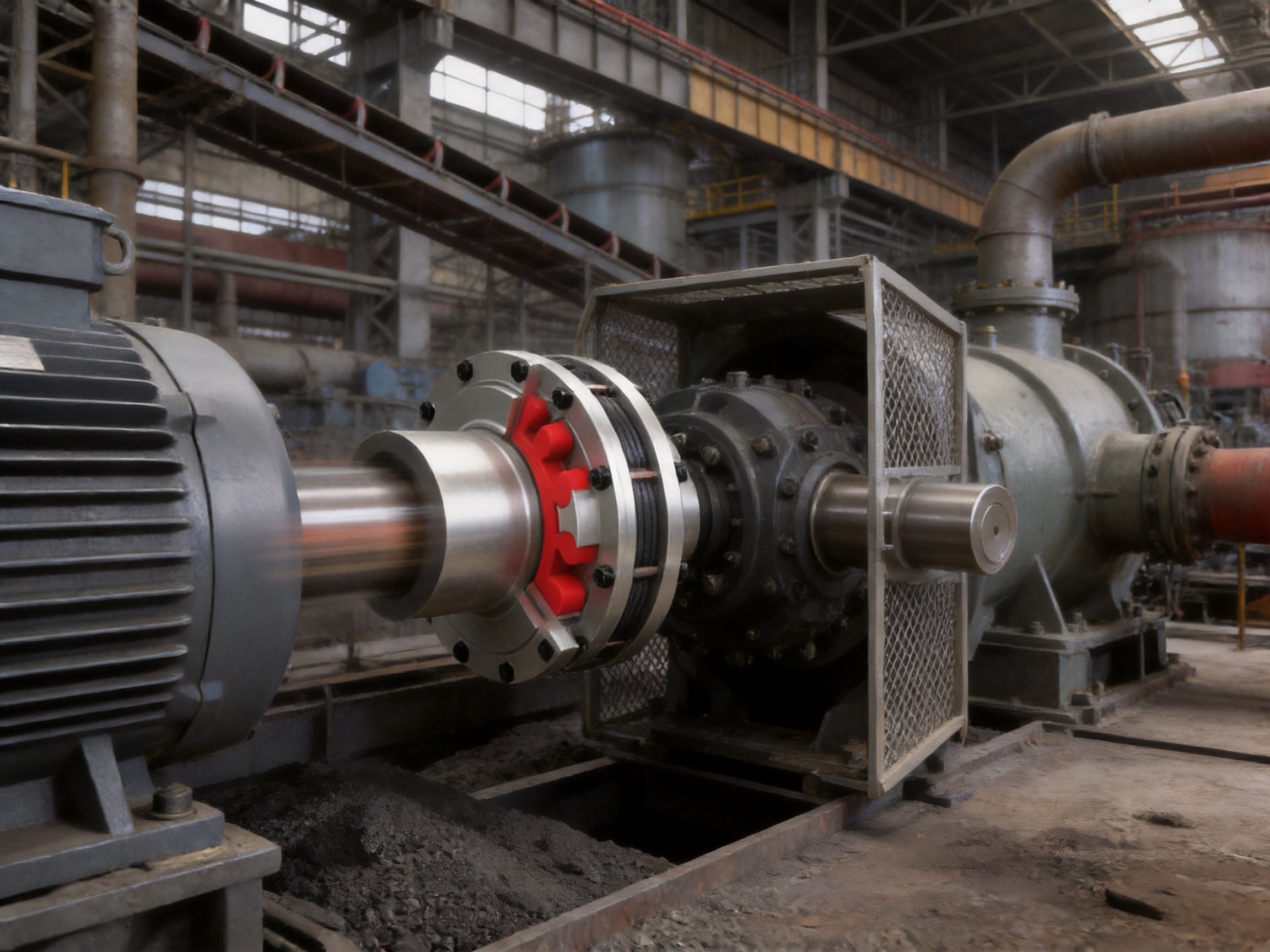
The MCS coupling uses a double-flange arrangement. Both ends of the coupling are provided with flange structures that can be connected directly to the flanges or mounting surfaces of associated equipment by bolted connections. This configuration gives the coupling a stable and clearly defined installation interface. It can be used where a shaft-mounted connection must be integrated with a motor, gearbox, pump, drive spindle, drum, or other industrial machine assembly.
Each flange half coupling contains projecting claws arranged around the connection area. The plum-shaped elastic element is positioned between these claws. During operation, the driving half coupling pushes against the elastic element, and the elastic element transfers the circumferential force to the driven half coupling. Because the element is resilient, it deforms in a controlled manner under load. This deformation permits the coupling to absorb vibration and compensate for limited shaft misalignment without interrupting torque transmission.
The elastic element is the functional center of the coupling. It provides the flexibility required for radial, angular, and axial displacement compensation. The coupling does not compensate for unlimited misalignment, and correct shaft alignment remains essential. However, the elastic element reduces the harmful effects of normal installation tolerances, foundation movement, thermal expansion, bearing clearance, and other operating variations.
The flange connection also contributes to installation stability. When the mating flange surfaces are correctly machined and the bolts are tightened according to the specified procedure, the physical relationship between the coupling and the connected equipment is well controlled. This can help maintain coaxiality and reduce the likelihood of installation-related vibration. The resulting assembly is particularly suitable for equipment where repeatable positioning and secure fastening are important.
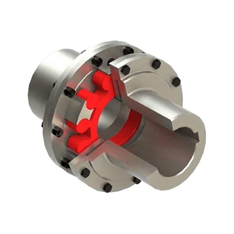
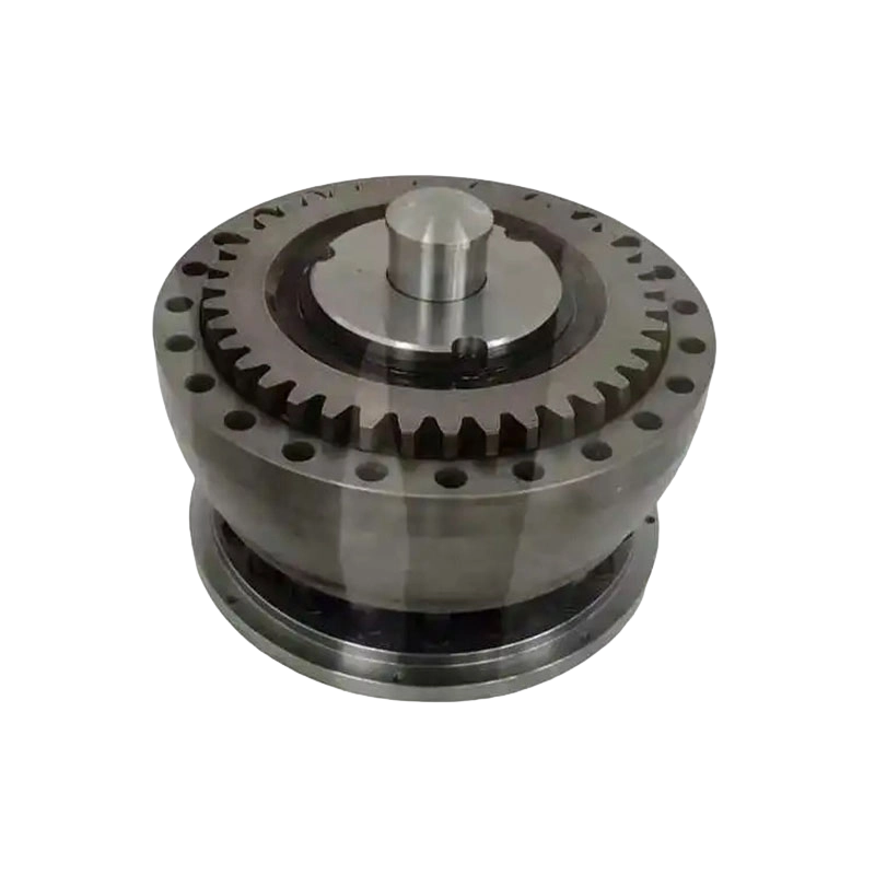
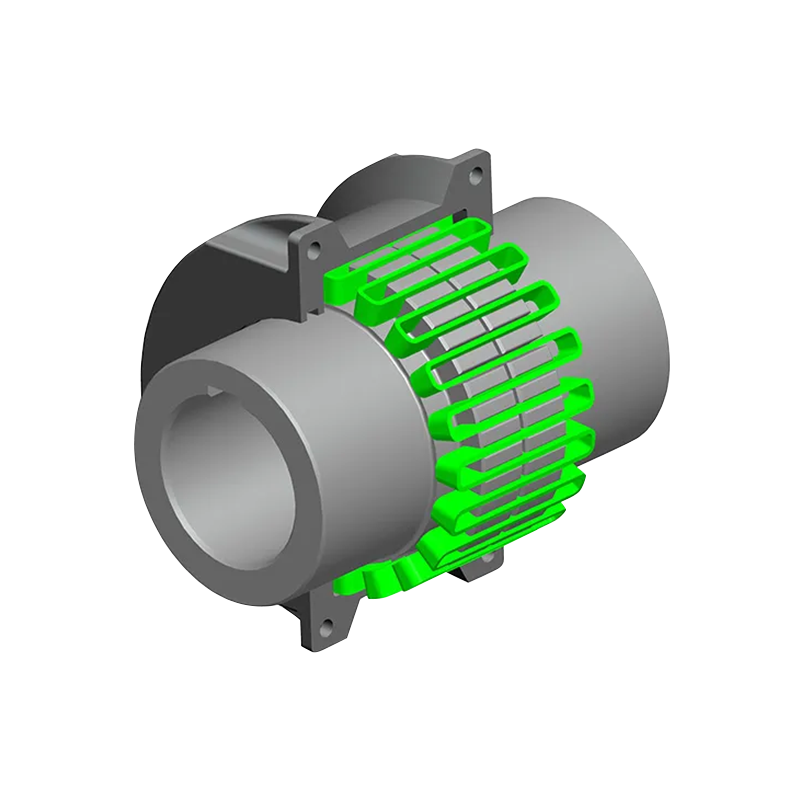
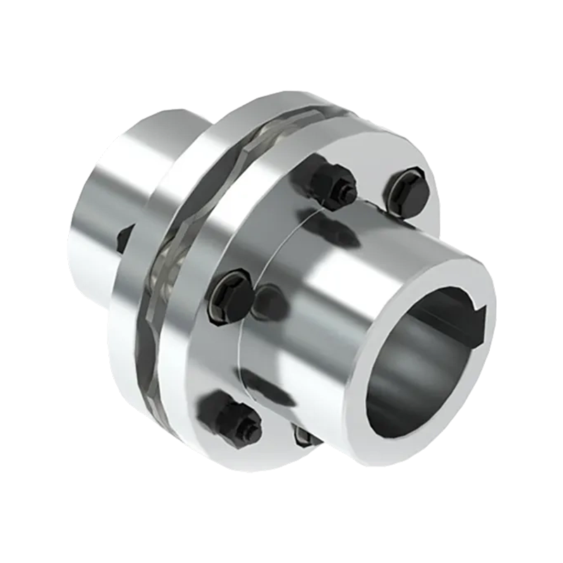
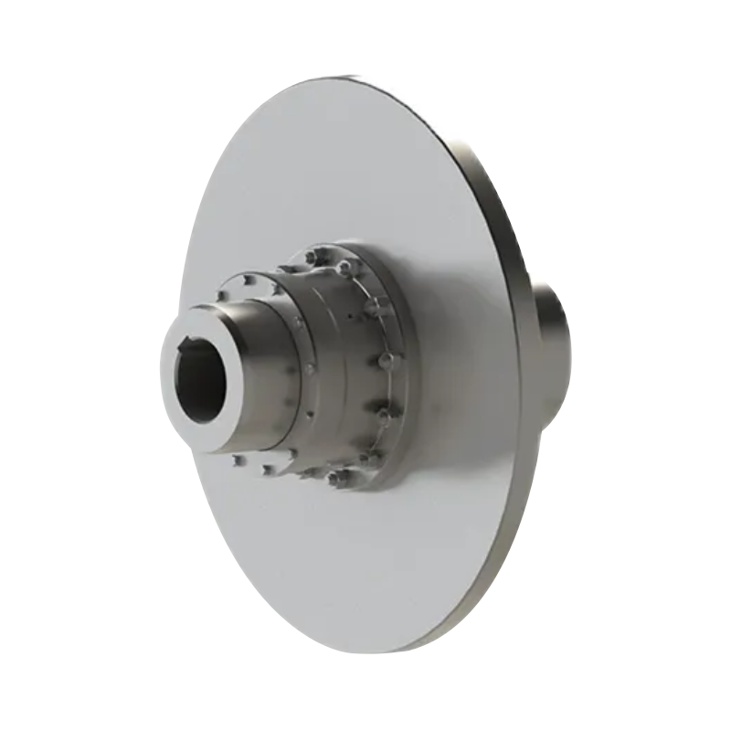
MCS type plum shaped elastic coupling (Q/YM 35014X-2018)
Structural Features of the MCS Coupling
Double-Flange Configuration
The double-flange configuration is one of the most important features of the MCS design. Many shaft couplings are installed only through hubs and keyways, requiring separate shaft-end arrangements and careful axial positioning. The MCS coupling adds a direct bolted flange interface, allowing it to be integrated with equipment that already uses flanged mounting surfaces. This can simplify the mechanical layout and reduce the need for additional adapters.
Flanged connections are also useful in heavy equipment because they provide a broad, stable contact area. A properly designed flange distributes connection forces over multiple bolts and a defined mounting face. This is advantageous where high torque, large shaft diameters, or frequent starting and stopping impose substantial loads on the connection.
Plum-Shaped Non-Metallic Elastic Element
The plum-shaped elastic element is positioned between the projecting claws of the two half couplings. Its geometry allows torque to be transmitted through several contact areas while maintaining flexibility. The element is made from a non-metallic elastic material selected for resilience, damping behavior, and suitability for the stated operating temperature range.
During torque transmission, the element absorbs a portion of the torsional shock that would otherwise pass directly into the shafts, bearings, gearbox, and connected machinery. This elastic action helps reduce sudden load transfer. It also contributes to lower operating noise and improved protection of connected components.
Because the elastic element is non-metallic, it provides useful electrical insulation between the two coupling halves. This can reduce the possibility of unwanted electrical current paths through the shaft line. In systems sensitive to electromagnetic interference, stray currents, or electrical potential differences, the insulating characteristic may support more stable operation. The complete system should still be evaluated by the equipment designer, particularly where electrical isolation is a safety-critical requirement.
Bolted Connection Components
The MCS assembly includes matching bolts, nuts, and washers. These components are not merely accessories; they are important to the structural reliability of the complete coupling. Correct bolt grade, tightening sequence, tightening torque, washer arrangement, and inspection practice all influence the performance of the flange connection.
During installation, the flange faces should be clean and free from burrs, scale, or foreign material. The shafts should be checked for dimensional accuracy, runout, and alignment. Bolts should be tightened evenly so that the flange surfaces seat uniformly. Maintenance personnel should periodically inspect the fasteners for loosening, corrosion, or damage, especially in equipment subject to high vibration or frequent reversing.
Performance Advantages
Multi-Directional Misalignment Compensation
A major advantage of the MCS coupling is its ability to accommodate radial, angular, and axial displacement. These three forms of displacement can occur independently or simultaneously.
Radial displacement occurs when the centerlines of two connected shafts are parallel but offset. Angular displacement occurs when the shaft centerlines intersect at an angle. Axial displacement occurs when the shafts move toward or away from one another along their common axis. In operating machinery, these conditions may result from assembly tolerances, thermal growth, foundation settlement, bearing movement, or dynamic loading.
The elastic element deforms to accommodate these limited movements. This reduces the transmission of excessive reaction forces into the bearings and shafts. It also helps prevent premature wear caused by an overly rigid connection. Nevertheless, the coupling should not be used as a substitute for alignment. Excessive misalignment can generate heat, accelerate elastic element wear, increase vibration, and reduce service life.
High Transmission Efficiency
The product description specifies transmission efficiency of more than 99 percent under suitable operating conditions. This high efficiency results from the direct torque path through the flange half couplings and elastic element. The coupling is designed to provide flexibility without introducing unnecessary sliding friction or continuous lubrication losses.
High transmission efficiency is important in industrial systems that operate for long periods or handle high power. Lower mechanical losses can support energy efficiency and reduce heat generation. The actual efficiency achieved in service depends on torque, speed, alignment, elastic element condition, temperature, installation quality, and the characteristics of the connected machines.
Vibration and Shock Absorption
Industrial drives rarely operate under perfectly smooth load conditions. Motors may produce starting torque surges, gearboxes may generate periodic fluctuations, and working machines may impose intermittent or impact loads. The MCS elastic element acts as a buffer between the driving and driven sides.
When a sudden load change occurs, the elastic element deforms rather than transferring the entire disturbance instantaneously through the shaft line. This can reduce torsional shock and help protect gears, bearings, keys, shafts, and other drive components. The same damping effect can reduce mechanical noise and improve the working environment around the machine.
Vibration reduction also supports equipment life. Excessive vibration can loosen fasteners, damage seals, fatigue brackets, and increase bearing loads. By absorbing a portion of the vibration energy, the coupling contributes to a more stable transmission system. The level of improvement depends on the source and frequency of the vibration, so system-level analysis remains recommended for critical machinery.
Electrical Insulation
The non-metallic elastic element creates electrical separation between the two metal coupling halves. This feature can be valuable in systems where electrical continuity through the shaft line is undesirable. It may help limit the transmission of stray currents and reduce the risk of electrical interference affecting sensitive equipment.
Electrical insulation can be especially relevant in motor-driven systems, generator assemblies, instrumentation-related machinery, and installations where different components may operate at different electrical potentials. The required insulation resistance and any applicable electrical protection measures should be confirmed for the specific application.
No Routine Lubrication
The MCS coupling is designed for operation without routine lubrication. This is a meaningful practical advantage over couplings that depend on grease or oil for the protection of sliding or meshing surfaces. Eliminating regular lubrication reduces the number of maintenance tasks and avoids problems associated with leakage, contamination, incorrect lubricant selection, or missed service intervals.
Although no lubrication is required for the elastic element under normal conditions, the coupling should still be inspected. Maintenance personnel should examine the elastic element for cracking, hardening, tearing, excessive compression, abrasion, or permanent deformation. The flange bolts and connected shaft surfaces should also be checked as part of the equipment’s preventive maintenance program.
Suitability for Frequent Starting and Reversing
The coupling supports applications involving frequent starting and forward and reverse rotation. This capability is important for cranes, lifting equipment, conveyors, reversing drives, positioning machinery, and process equipment with cyclic operation.
Frequent starting generates repeated acceleration torque, while reversing subjects the elastic element and connection components to changing torque direction. The MCS structure is intended to buffer these changes and maintain a reliable mechanical connection. Application selection should consider the number of starts per hour, reversing frequency, peak torque, acceleration time, and the inertia of the driven machine.
Technical Parameters and Size Range
The MCS series includes fourteen standard sizes, from MCS1 to MCS14. The nominal torque range extends from 28 N·m to 14,000 N·m, while the maximum torque range extends from 50 N·m to 25,200 N·m. The maximum listed allowable speed is 8,500 r/min for the smallest size. Allowable speed decreases as coupling size and torque capacity increase.
The available shaft hole diameters cover a broad range from 12 mm to 160 mm, depending on the selected coupling size. Some shaft hole dimensions are marked with an asterisk in the technical schedule. Such marks should be confirmed against the manufacturer’s dimensional drawing or ordering documentation before production and installation.
| Type | Nominal Torque Tn (N·m) | Maximum Torque Tmax (N·m) | Allowable Speed (r/min) | L (mm) | L0 (mm) | D (mm) | D1 (mm) | Elastic Element | Mass (kg) |
| MCS1 | 28 | 50 | 8500 | 35 | 98 | 50 | 90 | MT1 | 1.206 |
| MCS2 | 50 | 100 | 7600 | 38 | 108 | 60 | 100 | MT2 | 1.648 |
| MCS3 | 112 | 200 | 6900 | 40 | 117 | 70 | 110 | MT3 | 2.357 |
| MCS4 | 160 | 288 | 6200 | 45 | 130 | 85 | 125 | MT4 | 3.556 |
| MCS5 | 355 | 640 | 5000 | 50 | 150 | 105 | 150 | MT5 | 6.361 |
| MCS6 | 450 | 810 | 4100 | 55 | 167 | 125 | 185 | MT6 | 10.768 |
| MCS7 | 710 | 1280 | 3700 | 60 | 185 | 145 | 205 | MT7 | 15.302 |
| MCS8 | 1250 | 2250 | 3100 | 70 | 209 | 168 | 240 | MT8 | 22.717 |
| MCS9 | 2000 | 3600 | 2800 | 80 | 240 | 198 | 270 | MT9 | 34.439 |
| MCS10 | 3150 | 5670 | 2500 | 90 | 268 | 228 | 305 | MT10 | 51.358 |
| MCS11 | 5000 | 9000 | 2200 | 100 | 308 | 258 | 350 | MT11 | 81.302 |
| MCS12 | 7100 | 12780 | 1900 | 115 | 345 | 298 | 400 | MT12 | 115.53 |
| MCS13 | 12500 | 22500 | 1600 | 125 | 373 | 358 | 460 | MT13 | 161.79 |
| MCS14 | 14000 | 25200 | 1500 | 135 | 383 | 400 | 500 | MT14 | 196.30 |
The dimensions in the table provide an initial basis for equipment layout and model selection. The shaft hole options are size-specific and should be confirmed before ordering. Engineers should also verify the required bore tolerance, keyway configuration, flange bolt pattern, axial space, guard clearance, and installation method using the applicable production drawing.
Understanding Torque Selection
Nominal torque is the principal reference value for normal continuous service. Maximum torque represents the higher torque level that the coupling may withstand for limited or transient conditions when the application is properly evaluated. The maximum value should not be treated as the continuous operating rating.
To select an appropriate model, the required operating torque should be calculated from transmitted power and speed. A commonly used relationship is T = 9550P/n, where T is torque in N·m, P is power in kW, and n is rotational speed in r/min. Service factors must then be applied to account for starting, stopping, impact, load fluctuation, reversing, and the characteristics of the prime mover and driven machine.
For equipment with high inertia or repeated shock loading, selecting only by average torque may be inadequate. The engineer should compare the calculated design torque with the nominal and maximum torque values and verify that the operating speed remains below the allowable speed for the selected model. Temperature, environmental exposure, and shaft geometry must also be included in the selection process.
Advantages Compared with Alternative Coupling Designs
Compared with Rigid Flange Couplings
Rigid couplings provide a solid connection and can be effective where shafts are permanently aligned and no relative movement is expected. However, they transfer misalignment forces directly into the shaft and bearing system. They also provide little protection against torsional shock or vibration.
The MCS coupling retains the secure bolted flange concept while adding elastic flexibility. It can accommodate limited displacement, absorb vibration, and soften torque shocks. This makes it more forgiving in practical industrial installations where alignment changes may occur during operation. A rigid coupling may remain preferable for applications requiring an absolutely fixed shaft relationship, but it offers fewer protective characteristics than the MCS design.
Compared with Lubricated Gear Couplings
Gear couplings can transmit high torque and accommodate certain forms of misalignment, but they normally require lubrication and periodic seal inspection. Contamination, lubricant degradation, or seal failure can affect their service life. Their tooth surfaces may also generate backlash and require more complex maintenance procedures.
The MCS coupling operates without routine lubrication and uses a replaceable non-metallic elastic element instead of meshing gear teeth. This can reduce maintenance labor and simplify spare-parts management. It also provides electrical insulation that is not normally inherent in an all-metal gear coupling. Gear couplings may be selected for very high torque, high temperature, or specialized applications, while the MCS is particularly attractive where simplicity, damping, and low maintenance are priorities.
Compared with Metal Disc or Diaphragm Couplings
Metal disc and diaphragm couplings offer high torsional stiffness and may be suitable for precision positioning, high-speed systems, or applications requiring precise angular control. Their metal flexible elements, however, can transmit more vibration and may be more sensitive to certain installation conditions. They also require careful attention to disc or diaphragm fatigue and alignment limitations.
The MCS plum-shaped elastic element provides stronger damping and shock absorption. Its non-metallic construction also provides electrical insulation. For heavy industrial equipment where impact loads, vibration, and frequent starts are more important than very high torsional stiffness, the MCS design can provide a better balance of flexibility and reliability.
Compared with Jaw Couplings
Jaw couplings also use an elastic element between two hubs and are known for compact construction and convenient replacement. However, their typical connection arrangement is based on shaft-mounted hubs rather than the double-flange installation interface of the MCS. When a machine requires direct bolted attachment to flanges or equipment mounting surfaces, the MCS configuration may simplify the mechanical arrangement.
The MCS series also extends to a much higher nominal torque range than many small jaw coupling arrangements. Its larger models are designed for substantial industrial drive systems, while smaller jaw couplings are often used in light-duty or precision applications. The best choice depends on the required torque, speed, available space, shaft arrangement, and maintenance requirements.
Compared with Sleeve or Pin Couplings
Elastic sleeve and pin couplings can provide useful flexibility and shock absorption, but their installation dimensions and replacement procedures differ from those of the MCS. The MCS double-flange structure can provide a more direct interface for equipment with flanged output or input surfaces. Its elastic element is also configured specifically for the claw-and-flange arrangement, allowing the coupling to combine a secure connection with non-metallic damping.
In all comparisons, the correct selection depends on the application rather than on one universal product advantage. The MCS coupling is especially competitive when the design requires flange mounting, multi-directional compensation, high torque capacity, electrical insulation, no routine lubrication, and suitability for repeated starting or reversing.
Manufacturing Strengths and Quality Control
Zhongye Heavy Industry Technology (Zhenjiang) Co., Ltd. integrates product research and development, manufacturing, and sales. Its product range includes toothed couplings, elastic sleeve pin couplings, elastic pin couplings, gear couplings with elastic pins, universal couplings, tire couplings, jaw couplings, star couplings, diaphragm couplings, drum couplings, grid couplings, Oldham couplings, flange couplings, clip-shell couplings, roller-chain couplings, safety couplings, and customized non-standard couplings.
This broad product portfolio supports practical engineering experience across multiple coupling technologies. Knowledge gained from manufacturing different coupling types can assist with material selection, torque transmission analysis, machining accuracy, balancing requirements, sealing arrangements, and application-specific design. It also allows the company to recommend alternatives when the operating conditions do not suit a standard MCS model.
Dedicated Production Facilities
The company’s new workshop covers approximately 16,463.52 square meters. The facility includes a heavy workshop of approximately 5,500 square meters, a precision workshop of approximately 4,600 square meters, an office building and gymnasium of approximately 2,000 square meters, a dining hall of approximately 500 square meters, a warehouse of approximately 1,000 square meters, and approximately 3,563 square meters assigned to roads, landscaping, and parking.
The separation of heavy and precision production areas is beneficial for coupling manufacturing. Large coupling components may require substantial handling capacity, robust machine tools, and sufficient assembly space. At the same time, flange faces, shaft bores, claw geometry, and bolt patterns require controlled machining accuracy. A facility that provides both heavy-duty working space and a dedicated precision workshop is well suited to producing coupling components across a broad size range.
Engineering and Non-Standard Manufacturing
Standard MCS models cover a wide range of torque, speed, and shaft hole requirements. However, industrial equipment often has special constraints. These may include unusual shaft diameters, non-standard keyways, special flange dimensions, modified bolt circles, restricted axial length, different materials, special coatings, high-temperature requirements, or integration with existing machinery.
The company undertakes the design and manufacture of non-standard couplings. This capability is important for original equipment manufacturers and maintenance departments replacing obsolete or imported coupling products. A customized solution can be developed around actual shaft drawings, load data, installation dimensions, and environmental conditions rather than forcing the machine to accommodate an unsuitable standard model.
Customization should begin with complete technical information. Useful documents include shaft diameter and tolerance, shaft extension length, keyway dimensions, flange drawings, bolt-hole arrangement, rotational speed, power, operating torque, peak torque, start-stop frequency, ambient temperature, dust or water exposure, and expected service life. Providing accurate data allows the supplier to verify the mechanical design and avoid costly modifications later.
Testing and Quality Assurance
Reliable coupling production requires more than visual inspection. Critical dimensions such as shaft bores, flange runout, outside diameter, axial length, claw geometry, and bolt-hole location should be checked against approved drawings. The elastic elements should be inspected for dimensional consistency and material quality. Finished assemblies should be reviewed for fit, balance, surface condition, and correct component matching.
The company states that it has advanced testing facilities, strict quality control, and production guarantees. These capabilities support systematic verification from raw material and component processing through final assembly. For high-speed or high-torque couplings, dynamic balance and runout control are especially important because even a small imbalance can generate significant centrifugal forces at operating speed.
Quality management according to ISO 9001 principles provides a framework for documented processes, traceability, inspection records, corrective action, and continuous improvement. Compliance with the Q/YM 35014X-2018 product standard gives the MCS design a defined technical basis for its structure and performance parameters. Customers with specialized requirements may request inspection documentation, material certificates, dimensional reports, or other quality records as part of the purchasing agreement.
Material and Process Considerations
The metal half couplings must provide adequate strength, dimensional stability, wear resistance, and machinability. The selected material and heat-treatment condition should correspond to the coupling size, torque requirement, operating environment, and manufacturing specification. Machining processes should maintain accurate concentricity between the bore and the external coupling geometry.
The flange faces should be manufactured to provide reliable contact with the mating equipment. Bolt holes must be positioned accurately so that the assembly can be installed without forced alignment. Keyways and shaft bores should be checked for correct fit, since excessive clearance can produce fretting and impact while insufficient clearance can complicate installation.
The non-metallic elastic element requires controlled material processing. Its hardness, resilience, dimensional accuracy, temperature resistance, and aging behavior influence coupling performance. Consistent production is important because variations in elastic properties can change torsional stiffness, damping, misalignment capacity, and service life. Proper storage is also necessary to protect elastic elements from excessive heat, direct sunlight, ozone, oils, solvents, and mechanical deformation.
Application Areas
Metallurgical Equipment
Metallurgical machinery often operates under high loads, elevated temperatures, vibration, and frequent load changes. Rolling mills, cooling systems, conveying equipment, processing lines, and auxiliary drives can benefit from a coupling that buffers shock and tolerates limited misalignment. The MCS series offers a broad torque range that allows selection for both auxiliary drives and larger power transmission systems.
Where hot materials or radiant heat are present, the coupling should be positioned and protected according to the permitted temperature range. The specified working environment for the MCS series is from -35°C to +80°C. If the ambient or transmitted heat exceeds this range, special material selection or thermal shielding should be considered.
Mining Equipment
Mining machinery is exposed to dust, impact, vibration, and irregular loading. Conveyors, crushers, feeders, pumps, hoists, and screening equipment may experience sudden torque changes when material flow varies or blockages occur. The MCS elastic element can reduce the severity of these disturbances and help protect connected shafts and bearings.
In dusty environments, a suitable guard should be used to protect personnel and prevent large contaminants from entering the coupling area. Inspection intervals should be adapted to the severity of the environment. Dust accumulation, abrasive particles, and moisture may influence the condition of the elastic element and fasteners even when the coupling itself requires no lubrication.
Water Conservancy and Pumping Systems
Pumps and water equipment often require dependable continuous operation. The MCS coupling can be used in pump drives where flange mounting, vibration reduction, and electrical insulation are beneficial. Its no-lubrication design reduces the possibility of lubricant contamination around water-handling equipment.
For outdoor or wet installations, the metal components should be protected against corrosion through appropriate material selection, coating, or environmental protection. The coupling guard should allow sufficient ventilation while preventing accidental contact and excessive water or debris accumulation.
Lifting and Transportation Equipment
Lifting equipment, hoists, cranes, and transportation machinery may start, stop, accelerate, decelerate, and reverse frequently. These operating cycles create demanding torsional conditions. The MCS coupling’s elastic element helps absorb acceleration shock and changing torque direction.
Because lifting applications can involve safety-critical loads, coupling selection must include the complete duty cycle and applicable safety factors. The nominal torque, maximum torque, allowable speed, shaft connection, bolt tightening, guarding, and inspection program should all be reviewed by qualified engineers. The coupling should never be operated beyond its rated conditions or used without an appropriate guard.
Papermaking Machinery
Paper equipment often includes long transmission lines, rollers, pumps, fans, cutters, and auxiliary drives. These systems may require smooth torque transmission, low vibration, and reliable continuous operation. The MCS coupling can provide damping and alignment tolerance while avoiding routine lubrication near process areas.
High-speed portions of paper machinery require careful attention to allowable speed and dynamic balance. The smaller MCS models offer higher allowable speeds, while the larger models provide greater torque capacity at lower speeds. Selection should always balance both requirements rather than choosing a size solely by torque.
Port and Material-Handling Equipment
Port machinery commonly operates outdoors and may be exposed to wind, moisture, salt-laden air, impact loads, and repeated duty cycles. Conveyors, winches, hoists, ship loaders, and transfer systems can require both flexible torque transmission and dependable flange mounting.
For coastal environments, corrosion protection and fastener selection are particularly important. Regular inspection should focus on flange bolts, exposed surfaces, elastic element condition, and guard integrity. The coupling’s mechanical advantages are best realized when environmental protection and preventive maintenance are properly applied.
Installation Recommendations
Before installation, confirm that the supplied coupling model matches the approved equipment drawing. Check the model designation, nominal torque, allowable speed, shaft hole diameters, keyways, flange dimensions, elastic element type, and bolt configuration. Do not assume that a visually similar coupling has identical dimensions or performance.
Inspect the shafts and mating flanges. Shaft surfaces should be free of burrs, rust, oil contamination, and impact damage. The shaft bores and keys should be clean and correctly fitted. Flange faces should be flat, clean, and free of foreign material. Any damage that prevents full contact should be corrected before assembly.
Align the connected equipment before final bolt tightening. The shafts should be checked for radial offset, angular deviation, and axial position. Although the MCS coupling compensates for limited displacement, minimizing misalignment reduces elastic element stress and improves service life. Alignment should be checked using appropriate measuring tools rather than relying solely on visual judgment.
Install the elastic element carefully between the claws. Do not force it into position with sharp tools or strike it with a hammer. Damage introduced during installation may not be immediately visible but can lead to premature failure. Confirm that the element is seated uniformly and that the claws do not contact metal-to-metal in a way that bypasses the elastic element during normal operation.
Install bolts, nuts, and washers according to the approved assembly procedure. Tighten the bolts gradually in a crosswise or other specified sequence so that the flange faces seat evenly. Use the specified tightening torque and verify that the bolts are not bottoming out or contacting nearby components. After the first operating period, recheck the connection if required by the maintenance procedure.
A suitable guard must be installed around the rotating coupling. The guard should prevent personnel contact, contain components in the unlikely event of a failure, and provide adequate access for inspection. It should not press against the coupling or restrict required movement. Ventilation and clearance should be sufficient to prevent excessive heat accumulation.
Maintenance and Service Life
The MCS coupling is designed for low maintenance, but low maintenance does not mean zero inspection. A planned inspection program helps identify problems before they cause unplanned downtime. Inspection frequency should be based on speed, load, reversing frequency, environment, operating temperature, and the criticality of the equipment.
Inspect the elastic element for cracks, cuts, hardening, softening, surface deterioration, excessive wear, permanent deformation, and unusual compression. Compare its condition with a new element when necessary. If the element shows significant damage or has lost its intended elasticity, it should be replaced promptly.
Check the coupling for abnormal noise, vibration, heat, or odor during operation. A new rattling sound may indicate loose fasteners, excessive clearance, damaged claws, or elastic element deterioration. Increased vibration may result from misalignment, imbalance, shaft damage, bearing failure, or coupling wear. The coupling should not be blamed automatically without checking the complete drive system.
Inspect bolts and nuts for loosening, corrosion, thread damage, and loss of clamping force. Verify that the flange connection remains secure. Examine the shaft and keyway for fretting, cracks, deformation, or movement. Any sign of relative movement between the hub or flange and the shaft should be investigated immediately.
Replacement of the elastic element is generally simpler than replacing a complete coupling. However, the replacement element must be the correct type and size. Do not substitute an element solely because it appears to fit. Differences in material hardness, geometry, or dimensions can change torque transmission and damping performance.
Before maintenance, isolate the prime mover, lock out the energy source, verify zero movement, and follow the site’s safety procedures. Never inspect or touch a rotating coupling. After maintenance, reinstall all guards and confirm that tools, loose parts, and foreign objects have been removed before restarting the equipment.
Engineering Support and Customization
One of the company’s important strengths is the ability to provide technical support before, during, and after purchase. Coupling selection can involve more than matching a torque number. Engineers may need to evaluate speed, shaft dimensions, peak loads, misalignment, ambient conditions, installation space, electrical isolation, balancing, and compatibility with existing equipment.
Zhongye Heavy Industry Technology (Zhenjiang) Co., Ltd. supports standard products as well as customized and non-standard coupling solutions. This is useful for customers replacing an existing coupling where the original product is unavailable or where the machine has a unique flange pattern. A customized MCS-style solution may be developed around the customer’s drawings and operating data, subject to engineering review.
Technical communication is most effective when the customer supplies complete information. A typical inquiry should state the motor power, speed, shaft diameter, keyway, driven-machine torque, starting method, reversing frequency, operating temperature, environmental exposure, installation orientation, available space, and required quantity. Photos and dimensional drawings of the existing assembly can also help identify practical constraints.
For large or critical equipment, customers may request preliminary calculations, dimensional drawings, material information, inspection documents, and installation guidance. Cooperation between the manufacturer and equipment designer at the early design stage can prevent interference problems and ensure that the coupling guard, access space, and maintenance route are included in the machine layout.
Why the MCS Series Is a Practical Industrial Choice
The MCS series combines several features that are often requested together but are not always available in one coupling design. It provides a flanged connection for installation stability, a non-metallic elastic element for vibration damping, compensation for several types of limited misalignment, electrical insulation, no routine lubrication, and a wide torque and bore range.
Its fourteen standard sizes allow the same basic product concept to be applied across a broad range of machinery. The series begins with a nominal torque of 28 N·m and extends to 14,000 N·m. Shaft hole options range from small industrial shaft diameters to large drive shafts up to 160 mm, depending on the model. This range supports standardized equipment design and simplifies product selection across different machine platforms.
The design is also practical from a maintenance perspective. The coupling does not depend on a lubrication system, and the elastic element can be inspected as an identifiable service component. A clear flange assembly makes the connection easy to understand for installation and maintenance personnel. These qualities can help reduce routine maintenance time and improve equipment availability.
Compared with couplings designed primarily for rigid, precision, or purely high-speed operation, the MCS series places greater emphasis on balanced industrial performance. It is intended to transmit torque efficiently while providing useful flexibility and damping. This makes it particularly suitable for heavy machinery where operating conditions include vibration, shock, thermal movement, or repeated changes in rotational direction.
The product is supported by a manufacturer with experience in a wide range of coupling technologies, dedicated heavy and precision workshops, testing capabilities, quality-control procedures, and non-standard design support. Together, these factors provide customers with more than a catalog component. They provide a path from application analysis and model selection to manufacturing, inspection, delivery, installation, and after-sales support.
Selection Checklist
Before placing an order, confirm the following technical points:
1. Required continuous operating torque and calculated design torque.
2. Peak or transient torque during starting, stopping, impact, and reversing.
3. Operating speed and the allowable speed of the proposed MCS model.
4. Driving and driven shaft diameters, bore tolerances, keyways, and shaft extensions.
5. Required flange dimensions, bolt-hole pattern, and axial installation length.
6. Expected radial, angular, and axial misalignment.
7. Ambient temperature and any heat transferred from nearby equipment.
8. Exposure to water, dust, oil, chemicals, salt spray, or abrasive particles.
9. Requirement for electrical insulation or stray-current protection.
10. Guarding, access, balancing, and maintenance requirements.
11. Required documentation, inspection records, certificates, and customized drawings.
12. Quantity of spare elastic elements and recommended replacement intervals.
A coupling selected with these points in mind is more likely to deliver the expected service life and operating stability. When any requirement is uncertain, technical consultation should be obtained before final selection.
Frequently Asked Questions
What type of coupling is the MCS product?
The MCS is a flexible coupling with a non-metallic elastic element. It uses a double-flange structure and a plum-shaped elastic element positioned between projecting claws on two flange half couplings.
What standard does the MCS coupling comply with?
The product is described as complying with Q/YM 35014X-2018. The applicable technical documentation should be reviewed for detailed dimensional, material, performance, and inspection requirements.
What is the torque range of the MCS series?
The nominal torque range is 28 N·m to 14,000 N·m. The listed maximum torque range is 50 N·m to 25,200 N·m, depending on the selected model.
What is the maximum speed available?
The highest listed allowable speed is 8,500 r/min for the MCS1 model. Allowable speed decreases for larger models, reaching 1,500 r/min for MCS14. The speed rating of the selected model must not be exceeded.
What shaft hole sizes are available?
The series covers shaft hole diameters from 12 mm to 160 mm, with the available bore options depending on the coupling model. Exact bore dimensions, tolerances, and keyways should be confirmed from the production drawing.
Does the coupling require lubrication?
No routine lubrication is required for normal operation. The coupling should still receive regular inspections for elastic element condition, bolt security, alignment, corrosion, abnormal noise, and vibration.
Can the MCS coupling compensate for shaft misalignment?
Yes. Its elastic element can compensate for limited radial, angular, and axial displacement. The coupling should nevertheless be installed with accurate alignment because excessive misalignment can reduce service life and increase vibration.
Can it be used for reversing applications?
Yes. The product is suitable for applications involving frequent starting and forward and reverse rotation, provided that the torque, speed, duty cycle, and service factor remain within the selected model’s capabilities.
Does the elastic element provide electrical insulation?
Yes. The non-metallic elastic element helps electrically separate the two metal coupling halves. The required insulation performance should be verified for the specific electrical system and safety application.
What operating temperature range is specified?
The stated working environment is from -35°C to +80°C. Applications outside this range require special evaluation and may require alternative elastic materials or thermal protection.
What industries use the MCS coupling?
Typical applications include metallurgy, mining, water conservancy, lifting and transportation, papermaking machinery, port equipment, and other industrial systems requiring reliable flexible torque transmission.
Can customized couplings be manufactured?
Yes. The manufacturer undertakes the design and manufacture of non-standard couplings. Customization may include special shaft bores, keyways, flange dimensions, bolt patterns, materials, coatings, or installation dimensions, subject to engineering review.
What information is required for product selection?
Important information includes motor power, speed, operating torque, peak torque, shaft sizes, keyways, flange dimensions, load characteristics, start-stop frequency, misalignment, temperature, environment, available space, and electrical insulation requirements.
How should the elastic element be maintained?
Inspect it for cracks, cuts, hardening, softening, abrasion, deformation, and other deterioration. Replace it with the correct specified element if damage or significant loss of elasticity is found.
Is a coupling guard necessary?
Yes. A suitable guard should be installed around the rotating coupling to protect personnel and prevent accidental contact. The guard must provide adequate clearance and should not interfere with coupling movement or inspection.
Conclusion
The MCS type plum-shaped elastic coupling is a versatile solution for industrial shaft connection where secure flange mounting, flexible torque transmission, vibration absorption, electrical insulation, and low maintenance are important. Its double-flange structure supports stable installation, while the non-metallic elastic element compensates for limited radial, angular, and axial displacement and helps protect connected machinery from shock and vibration.
With fourteen standard sizes, nominal torque ratings from 28 N·m to 14,000 N·m, allowable speeds up to 8,500 r/min, and shaft hole options extending to 160 mm, the series serves a wide range of machinery. Its suitability for frequent starting and reversing makes it especially useful in lifting, transport, mining, metallurgy, and other cyclic-duty applications.
The product’s value is strengthened by the manufacturer’s integrated research, manufacturing, sales, engineering, testing, and service capabilities. Heavy and precision workshops, documented quality control, ISO 9001-related management practices, broad coupling expertise, and non-standard design support provide a strong foundation for dependable supply. When correctly selected, installed, guarded, and maintained, the MCS coupling can contribute to efficient power transmission, reduced vibration, longer equipment life, and improved operational reliability.
References
1. Q/YM 35014X-2018, technical standard for the MCS plum-shaped elastic coupling.
2. MCS Type Plum-Shaped Elastic Coupling, basic parameters and main dimensional schedule supplied with the product documentation.
3. ISO 9001, Quality management systems: requirements.
4. General industrial coupling selection principles covering torque, speed, alignment, service factors, guarding, and maintenance.
5. Manufacturer-provided technical information for MCS series coupling construction, application range, performance characteristics, and customization support.
Product: MCS type plum shaped elastic coupling (Q/YM 35014X-2018)
- Quick Links
- About
- Products
- Our Service
- News & Events
- Contact
- Products Series
- Flexible Couplings with Non-Elastic Elements
- Flexible Couplings with Metal Elastic Elements
- Flexible Couplings with Non-Metallic Elastic Elements
- Safety Coupling
- Rigid Coupling
- Contact Us
- Tel : +86 511 8572 3800 +86 511 8572 3900
- Mobile : +86 15106109009
- Email : sales@couplingzy.com
- Add:No.1 Zhongye Yingbin Avenue, Gaozi Street, Dantu Economic Development Zone, Zhenjiang City, Jiangsu Province, China.


