:+86 15106109009
:sales@couplingzy.com


 English
  русский
  Español
  عربى
عربى  Português
  Deutsch
  Türk
Türk  Indonesia

GCP Drum Gear Coupling with Brake Disc: Integrated Heavy-Duty Transmission and Controlled Braking
Content
- 1 1. Product Concept and Industrial Role
- 2 2. Main Advantages of the GCP Design
- 3 3. Technical Range and Selection Data
- 4 4. How the Coupling Works During Operation
- 5 5. Structural Design Features
- 6 6. Advantages Compared with Alternative Coupling Arrangements
- 7 7. Applications in Heavy Industry
- 8 8. Manufacturing Strengths and Quality Advantages
- 9 9. Engineering Selection Procedure
- 10 10. Installation Recommendations
- 11 11. Maintenance and Service Life
- 12 12. Safety Considerations
- 13 13. Why the Product Is Suitable for International Industrial Projects
- 14 14. Practical Comparison of Product Benefits
- 15 15. Customer Support and Supply Capability
- 16 16. Frequently Asked Questions
- 16.1 Q1: What is the primary purpose of the GCP drum gear coupling with brake disc?
- 16.2 Q2: What standard is associated with this product?
- 16.3 Q3: What is the torque range of the GCP series?
- 16.4 Q4: What is the maximum allowable speed?
- 16.5 Q5: What brake disc diameters are available?
- 16.6 Q6: Can the coupling compensate for shaft misalignment?
- 16.7 Q7: Does the coupling include the complete braking system?
- 16.8 Q8: How is the coupling lubricated?
- 16.9 Q9: Can the product be customized?
- 16.10 Q10: What information is needed for model selection?
- 16.11 Q11: Is the product suitable for mining equipment?
- 16.12 Q12: Why is brake disc inertia important?
- 16.13 Q13: Can the brake disc be used to hold a suspended load?
- 16.14 Q14: What are the main maintenance concerns?
- 16.15 Q15: What makes this product different from a standard gear coupling?
- 17 17. Conclusion
- 18 References
- 19 Product: GCP Drum gear coupling with brake disc(Q/YG 13012X-2018)
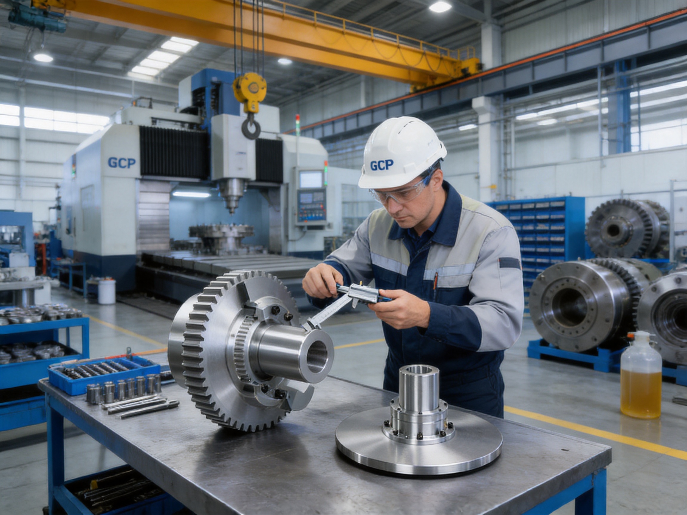
Modern heavy machinery demands more than simple torque transmission. In mining, metallurgy, lifting, conveying, marine, and process industries, drive systems must transfer large amounts of power, accommodate limited installation space, tolerate misalignment, operate reliably under severe loads, and stop rotating equipment safely when required. The GCP drum gear coupling with brake disc, manufactured according to Q/YG 13012X-2018, addresses these combined requirements through an integrated mechanical design that unites drum gear coupling technology and disc braking functionality in one compact assembly.
Unlike a conventional coupling that only connects two shafts, the GCP design also provides a prepared braking interface. The result is a coordinated transmission and stopping solution for industrial drives in which the coupling transfers torque during operation while the brake disc enables controlled deceleration, holding, and emergency stopping when paired with a suitable disc brake. This arrangement can reduce the number of separate components in a drive train, simplify layout planning, and improve the overall organization of the power transmission system.
The product range covers GCP1 through GCP14, with nominal torque ratings from 800 N·m to 180,000 N·m and allowable speeds up to 4,000 r/min, depending on the selected model. Brake disc diameters range from 315 mm to 1,000 mm. Multiple shaft-hole configurations, including Y, J1, and Z1 arrangements, enable the coupling to match different shaft diameters and connection requirements.
1. Product Concept and Industrial Role
A coupling is a critical part of any rotating machine. It joins the driving shaft to the driven shaft and transfers torque while helping the system manage installation tolerances and operating disturbances. In heavy equipment, the coupling is exposed to torsional loads, shock loads, vibration, temperature changes, contamination, and repeated acceleration and deceleration. If the coupling is undersized or poorly matched, the consequences may include excessive wear, gear tooth damage, overheating, unplanned stoppage, or failure of connected equipment.
The GCP drum gear coupling is intended for applications where high torque density and dependable mechanical transmission are essential. Its drum-shaped gear geometry allows the coupling to transmit substantial torque through multiple gear teeth while maintaining a relatively compact radial envelope. The design is particularly suitable for heavy machinery in which shaft misalignment may occur because of foundation movement, thermal expansion, bearing clearance, structural deflection, or installation tolerances.
The integrated brake disc changes the role of the coupling from a purely transmitting component into a multifunctional drive-train module. During normal operation, the gear coupling transfers torque between the two shafts. During stopping, an external brake caliper or compatible disc brake acts on the disc surface to produce braking torque. This makes it possible to position the braking function directly within the transmission path instead of installing a separate braking drum, brake wheel, or auxiliary shaft arrangement.
In applications such as hoists, cranes, conveyors, crushers, and winches, this arrangement can be valuable because the rotating system may need to stop quickly and predictably. A properly selected brake and coupling combination can help limit coasting, improve load positioning, support emergency shutdown procedures, and reduce the risk associated with uncontrolled rotation.
2. Main Advantages of the GCP Design
2.1 Integrated Power Transmission and Braking
The most visible advantage of the product is the integration of a drum gear coupling and brake disc. A conventional drive may require a separate flexible coupling, brake drum or disc, mounting hub, spacer, and additional support structure. Each extra component occupies space and introduces another interface that must be aligned, inspected, and maintained.
By incorporating the brake disc into the coupling assembly, the GCP system can reduce layout complexity. The braking surface is located in a known relationship to the coupling centerline, and the disc dimensions are selected as part of the coupling configuration. This can make equipment design more straightforward, particularly where the distance between the motor, gearbox, and driven machine is limited.
Integration also helps coordinate the mechanical functions. The coupling is designed to transmit torque and accommodate the intended operating conditions, while the disc provides a defined surface for the braking system. When the brake is correctly sized for the machine’s speed, inertia, stopping time, thermal duty, and load condition, the combined arrangement can deliver consistent stopping performance without requiring a separate transmission shaft for the brake.
2.2 High Torque Density
Drum gear couplings are recognized for their capacity to transmit high torque within a comparatively compact assembly. The GCP series extends this principle across fourteen sizes, allowing users to select a coupling according to nominal torque, shaft-hole diameter, speed, brake disc size, and installation dimensions.
The range begins with the GCP1, rated at 800 N·m, and progresses to the GCP14, rated at 180,000 N·m. This broad selection helps avoid the compromises associated with using one oversized coupling for several applications. A correctly matched size can provide the required load capacity while avoiding unnecessary mass, inertia, and installation space.
High torque density is especially useful in crushers, mixers, extruders, rolling-related equipment, mining conveyors, and lifting machinery. These applications may experience high starting torque, cyclic loading, reversing, impact loading, or frequent changes in operating conditions. The gear transmission structure distributes the torque across multiple teeth, helping the coupling handle the demands of heavy-duty service when properly lubricated and aligned.
2.3 Accommodation of Shaft Misalignment
Industrial shafts are rarely aligned perfectly under every operating condition. Static misalignment may arise during installation, while dynamic misalignment can be caused by bearing movement, shaft deflection, thermal expansion, and changing machine loads. A rigid connection transfers these deviations directly into the bearings and connected equipment, which may increase vibration and reduce service life.
The drum gear configuration permits a degree of angular and radial movement between the connected shafts. The external gear teeth and internal drum-shaped gear teeth engage while allowing the coupling to compensate for specified misalignment. This flexibility is one reason gear couplings are widely used in large industrial drive systems.
Misalignment capability should not be interpreted as permission to ignore alignment. The coupling must still be installed within the manufacturer’s permissible limits. Excessive misalignment can cause edge loading, accelerated tooth wear, lubricant loss, heat generation, and increased reaction forces. The practical advantage of the GCP design is that it can accommodate normal installation and operating deviations without imposing the restrictions of a fully rigid coupling.
2.4 Controlled Emergency Stopping
The brake disc gives the drive system a direct mechanical braking interface. When the brake receives a stop command, friction between the brake pads and disc produces a resisting torque. The rotating components then decelerate in a controlled manner until they stop or reach the required holding condition.
Stopping performance depends on the complete braking system rather than the coupling alone. Important factors include brake torque, machine inertia, operating speed, load direction, stopping frequency, pad friction characteristics, disc temperature, control response, and the selected safety factor. Nevertheless, a coupling with a correctly positioned and dimensioned brake disc provides a strong foundation for an effective braking arrangement.
In lifting equipment, braking is not only a convenience but also a major safety function. The brake may be required to hold a suspended load, stop a descending movement, or secure the mechanism during maintenance. In conveyors and material-handling equipment, controlled stopping can help prevent overshoot, reduce material spillage, and support emergency shutdown systems.
2.5 Compact Installation
Space is often limited around motors, reducers, shafts, and machine frames. A separate brake assembly may require an additional shaft extension, bearing support, guard, and mounting bracket. The GCP coupling offers a more consolidated arrangement by combining the coupling and brake disc in the same transmission region.
The cartridge-style brake disc structure is intended to facilitate installation and replacement. The disc dimensions, offset, and mounting features are calculated to correspond with different coupling sizes and disc brake arrangements. This can reduce the amount of custom fabrication needed during machine design, although the final brake clearance, support structure, guard, and service access must always be verified for the actual installation.
A compact layout can also reduce the length of the power train. Shorter shafts may have lower bending deflection and lower torsional compliance, while fewer support components can simplify inspection. The benefits are most pronounced when the equipment manufacturer plans the coupling and brake as one system from the beginning of the design process.
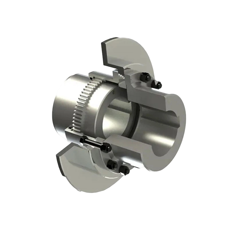
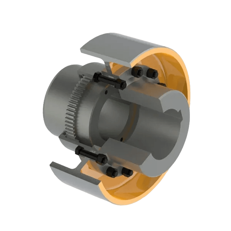
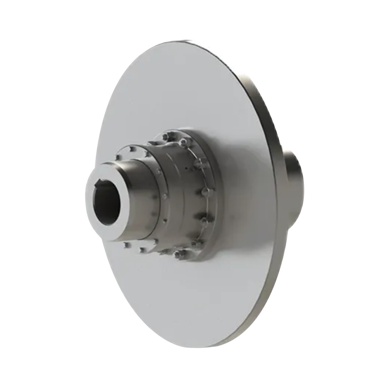
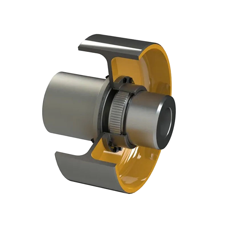
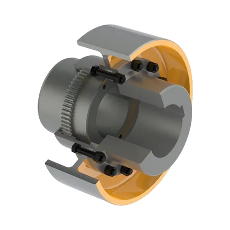
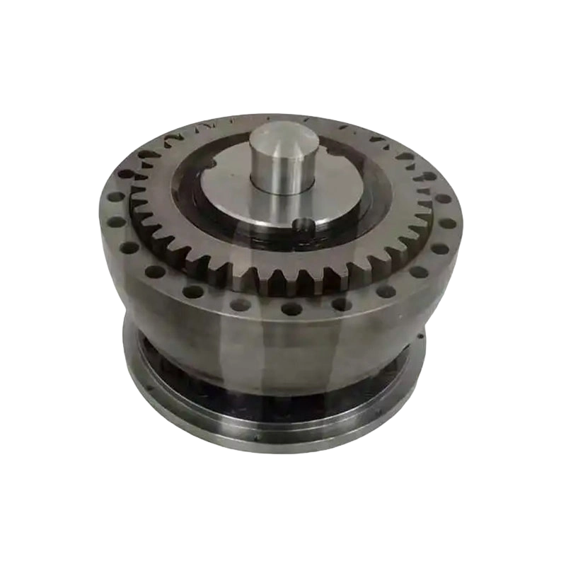
GCP Drum gear coupling with brake disc(Q/YG 13012X-2018)
3. Technical Range and Selection Data
The GCP series provides a graduated selection of coupling sizes. The following summary presents the principal nominal torque and speed ratings supplied for the series. These figures are general product ratings and must be checked against the actual load spectrum, service factor, shaft arrangement, brake duty, and operating environment.
| Model | Nominal Torque Tn | Allowable Speed | Typical Brake Disc Diameter Range | General Application Position |
|---|---|---|---|---|
| GCP1 | 800 N·m | 4,000 r/min | 315 mm and related configurations | Light to medium industrial drives |
| GCP2 | 1,400 N·m | 4,000 r/min | 315 mm and related configurations | Compact high-speed machinery |
| GCP3 | 2,900 N·m | 4,000 r/min | 355 mm and related configurations | Process and conveying equipment |
| GCP4 | 5,000 N·m | 3,000 r/min | 400–500 mm | Medium heavy-duty equipment |
| GCP5 | 8,000 N·m | 2,500 r/min | 400–500 mm | Mixers, conveyors, and process machinery |
| GCP6 | 11,200 N·m | 2,000 r/min | 450–630 mm | Mining and heavy material handling |
| GCP7 | 16,000 N·m | 1,700 r/min | 450–710 mm | Large conveyors and lifting systems |
| GCP8 | 22,400 N·m | 1,700 r/min | 500–710 mm | Large industrial drives |
| GCP9 | 28,000 N·m | 1,600 r/min | 560–800 mm | Heavy mining and processing machinery |
| GCP10 | 45,000 N·m | 1,600 r/min | 630–800 mm | Very heavy-duty transmission |
| GCP11 | 63,000 N·m | 1,400 r/min | 710–900 mm | Large lifting and conveying systems |
| GCP12 | 90,000 N·m | 1,400 r/min | 710–900 mm | High-capacity industrial machinery |
| GCP13 | 125,000 N·m | 1,400 r/min | 800–900 mm | Extreme-load applications |
| GCP14 | 180,000 N·m | 1,200 r/min | 900–1,000 mm | Largest heavy-duty drive systems |
The shaft-hole configurations include Y, J1, and Z1 types. Available shaft-hole diameters vary by model and configuration. Smaller sizes may accept shaft diameters in the range of approximately 12 mm to 56 mm, while the largest models can accommodate shaft diameters reaching approximately 260 mm in the listed configurations. For cone-shaft arrangements, the supplied technical notes specify a maximum shaft-hole diameter of 220 mm.
Brake disc diameters include 315, 355, 400, 450, 500, 560, 630, 710, 800, 900, and 1,000 mm. The disc table also identifies values such as disc thickness, installation-related dimensions, maximum shaft-hole diameter, mass, and moment of inertia for different structural groups. These values are important when calculating total rotor inertia, braking time, bearing loads, motor acceleration, and the energy absorbed during each stop.
For example, a 315 mm brake disc has a listed thickness of 15 mm and an approximate mass of 8.5 kg for one structural group and 6.7 kg for another. At the largest listed disc diameter of 1,000 mm, the thickness increases to 20 mm, while approximate masses rise to 128.8 kg and 115.1 kg for the respective groups. Such changes demonstrate why the brake disc must be included in the complete dynamic calculation rather than treated as an insignificant accessory.
4. How the Coupling Works During Operation
The GCP coupling contains two principal transmission sides connected through a drum gear arrangement. One side is attached to the driving shaft and the other to the driven shaft. The gear teeth engage with one another and transfer torque across the coupling. The geometry allows the shafts to operate with the specified degree of relative movement while maintaining torque transmission.
During normal operation, the motor or prime mover rotates the input half of the coupling. Torque flows through the gear teeth to the output half and then into the gearbox, drum, propeller shaft, conveyor pulley, crusher, or other driven machine. The coupling’s flexible gear engagement helps reduce the effects of small alignment deviations and supports smooth power flow.
Lubricant is essential because the gear teeth operate under high contact pressure and sliding conditions. The coupling includes a dedicated oil or grease injection port that allows lubrication service without complete disassembly of the main body. Maintaining the correct lubricant type, quantity, and replenishment interval is central to protecting the tooth surfaces and sealing system.
When a stop command is issued, the external disc brake clamps the brake disc. The friction force at the disc radius creates braking torque. The torque is transmitted through the coupling and connected shaft train, causing the rotating assembly to decelerate. If the brake is used for holding, the brake must be capable of maintaining the static load under the worst expected condition. If it is used for repeated dynamic stopping, thermal capacity and wear rate must be evaluated.
The coupling itself does not replace a complete safety control system. Emergency-stop circuits, brake release monitoring, overspeed protection, mechanical guards, load control logic, and inspection procedures remain necessary. The integrated disc simply makes it easier to incorporate an appropriate braking function into the mechanical drive.
5. Structural Design Features
5.1 Drum-Shaped Gear Geometry
The drum-shaped gear profile is designed to provide a broad and reliable engagement pattern while allowing angular movement. Compared with a rigid flange connection, this arrangement can reduce the transmission of alignment-related forces into the machine bearings. Compared with some smaller flexible couplings, the gear tooth structure offers a high torque capacity for demanding industrial applications.
The gear teeth must remain properly lubricated and protected from contamination. Dust, water, abrasive particles, and corrosive media can damage the tooth surfaces or degrade the lubricant. For outdoor, mining, marine, and dusty process applications, the coupling should be fitted with suitable seals, guards, and environmental protection as specified for the operating conditions.
5.2 Cartridge-Type Brake Disc
The cartridge-type brake disc structure helps organize the disc and coupling components into a coherent assembly. The disc thickness, offset, and mounting dimensions are calculated for compatibility with different models of disc brakes. This approach can reduce the need for field-made adapters and may improve the repeatability of brake installation.
The brake disc must be installed with the correct axial position and runout. Excessive runout may cause uneven pad clearance, vibration, noise, and unstable braking. The disc should also be protected from oil, grease, and other contaminants that could reduce friction. The coupling’s lubrication system must be maintained so that lubricant remains within the gear chamber and does not migrate onto the brake surfaces.
5.3 Maintenance Lubrication Port
A dedicated lubrication port is a practical feature for heavy industrial equipment. Large couplings may be difficult to remove because they are positioned between a motor and gearbox or inside a machine frame. If routine lubrication required major disassembly, maintenance time would increase and the likelihood of delayed service would become greater.
Through the lubrication port, service personnel can replenish the specified grease or lubricant according to the maintenance schedule. The port location should remain accessible after installation, and the guard should provide sufficient clearance for safe service. Lubricant inspection should include checking for metal particles, discoloration, water contamination, hardening, and abnormal odor, all of which may indicate gear or seal problems.
6. Advantages Compared with Alternative Coupling Arrangements
6.1 Compared with Rigid Couplings
Rigid couplings can provide a direct and simple connection, but they require accurate shaft alignment and do not compensate for operational displacement. When used in large machines, even a small alignment error can impose substantial additional loads on bearings and shafts.
The GCP coupling offers flexibility through gear engagement while maintaining a high torque rating. This makes it more suitable for equipment subject to thermal movement, foundation settlement, shaft deflection, or variable loading. The integrated brake disc is an additional advantage because a rigid coupling normally requires a separate braking arrangement.
6.2 Compared with Separate Coupling and Brake Systems
A drive system using a conventional coupling and a separately installed brake can be effective, but it may require more components and more installation space. Separate components also create additional alignment points and may require an extra shaft extension or support bearing.
The GCP arrangement consolidates these functions. The brake disc is designed as part of the coupling configuration, allowing the designer to select the disc diameter and coupling size together. This can simplify mechanical packaging and reduce the amount of custom connection work. The comparison is especially favorable in compact machinery and in retrofit projects where available space is restricted.
6.3 Compared with Non-Metallic Elastic Couplings
Non-metallic elastic couplings are often valued for vibration damping and reduced maintenance in light or medium applications. However, elastomeric elements may be sensitive to temperature, chemical exposure, aging, fatigue, and high shock loads. Their torque and speed capabilities may also be limited in comparison with large gear couplings.
The GCP uses a metallic gear transmission approach that is intended for high torque and severe industrial duty. It is therefore a strong candidate for machinery where compact torque transmission, high load capacity, and braking integration are more important than the damping characteristics of an elastomeric element. If the system requires substantial torsional vibration isolation, a detailed dynamic analysis should determine whether a gear coupling is appropriate or whether an additional damping element is needed.
6.4 Compared with Conventional Drum Couplings without Braking
A standard drum coupling can transmit torque and accommodate misalignment, but it does not inherently provide a braking surface. Adding a separate brake afterward may require redesigning the shaft, guard, or supporting frame. The GCP product is developed with brake disc dimensions and installation relationships already considered, which can reduce design uncertainty.
7. Applications in Heavy Industry
7.1 Crushers, Mixers, and Extruders
Crushers and large mixers often experience starting shocks, fluctuating resistance, and high torque demand. A coupling for this service must tolerate repeated load changes without excessive tooth wear or deformation. The GCP series provides a selection of torque ratings suitable for different machine sizes.
In a crusher, the brake disc can support controlled stopping after the crushing cycle or during an emergency. In mixers and extruders, the brake can help bring the rotating mass to a safe condition during maintenance or process interruption. The selected brake must be evaluated for the high inertia of the rotor, material load, and any stored torsional energy in the drive train.
7.2 Conveyors and Material Handling Systems
Long conveyors, bucket elevators, winches, and cranes require dependable drive transmission and controlled stopping. A conveyor may continue running for a significant period after the motor is switched off because of the inertia of the belt, pulleys, and conveyed material. The disc brake can shorten the stopping period when appropriately selected.
For lifting systems, the braking function may be used for positioning and load holding. The coupling’s flexibility helps accommodate shaft movement between the motor and gearbox, while the brake disc provides a practical location for the service or holding brake. Safety-critical lifting applications require redundant or fail-safe braking arrangements where applicable, and the coupling should be integrated into the overall risk assessment rather than considered in isolation.
7.3 Mining Equipment
Mining environments combine high torque, abrasive dust, vibration, outdoor exposure, and difficult maintenance access. Conveyors, crushers, excavators, and hoisting machinery may operate continuously under fluctuating loads. The GCP’s heavy-duty gear construction and accessible lubrication arrangement can be useful in these conditions.
Protection against contamination is essential. The coupling should use appropriate guards and seals, and the installation should prevent direct ingress of water and abrasive material. Maintenance teams should establish inspection intervals based on operating hours, load severity, ambient conditions, and the consequences of failure.
7.4 Marine and Propulsion Systems
Marine propulsion drives require careful consideration of corrosion, vibration, torsional resonance, alignment, and space. A coupling with integrated braking capability may be used where emergency stopping or shaft immobilization is required. The brake disc and coupling materials, coatings, seals, and lubrication must be selected for the marine environment.
Marine applications also require detailed torsional vibration analysis. The coupling’s stiffness, inertia, shaft-line arrangement, and engine firing characteristics should be considered together. The GCP product can provide a robust mechanical connection, but application approval and classification requirements must be evaluated for the specific vessel or marine installation.
7.5 Metallurgical and Port Equipment
Metallurgical equipment and port machinery frequently involve large motors, gearboxes, drums, cranes, and conveyors. These machines may need frequent starts and stops, accurate positioning, and resistance to shock loading. The broad GCP range allows selection from relatively compact units to couplings rated for very high torque.
In steel, port, and bulk-material facilities, airborne dust and elevated temperatures may affect lubricant life and brake performance. Proper guarding, ventilation, brake heat dissipation, and maintenance access should be included in the equipment design.
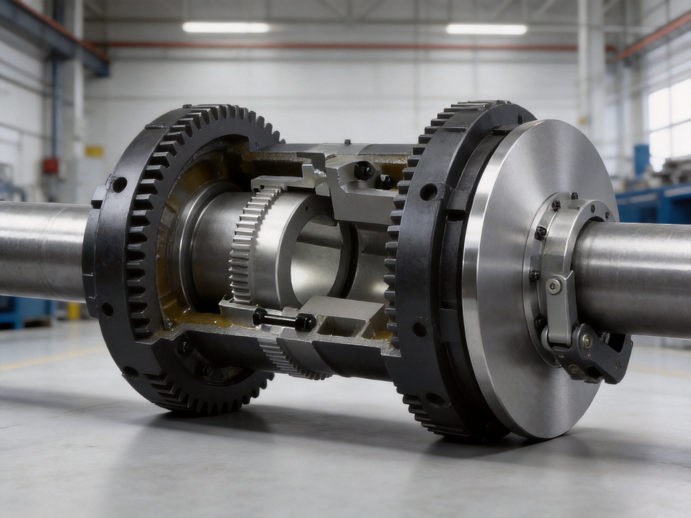
8. Manufacturing Strengths and Quality Advantages
The product is manufactured by Zhongye Heavy Industry Technology (Zhenjiang) Co., Ltd., a company that integrates research and development, manufacturing, and sales. This integrated structure is important for a product such as a drum gear coupling with brake disc because successful performance depends on coordinated design, material selection, machining accuracy, heat treatment, assembly, testing, and technical support.
The company operates a new workshop complex of approximately 16,463.52 square meters. The facility includes a heavy workshop of about 5,500 square meters, a precision workshop of approximately 4,600 square meters, an office building and gymnasium, a dining facility, a warehouse, and supporting roads and production areas. The separation of heavy and precision production areas provides a practical foundation for handling large coupling components while preserving the controlled conditions needed for accurate machining and assembly.
Large coupling components require appropriate lifting capability, stable machining equipment, and sufficient floor space. The heavy workshop supports the handling and processing of large hubs, gear sleeves, brake discs, and housings. The precision workshop is suited to dimensional control of gear profiles, bores, keyways, flange faces, sealing surfaces, and assembly interfaces.
8.1 Research and Development Capability
Research and development is particularly important when a product must serve many industries and load conditions. The company’s product portfolio includes toothed couplings, elastic sleeve pin couplings, elastic column pin couplings, gear couplings with elastic pins, universal couplings, tire couplings, jaw couplings, star couplings, diaphragm couplings, drum couplings, grid couplings, Oldham couplings, flange couplings, clamp-shell couplings, roller chain couplings, safety couplings, and non-standard coupling designs.
This broad range gives the engineering team experience with different transmission principles. It also allows the company to compare the advantages and limitations of gear, elastomeric, diaphragm, pin, chain, and rigid coupling technologies when recommending a solution. For customers with unusual shaft spacing, speed, torque, brake arrangement, or environmental requirements, this background supports more informed customization.
8.2 Material and Machining Control
A high-load coupling depends on the quality of its raw materials and the accuracy of its finished surfaces. Hubs and gear components must have sufficient strength and toughness to resist torsional stress, tooth contact pressure, impact, and fatigue. Brake discs must maintain dimensional stability and a suitable friction interface when paired with the selected brake.
Important manufacturing stages may include material verification, rough machining, stress relief, heat treatment where specified, finish machining, gear tooth generation, bore and keyway processing, surface inspection, cleaning, sealing installation, and final assembly. Dimensional inspection should cover critical diameters, concentricity, axial runout, gear tooth geometry, mounting faces, brake disc flatness, and shaft-hole tolerances.
For large parts, controlling deformation after heat treatment and during final machining is essential. A coupling may meet an individual dimensional requirement while still producing excessive vibration if concentricity or balance is not controlled. The production process should therefore consider the relationship between all rotating surfaces rather than inspecting each dimension independently.
8.3 Testing and Quality Assurance
The company states that it maintains advanced testing facilities and strict quality control. For drum gear couplings, quality assurance may include inspection of material certificates, dimensional checks, gear tooth contact assessment, runout measurement, balance verification where required, lubricant and seal inspection, and functional assembly checks.
Brake disc quality control should include disc diameter, thickness, axial runout, mounting-hole position, surface condition, and compatibility with the specified brake. The coupling and disc must remain correctly aligned after assembly. Inspection records help provide traceability and support service investigations if operating conditions change.
Compliance with ISO 9001-related quality management practices provides a framework for consistent production, documentation, corrective action, and process improvement. Actual certification scope and project-specific inspection requirements should be confirmed during the purchasing and technical approval process.
8.4 Custom Manufacturing and Non-Standard Solutions
Industrial drive systems do not always conform to standard catalogs. Customers may require a special shaft-hole combination, unusual keyway, modified brake disc diameter, altered hub length, special coating, different sealing arrangement, or adaptation to an existing gearbox and motor.
The company undertakes the design and manufacture of non-standard couplings. This capability can be valuable during equipment upgrades and replacement projects, where the existing foundation and shaft dimensions cannot easily be changed. A custom solution should be developed from complete technical information, including torque, speed, shaft dimensions, key details, misalignment, ambient conditions, duty cycle, braking requirements, and installation drawings.
Customization should not be limited to changing a bore diameter. The effect of any modification on tooth strength, balance, shaft stress, disc inertia, brake clearance, lubrication access, and guard dimensions must be assessed. An experienced manufacturer can help ensure that the customized component remains mechanically coherent.
9. Engineering Selection Procedure
Selecting the correct GCP coupling begins with determining the transmitted torque. The nominal torque should not be based solely on the motor’s rated power. Starting torque, overload, reversing, impact, cyclic operation, and driven-machine resistance must be included. A typical calculation begins with power and speed:
T = 9550 × P / n
In this expression, T is torque in N·m, P is power in kW, and n is rotational speed in r/min. The calculated torque is then multiplied by suitable service factors for the machine type and duty. The resulting design torque should be compared with the coupling’s nominal torque rating.
For example, a drive transmitting 500 kW at 1,000 r/min has a theoretical operating torque of approximately 4,775 N·m before service factors. If the application involves impact loading and frequent starts, the selected coupling may need to be considerably larger than the basic calculated value. The designer must also check the allowable speed, shaft-hole capacity, and brake disc arrangement.
The next step is to confirm the shafts. Record the shaft diameters, keyway dimensions, available shaft lengths, hub length, shaft extension, and any taper or cone details. The selected Y, J1, or Z1 shaft-hole configuration must match the actual shaft connection. The available shaft-hole length L is also important because a coupling cannot be safely installed if the shaft engagement is insufficient.
Misalignment should then be evaluated. Determine the expected angular, parallel, and axial movement under both static and operating conditions. These values should remain within the manufacturer’s permissible limits. If the machine has large thermal movement or significant shaft deflection, a detailed alignment study may be necessary.
The brake selection must be performed in parallel. Required braking torque depends on the resisting torque of the machine, the desired deceleration, the total reflected inertia, and whether the brake must hold a static load. For a rotating system, braking energy increases with the square of speed. Repeated high-speed stops may produce significant heat, so the brake disc diameter, pad material, cooling conditions, and duty cycle must be reviewed.
The brake disc’s mass and moment of inertia should be added to the machine inertia calculation. The supplied disc data show that inertia rises substantially as diameter increases. The designer must also include the inertia of hubs, shafts, couplings, gearboxes, drums, pulleys, and connected loads.
Finally, check the installation envelope. Confirm overall dimensions such as D, D2, D4, B, F, N, and the various C dimensions. Since some dimensions vary with brake disc diameter, the exact selected disc must be identified before the foundation, guard, brake bracket, and shaft spacing are finalized.
10. Installation Recommendations
Before installation, inspect the coupling, shaft ends, keyways, brake disc, seals, fasteners, and lubrication ports. Remove protective coatings only where necessary and ensure that no abrasive material enters the gear chamber. Shaft surfaces should be clean, free of burrs, and within the specified dimensional tolerances.
Check the shaft alignment using suitable measurement equipment. Depending on the machine size and accuracy requirements, this may include dial indicators, laser alignment tools, straightedges, or precision measuring instruments. Alignment should be checked in the final operating position, with the motor, gearbox, and driven equipment secured to their foundations.
Install the coupling halves according to the approved drawing. Do not force a hub onto a shaft by hammering, as impact can damage bearings, seals, gear components, or the brake disc. If heating is required for an interference fit, control the temperature carefully and protect seals and finished surfaces.
Verify that the brake disc is centered in the brake caliper and that the specified pad clearance is maintained around the complete rotation. Rotate the shaft manually where possible to check for interference, uneven clearance, abnormal runout, or contact with guards. The brake disc must remain free of grease and oil.
After installation, fill the coupling with the specified lubricant. Do not substitute an incompatible grease or overfill the chamber. Excess lubricant can increase churning losses and operating temperature, while insufficient lubricant can accelerate gear wear. Fit all plugs and seals securely after lubrication.
Install guards around the rotating coupling and brake disc. The guard should prevent accidental contact while permitting inspection and service access. It should not interfere with disc cooling or create a path for lubricant to reach the brake pads. Before commissioning, check all fasteners, foundation bolts, brake supports, electrical interlocks, and emergency-stop functions.
11. Maintenance and Service Life
Routine maintenance should include visual inspection, lubrication, fastener checks, alignment verification, brake inspection, and monitoring for abnormal noise or temperature. The inspection frequency should reflect the severity of service. A continuously operating mining conveyor requires a different schedule from an intermittently used process machine.
Abnormal rattling, clicking, knocking, or rising vibration may indicate gear tooth wear, insufficient lubrication, excessive misalignment, looseness, or damage. A temperature increase around the coupling may result from lubricant problems, seal friction, overload, or gear contact conditions. Any unusual symptom should be investigated before continued operation causes secondary damage.
Lubricant should be replenished at the recommended interval. During scheduled shutdowns, inspect the condition of the lubricant and examine accessible sealing areas. If metal particles appear in the grease, the coupling should be opened for a more detailed inspection. Gear teeth should be checked for pitting, scoring, spalling, cracks, plastic deformation, and abnormal wear patterns.
The brake disc should be inspected for cracks, excessive wear, heat checking, distortion, corrosion, and oil contamination. Brake pads should be checked for remaining thickness and even contact. Uneven pad wear may indicate misalignment between the caliper and disc or excessive disc runout.
Replacement parts should match the original material, dimensions, hardness, sealing arrangement, and performance requirements. Mixing components from different coupling sizes or modifying the disc without engineering approval can compromise torque capacity and braking safety. Maintenance records should document lubrication, inspections, brake adjustments, replacement parts, and any operating incidents.
12. Safety Considerations
The GCP coupling and brake disc are rotating components and must be guarded during operation. Installation, inspection, lubrication, and repair should be performed only after the machine has been shut down, isolated from all energy sources, and secured against unexpected movement.
For lifting and suspended-load equipment, the coupling brake must not be assumed to be the only protective measure unless the complete system has been designed and approved for that purpose. Fail-safe brake release, redundant holding, load monitoring, emergency power behavior, and mechanical restraint may be required depending on the application and applicable regulations.
Brake testing should be performed under controlled conditions. Confirm that the brake releases completely during operation and applies reliably during a stop command. A brake that drags continuously may overheat the disc and increase energy consumption, while a brake that applies too slowly may fail to meet the required stopping distance.
Operators should be trained to recognize abnormal vibration, noise, brake smell, smoke, oil leakage, and unusual stopping behavior. A clear inspection and emergency-response procedure reduces the likelihood that an early warning will be ignored.
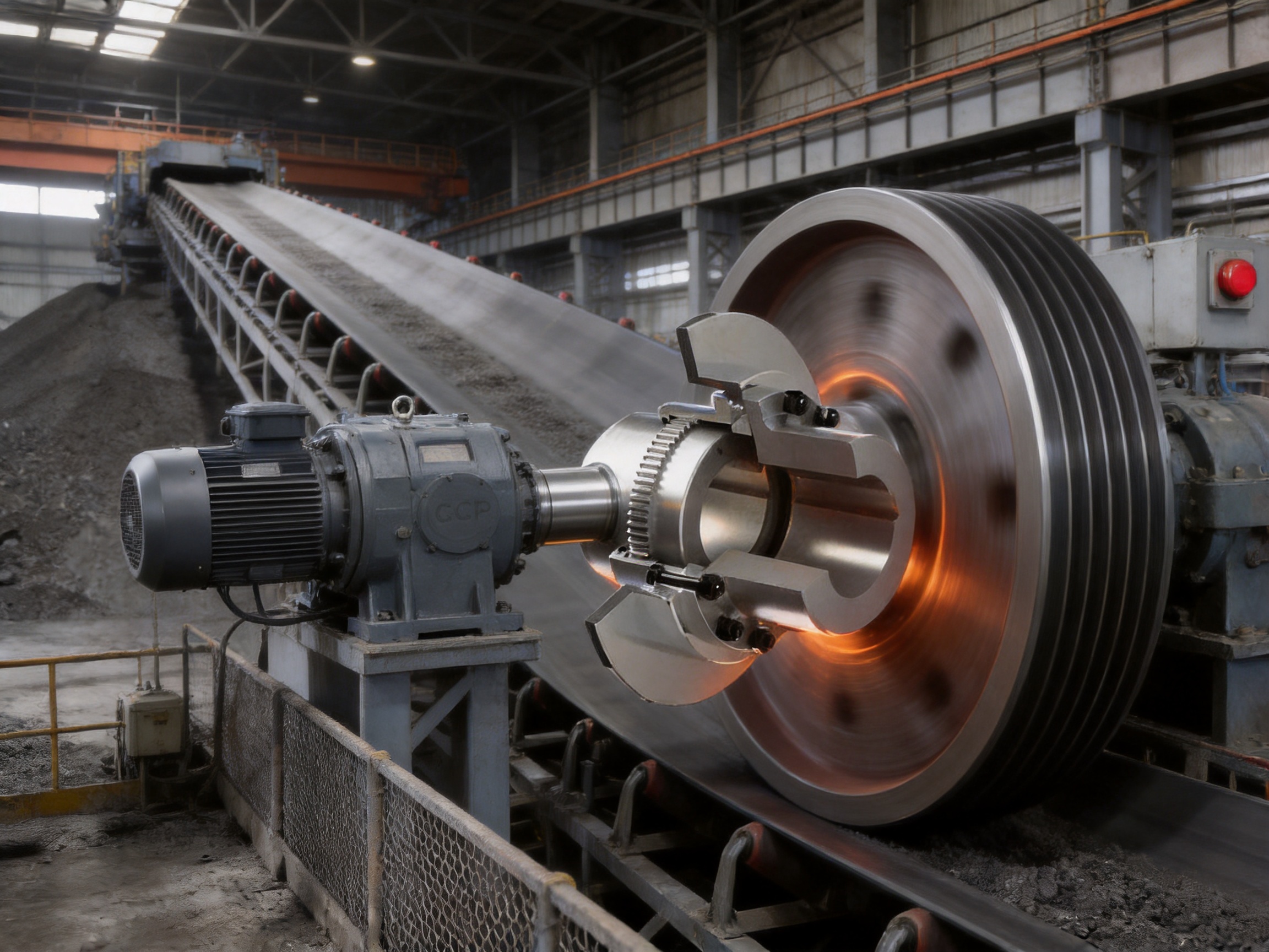
13. Why the Product Is Suitable for International Industrial Projects
International equipment projects often involve different machine builders, installation contractors, standards, and environmental conditions. A coupling supplier must therefore provide more than a standard part number. The supplier should support technical selection, drawing confirmation, dimensional coordination, production, inspection, packaging, and after-sales communication.
The GCP series offers a structured product family with fourteen torque sizes and multiple shaft-hole and brake-disc options. This makes it easier to establish a standard selection method across different machine platforms. The published technical data include nominal torque, speed, shaft-hole diameters, shaft-hole length, principal external dimensions, mass, inertia, and grease quantity. Such information supports early layout and dynamic calculations.
The manufacturer’s experience across metallurgical, mining, water, lifting, paper, port, and general industrial equipment provides a broad application background. This is useful when a customer’s machine combines several challenges, such as high torque, limited space, frequent braking, dust exposure, and non-standard shaft dimensions.
Technical support before purchase can help identify the correct model and prevent common errors such as selecting a coupling only by motor power, overlooking brake inertia, failing to check shaft-hole length, or placing the brake disc outside the permitted installation envelope. After-sales support can assist with installation questions, lubrication practices, replacement components, and troubleshooting.
14. Practical Comparison of Product Benefits
| Evaluation Item | GCP Drum Gear Coupling with Brake Disc | Separate Rigid Coupling and Brake | Small Elastomeric Coupling with External Brake |
|---|---|---|---|
| Torque capacity | Broad range up to 180,000 N·m | Potentially high, depending on separate components | Usually more limited for very heavy loads |
| Misalignment tolerance | Gear-based flexibility within specified limits | Low for rigid coupling | Good for selected light and medium duties |
| Brake integration | Brake disc designed into coupling arrangement | Requires separate brake installation | Usually requires separate brake installation |
| Installation space | Consolidated transmission and braking layout | May require additional shaft and support space | May require additional components |
| High-temperature or severe-duty suitability | Suitable when material, lubricant, seals, and brake are properly selected | Depends on each component | Elastomer may require special evaluation |
| Maintenance focus | Gear lubrication, seals, alignment, disc, and brake pads | Separate maintenance for coupling and brake | Elastic element inspection plus brake maintenance |
| Customization potential | Multiple shaft-hole and disc options, plus non-standard design capability | Depends on several suppliers and interfaces | Often limited by elastic element size and geometry |
This comparison does not mean that one coupling type is correct for every machine. Elastomeric couplings may be preferable where vibration damping is the primary requirement, and rigid couplings may be appropriate for accurately aligned shaft systems without relative movement. The GCP product is most advantageous where high torque, heavy-duty operation, shaft flexibility, compact installation, and integrated braking are required together.
15. Customer Support and Supply Capability
Zhongye Heavy Industry Technology (Zhenjiang) Co., Ltd. provides coupling design, manufacturing, sales, and technical support from its facility in Zhenjiang, Jiangsu Province, China. The company’s product portfolio and manufacturing infrastructure support both standard product supply and customized engineering projects.
For technical inquiries, customers should provide the motor power, speed, operating torque, peak torque, machine type, duty cycle, shaft diameters, keyway or taper details, shaft spacing, expected misalignment, brake torque, brake disc diameter, ambient temperature, contamination level, and required certification. Supplying this information at the beginning allows the manufacturer to make a more accurate recommendation and prepare the correct dimensional drawing.
The company can be contacted through its sales department by telephone, email, or WhatsApp. Its customer-service model includes pre-sale technical assistance, non-standard design support, production coordination, quality control, delivery support, and after-sale service. The combination of engineering and manufacturing capability is particularly useful for customers who need a coupling matched to an existing machine rather than a generic catalog item.
16. Frequently Asked Questions
Q1: What is the primary purpose of the GCP drum gear coupling with brake disc?
The product transfers torque between two shafts while providing an integrated disc surface for a compatible braking system. It is intended for heavy industrial drives that require both flexible transmission and controlled stopping.
Q2: What standard is associated with this product?
The product is identified according to Q/YG 13012X-2018. The purchaser should confirm the required technical edition, drawings, inspection documents, and project standards before ordering.
Q3: What is the torque range of the GCP series?
The listed range extends from 800 N·m for GCP1 to 180,000 N·m for GCP14. The correct selection depends on calculated operating torque, service factor, peak load, speed, shaft size, and duty cycle.
Q4: What is the maximum allowable speed?
The highest listed allowable speed is 4,000 r/min for selected smaller models. Allowable speed decreases as coupling size and torque capacity increase, with the largest GCP14 model listed at 1,200 r/min. The selected model must not exceed its specified speed.
Q5: What brake disc diameters are available?
The listed brake disc diameters range from 315 mm to 1,000 mm. Not every disc diameter is available for every coupling model, so the final combination must be confirmed from the dimensional table and application drawing.
Q6: Can the coupling compensate for shaft misalignment?
Yes. The drum gear structure permits specified angular and radial movement between the shafts. However, the coupling is not a substitute for proper alignment, and actual misalignment must remain within the manufacturer’s allowable values.
Q7: Does the coupling include the complete braking system?
The product includes the coupling with brake disc. A compatible disc brake, caliper, control system, support bracket, hydraulic or electrical actuation system, and safety controls must be selected separately unless specifically included in the quotation.
Q8: How is the coupling lubricated?
The coupling uses a dedicated lubrication port for maintenance. The specified grease or lubricant should be used in the correct quantity and replenished according to the operating conditions and maintenance schedule.
Q9: Can the product be customized?
Customization may be available for shaft-hole dimensions, keyways, installation dimensions, brake disc arrangements, materials, seals, coatings, and other non-standard requirements. Any modification should be reviewed for torque capacity, balance, braking compatibility, and structural safety.
Q10: What information is needed for model selection?
Important information includes motor power, operating speed, calculated torque, peak torque, machine type, service factor, shaft diameters, shaft lengths, keyway details, shaft spacing, misalignment, brake torque, stopping time, brake duty cycle, ambient conditions, and required standards.
Q11: Is the product suitable for mining equipment?
It is designed for heavy industrial service and can be considered for mining conveyors, crushers, excavators, and related machinery. Mining installations require suitable sealing, guarding, lubrication, corrosion protection, and maintenance planning.
Q12: Why is brake disc inertia important?
The brake disc adds rotating mass to the system. Its moment of inertia affects acceleration, deceleration, brake energy, stopping time, and thermal load. As disc diameter increases, inertia can rise significantly, so it must be included in the complete dynamic calculation.
Q13: Can the brake disc be used to hold a suspended load?
It may be used as part of a properly designed holding-brake system, but the complete lifting application must be assessed for static load, emergency conditions, redundancy, fail-safe operation, and applicable safety requirements. The coupling alone should not be treated as a complete lifting safety system.
Q14: What are the main maintenance concerns?
The main concerns are correct lubrication, gear tooth condition, seal integrity, shaft alignment, fastener security, brake disc runout, brake pad wear, contamination, abnormal temperature, and vibration. Regular inspection helps identify problems before they become failures.
Q15: What makes this product different from a standard gear coupling?
The defining difference is the integrated brake disc. The product retains the high-torque and misalignment capabilities of a drum gear coupling while providing a prepared mechanical interface for controlled braking and emergency stopping.
17. Conclusion
The GCP drum gear coupling with brake disc is a specialized solution for industrial power transmission systems that require high torque capacity, flexible shaft connection, compact installation, and dependable braking integration. Its fourteen-model range covers nominal torque ratings from 800 N·m to 180,000 N·m, while multiple shaft-hole configurations and brake disc diameters support a wide variety of machinery.
The product’s main engineering advantages include the high torque density of drum gear transmission, the ability to accommodate specified shaft misalignment, the integration of a cartridge-style brake disc, accessible lubrication, and compatibility with heavy-duty applications. These features can reduce layout complexity compared with separate coupling and brake arrangements, while offering a more robust alternative to smaller elastic couplings in demanding environments.
Its performance depends on correct engineering selection, accurate installation, proper lubrication, reliable braking-system design, and disciplined maintenance. Torque, speed, shaft dimensions, misalignment, brake energy, disc inertia, thermal duty, and environmental conditions must all be considered before final approval.
Supported by research and development, heavy and precision manufacturing workshops, quality-control procedures, customization capability, and experience across many industrial sectors, Zhongye Heavy Industry Technology (Zhenjiang) Co., Ltd. is positioned to supply both standard and engineered coupling solutions. For customers seeking an integrated transmission and braking component for mining, metallurgy, lifting, conveying, marine, process, or port equipment, the GCP series provides a practical and scalable foundation for a reliable drive system.
References
1. Q/YG 13012X-2018, Technical Standard for GCP Drum Gear Couplings with Brake Disc.
2. GCP Drum Gear Coupling with Brake Disc Product Data, Basic Parameters and Main Dimensions.
3. GCP Brake Disc Main Size, Mass, and Moment of Inertia Data.
4. ISO 9001, Quality Management Systems—Requirements.
5. General engineering principles for industrial gear coupling selection, lubrication, alignment, and maintenance.
6. General engineering principles for industrial disc brake torque, thermal capacity, stopping energy, and safety assessment.
Product: GCP Drum gear coupling with brake disc(Q/YG 13012X-2018)
- Quick Links
- About
- Products
- Our Service
- News & Events
- Contact
- Products Series
- Flexible Couplings with Non-Elastic Elements
- Flexible Couplings with Metal Elastic Elements
- Flexible Couplings with Non-Metallic Elastic Elements
- Safety Coupling
- Rigid Coupling
- Contact Us
- Tel : +86 511 8572 3800 +86 511 8572 3900
- Mobile : +86 15106109009
- Email : sales@couplingzy.com
- Add:No.1 Zhongye Yingbin Avenue, Gaozi Street, Dantu Economic Development Zone, Zhenjiang City, Jiangsu Province, China.


