:+86 15106109009
:sales@couplingzy.com


 English
  русский
  Español
  عربى
عربى  Português
  Deutsch
  Türk
Türk  Indonesia

GBD Motor Shaft Extension Drum Gear Coupling: Design, Performance, and Industrial Applications
Content
- 1 1. Product Overview
- 2 2. Operating Principle of the Drum Gear Structure
- 3 3. Principal Technical Advantages
- 4 4. Series Range and Technical Parameters
- 5 5. Manufacturing Process and Quality Control
- 6 6. Advantages Compared with Alternative Coupling Types
- 7 7. Applications in Heavy Industry
- 8 8. Installation Guidelines
- 9 9. Maintenance and Service Practices
- 10 10. Product Selection Procedure
- 11 11. Company Manufacturing and Service Strengths
- 12 12. Reliability, Cost Efficiency, and Lifecycle Value
- 13 13. Frequently Asked Questions
- 13.1 What type of coupling is the GBD series?
- 13.2 What is the main purpose of the coupling?
- 13.3 What torque range does the GBD series cover?
- 13.4 What is the maximum allowable speed?
- 13.5 What shaft diameters are available?
- 13.6 Does the coupling require lubrication?
- 13.7 Can the coupling compensate for serious shaft misalignment?
- 13.8 Is the GBD coupling suitable for high-temperature applications?
- 13.9 Where is the coupling commonly used?
- 13.10 Can customized couplings be manufactured?
- 13.11 What should be checked before ordering?
- 13.12 How can abnormal coupling noise be investigated?
- 14 14. Conclusion
- 15 References
- 16 Product: GBD Motor shaft extension drum gear coupling(Q/YG 11003X-2018)
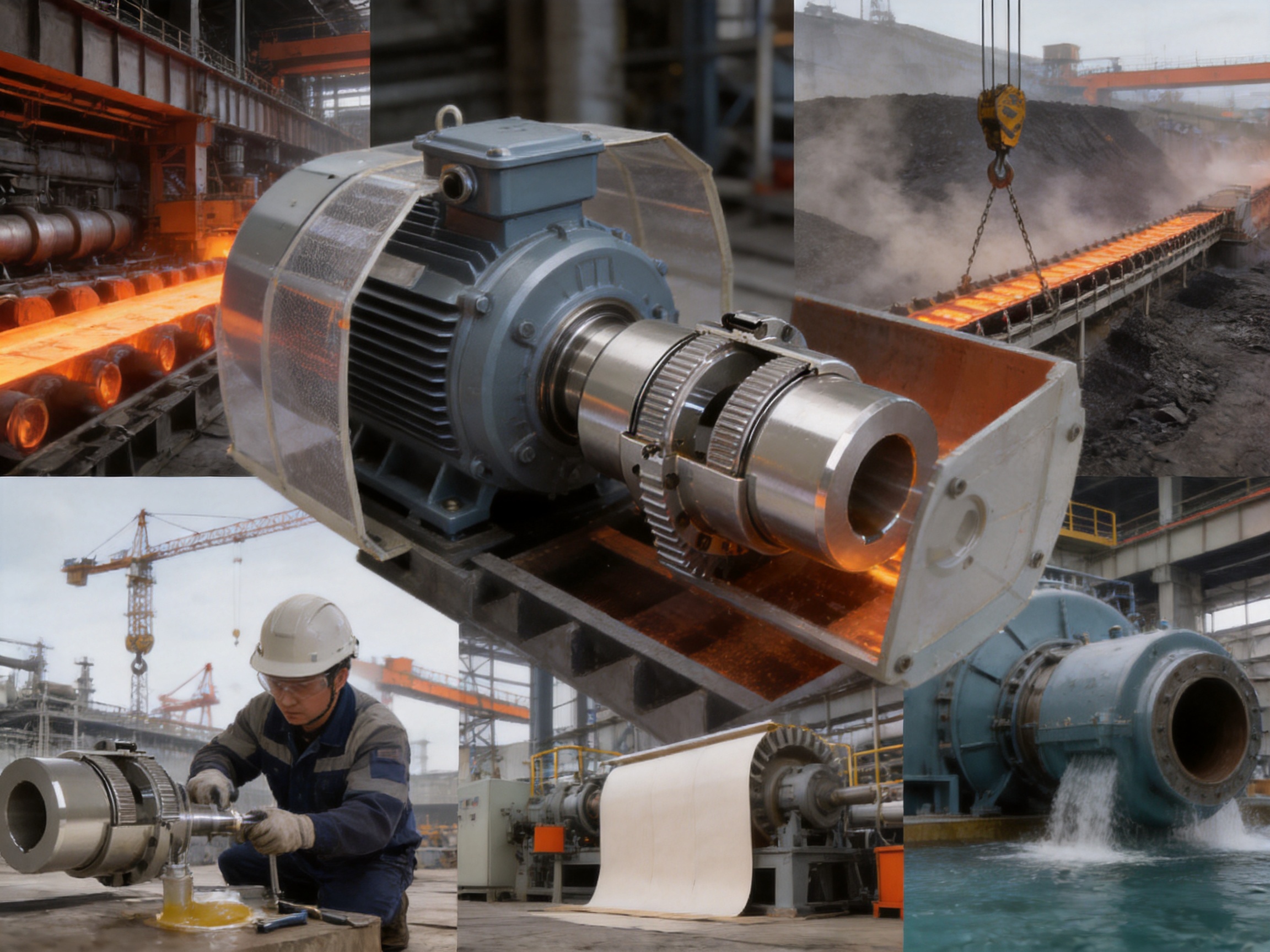
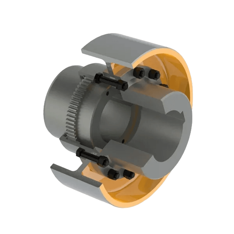
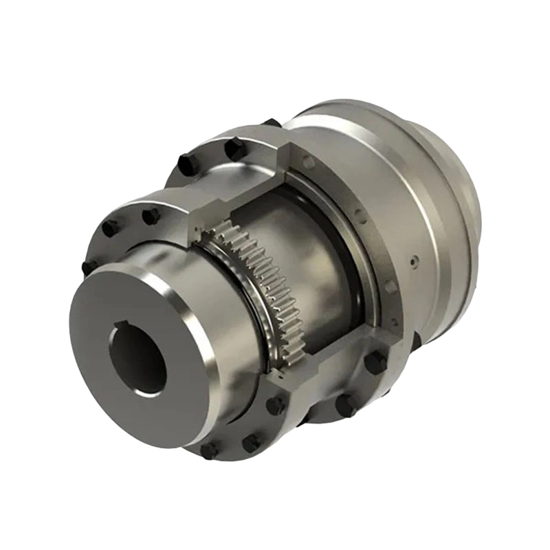
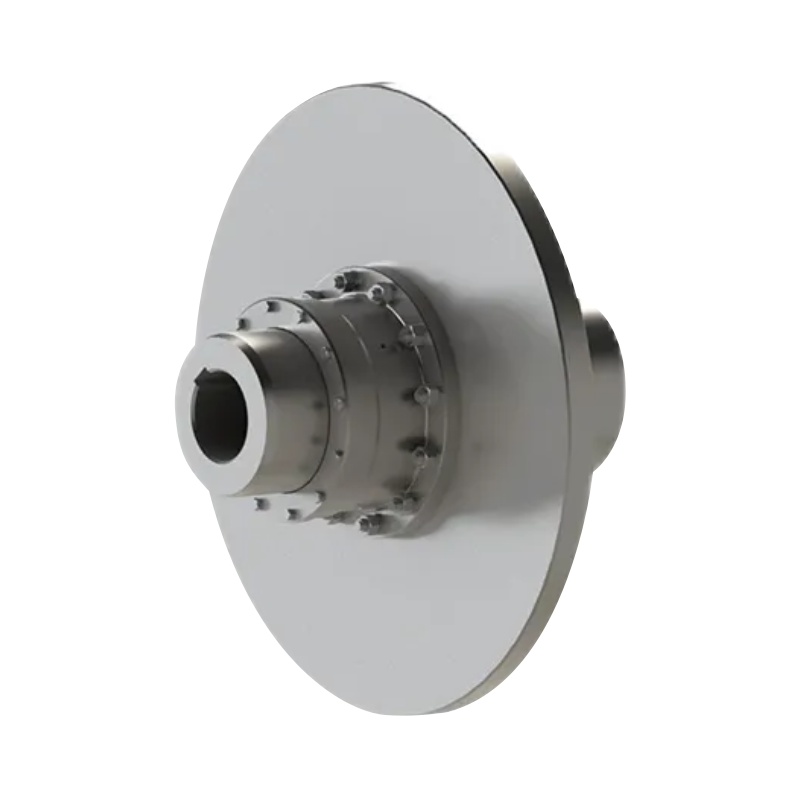
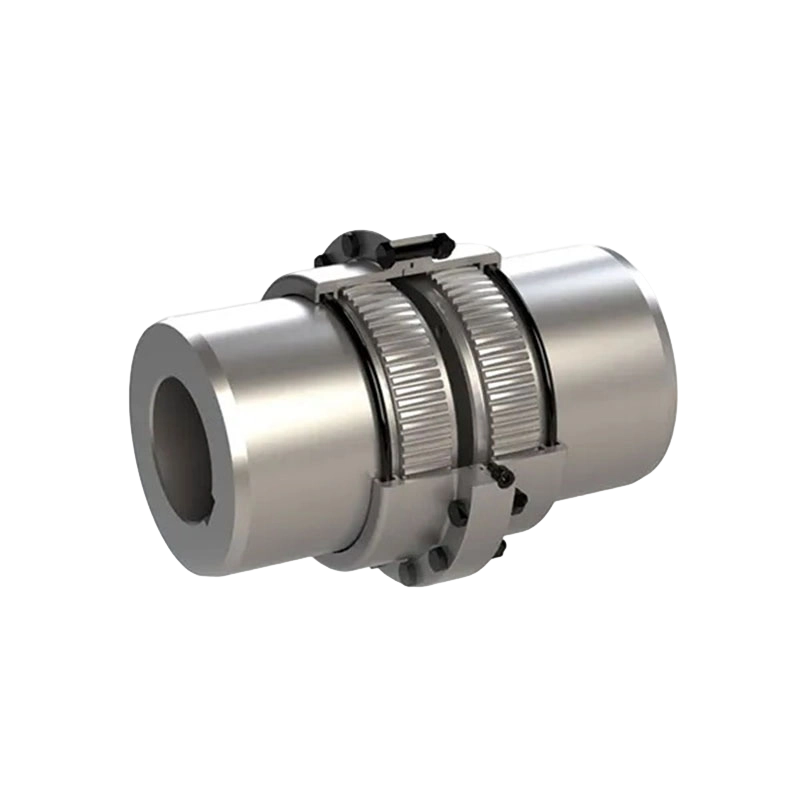
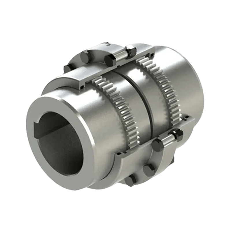
The GBD motor shaft extension drum gear coupling is a heavy-duty power transmission component developed for industrial machinery that requires dependable torque transfer, misalignment compensation, compact construction, and long operating life. Manufactured in accordance with the Q/YG 11003X-2018 enterprise standard, the GBD series is designed to connect a motor shaft with driven equipment while maintaining stable mechanical transmission under demanding operating conditions.
Unlike a rigid coupling, which requires highly accurate shaft alignment, the GBD coupling uses a drum-gear structure to accommodate axial, radial, and angular displacement between connected shafts. This capability makes it suitable for equipment exposed to shaft deflection, installation tolerances, foundation movement, thermal expansion, shock loads, and changing operating conditions.
The series includes ten main sizes, from GBD1 through GBD10. Nominal torque ratings range from 1.6 kilonewton-metres to 56 kilonewton-metres, while allowable speed ratings extend from 2,450 revolutions per minute to 5,600 revolutions per minute depending on the model. Bore combinations cover shaft diameters from approximately 22 millimetres to 200 millimetres, allowing the coupling to serve both compact drive systems and large industrial machines.
Its application range includes metallurgical equipment, mining machinery, lifting and conveying systems, port machinery, hydraulic engineering equipment, papermaking machinery, and other high-load industrial drive systems. The coupling is especially valuable where transmission reliability, compact installation, and reduced maintenance downtime are essential.
1. Product Overview
A coupling is responsible for transferring torque from one shaft to another while accommodating the practical imperfections that exist in real mechanical systems. Even when shafts are carefully positioned during installation, some degree of misalignment may occur during operation. Bearings can wear, foundations can settle, shafts can deflect under load, and connected machines can expand at different rates as temperatures change.
The GBD motor shaft extension drum gear coupling is designed for these conditions. Its principal transmission elements are a pair of toothed components and an external drum-shaped sleeve. The gear teeth engage to transmit torque, while the tooth geometry permits controlled movement between the connected shafts. The housing and sleeve arrangement provides an enclosed transmission path and supports the retention of lubricant around the working tooth surfaces.
The motor shaft extension arrangement is particularly useful for drive systems in which the motor shaft must connect to a gearbox, drum, roller, pump, conveyor, hoist, or other driven machine through a relatively compact coupling assembly. The design avoids the need for a large flexible element made from rubber or polymer and instead relies on precision-machined metal gear components for torque transmission and movement compensation.
The coupling is categorized as a flexible coupling with non-elastic elements. This means that it does not depend on an elastomeric insert, rubber tire, polymer spider, or metallic spring element to provide flexibility. Its flexibility is generated by the controlled interaction of the gear teeth and the geometry of the connected components.
This construction gives the GBD series several important characteristics. It can transmit high torque in relation to its overall size, operate in heavy industrial environments, withstand repeated load changes, and accommodate certain alignment errors without the rapid deterioration that can occur in some elastic couplings. At the same time, the coupling requires suitable lubrication and correct installation to achieve its designed service life.
2. Operating Principle of the Drum Gear Structure
The operating principle of the GBD coupling is based on external and internal gear engagement. One shaft is connected to a toothed hub or gear component, while the other shaft is connected to the mating gear element. The surrounding sleeve engages with the gear teeth and provides the structural connection between the two sides of the coupling.
When the motor rotates, torque passes through the shaft-mounted gear element and into the mating gear teeth. Because the teeth are distributed around the circumference, the transmitted load is shared by many tooth flanks rather than concentrated at one flexible insert or a small number of pins. This distribution supports high torque transmission and helps the coupling withstand changing loads.
The drum-shaped tooth profile is central to the coupling’s flexibility. Compared with a straight-sided gear arrangement, the crowned or drum-shaped tooth form allows the mating components to move slightly in angular and radial directions while maintaining effective contact. This reduces the risk of edge loading when the connected shafts are not perfectly coaxial.
Axial movement can also be accommodated within the allowable design range. This is important in drive systems where shafts move because of thermal expansion, bearing clearance, structural deflection, or changes in the position of connected equipment. The coupling does not eliminate the need for alignment, but it provides a practical tolerance for operating movement.
The gear teeth must remain properly lubricated because the coupling transmits substantial mechanical force through sliding and rolling contact. The GBD design includes an internal lubricant reservoir. The specified grease quantity varies by model, from approximately 107 millilitres for the smallest size to 1,320 millilitres for the largest size listed in the technical data.
A properly sealed and lubricated gear coupling can reduce tooth wear, lower friction, limit heat generation, and protect the working surfaces against contamination. For this reason, lubrication is not an optional accessory; it is a fundamental part of the coupling’s performance and maintenance requirements.
3. Principal Technical Advantages
3.1 High Torque Capacity in a Compact Form
One of the main advantages of a drum gear coupling is its high torque density. The GBD series reaches a nominal torque of 56 kilonewton-metres in the GBD10 model while maintaining a relatively compact radial profile compared with many alternative high-torque connection systems.
High torque density is valuable where installation space is restricted. A coupling that can transmit more torque without excessive outside diameter can simplify machine design, reduce the size of protective guards, and make it easier to position the motor and driven machine near one another.
The compact construction also benefits equipment manufacturers that need to keep the overall drive train short. A shorter transmission arrangement can reduce shaft overhang, limit bending moments, and improve the stiffness of the mechanical assembly.
3.2 Compensation for Multiple Types of Misalignment
The GBD coupling is designed to compensate for axial, radial, and angular misalignment within its permissible operating limits. These three forms of movement occur for different reasons and can have different effects on a drive system.
Axial misalignment refers to movement along the shaft axis. It may result from thermal expansion, bearing displacement, shaft movement, or changes in the position of connected machines. Radial misalignment occurs when the shaft centerlines are parallel but offset. Angular misalignment occurs when the shaft centerlines meet at an angle rather than remaining parallel.
In practical equipment, these conditions often occur together. A coupling that accommodates only one form of movement may still impose excessive forces on bearings or connected shafts. The GBD design offers a more comprehensive compensation capability than a rigid flange coupling and provides a heavy-duty alternative to some elastic couplings where high temperature, oil exposure, or severe shock loading makes elastomeric components less desirable.
Misalignment compensation must not be interpreted as permission to ignore installation accuracy. Excessive misalignment can overload the teeth, increase heat generation, accelerate lubricant degradation, and shorten the service life of the coupling and connected bearings. The coupling is intended to manage normal operational movement, not correct major assembly errors.
3.3 Resistance to Shock and Load Variation
Industrial machines rarely operate under perfectly steady loads. Cranes, conveyors, rolling mills, crushers, hoists, pumps, and paper machinery may experience starting torque, stopping torque, impact loads, reversing cycles, material surges, or sudden changes in resistance.
The metal gear transmission path of the GBD coupling is well suited to these conditions. The strong gear teeth can handle substantial torque fluctuations, while the flexible engagement helps prevent alignment errors from being transferred directly into the motor bearings and driven machine bearings.
The coupling can also help moderate vibration generated by the drive system. It does not function as a dedicated elastomeric vibration isolator, but its flexible gear engagement and structural mass can reduce the harmful effects of small alignment changes and transient mechanical disturbances.
For severe applications, the correct coupling size should be selected using the actual operating torque, starting conditions, duty cycle, service factor, speed, shaft dimensions, and environmental conditions. Nominal torque is a fundamental reference value, but it should not be treated as the only selection criterion.
3.4 Durable Metal Construction
The GBD series uses a robust metal construction intended for industrial service. Metal gear components provide strong resistance to compressive contact stress, fatigue, and elevated operating temperatures. They are also suitable for applications where exposure to oil, dust, vibration, and changing ambient conditions could affect polymeric flexible elements.
Durability depends on more than material strength. Tooth geometry, heat treatment, dimensional accuracy, surface finish, housing rigidity, sealing quality, lubrication, and assembly precision all influence the service life of a gear coupling. A reliable manufacturing process must therefore control the complete production chain rather than focusing only on the raw material.
The manufacturer’s product range and manufacturing capabilities support this approach. Its facilities include a heavy workshop, precision workshop, warehouse, office and technical areas, and testing resources. This combination is intended to support the production of standard couplings as well as customized non-standard designs.
3.5 Reduced Dependence on Elastic Inserts
Many flexible couplings depend on rubber, polyurethane, nylon, or other elastic elements. These materials can provide excellent vibration damping, but they may be affected by temperature, chemical exposure, aging, ultraviolet radiation, oil compatibility, or repeated high-energy shock loading.
The GBD coupling uses non-elastic metal transmission elements instead. This can be advantageous in hot industrial environments, heavy-duty machinery, and applications where long-term dimensional stability is important. The absence of a replaceable polymer insert also eliminates one common wear component, although gear teeth, seals, and lubricant still require inspection and maintenance.
Compared with a rigid coupling, the GBD provides substantially better compensation for shaft movement. Compared with some elastomeric couplings, it offers greater torque capacity, higher temperature tolerance, and stronger resistance to heavy shock loads. Its main trade-off is the need for proper lubrication and more careful attention to gear and seal condition.
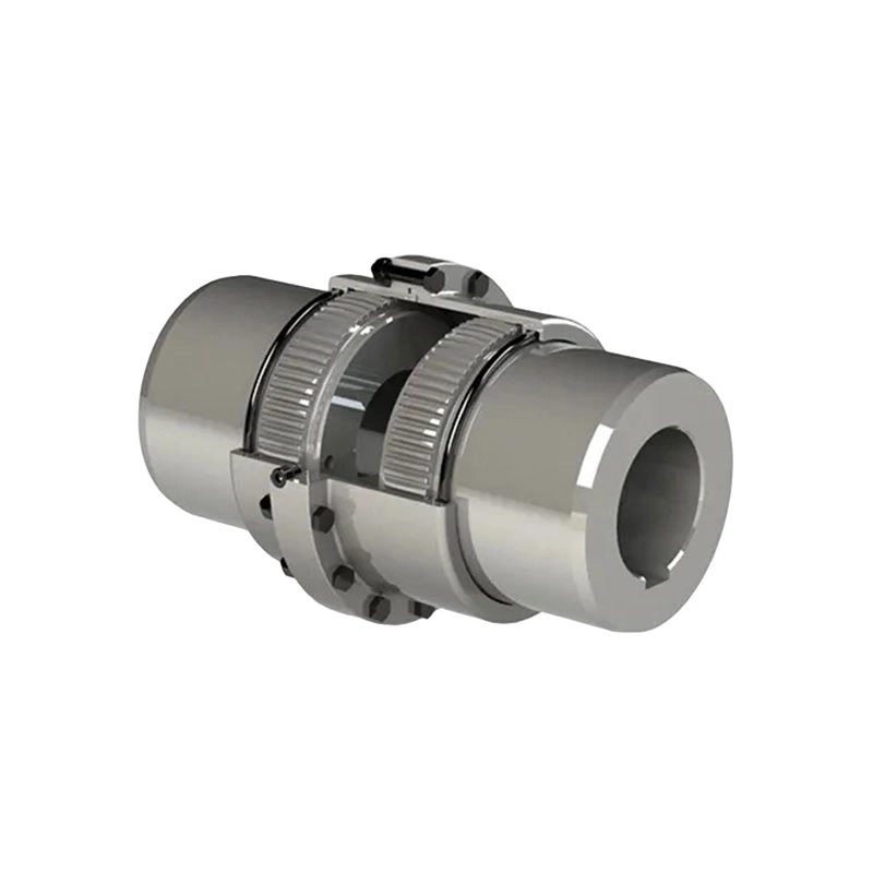
GBD Motor shaft extension drum gear coupling(Q/YG 11003X-2018)
4. Series Range and Technical Parameters
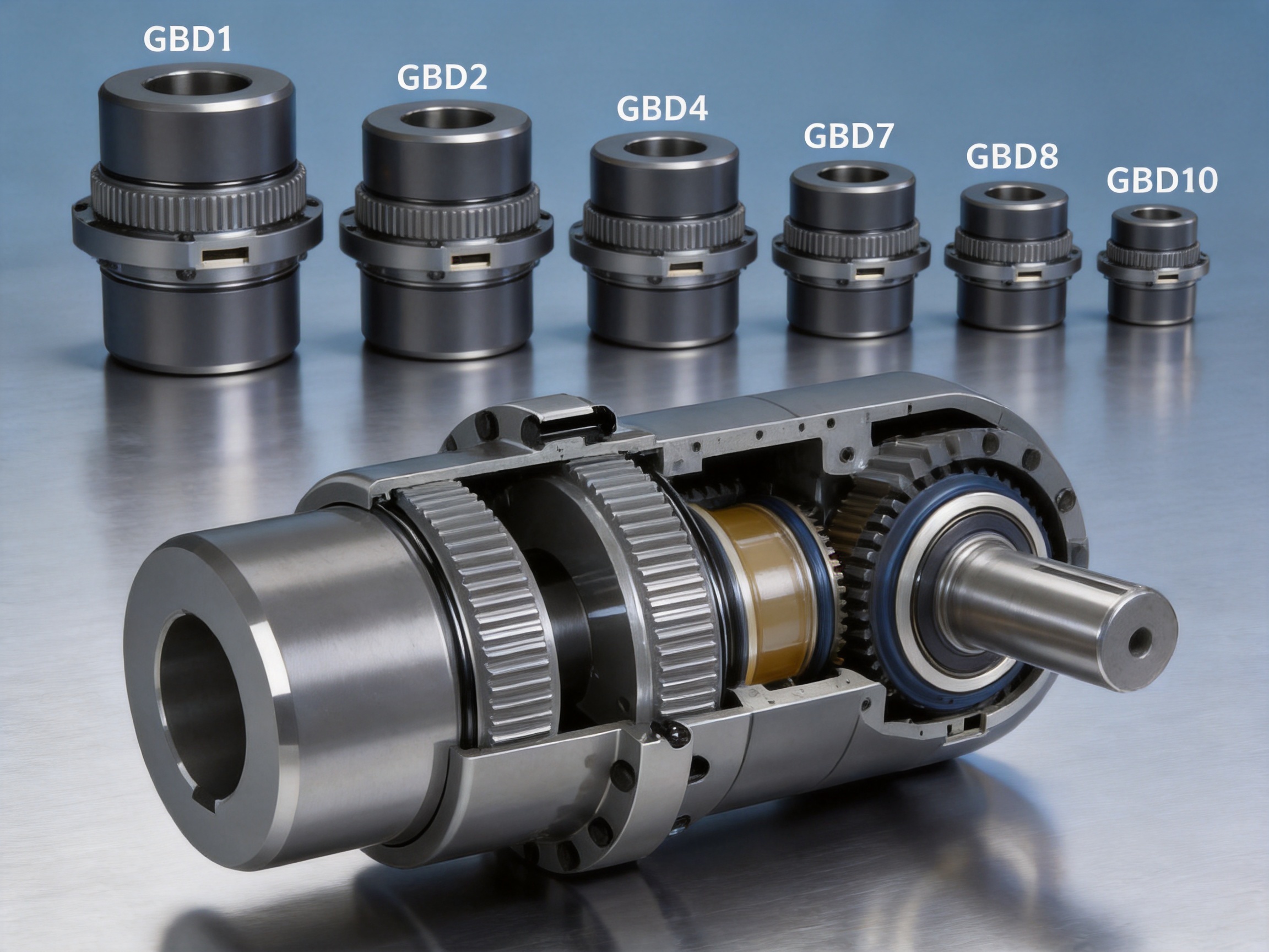
The GBD product family is organized into ten basic sizes. Each size covers a range of shaft bores and may be supplied with different bore configurations, including Type Y, Type J1, and Type Z1 arrangements. The available bore is selected according to the motor shaft, driven shaft, keyway requirements, and installation configuration.
| Model | Nominal Torque (kilonewton-metres) | Allowable Speed (revolutions per minute) | Representative Bore Range (millimetres) | Approximate Grease Quantity (millilitres) | Reference Mass Range (kilograms) |
| GBD1 | 1.6 | 5,600 | 22 to 56 | 107 | 6.2 to 9.6 |
| GBD2 | 2.8 | 5,100 | 38 to 65 | 137 | 11.2 to 16.4 |
| GBD3 | 4.5 | 4,600 | 40 to 75 | 201 | 17.2 to 22.4 |
| GBD4 | 6.3 | 4,300 | 45 to 90 | 238 | 25.2 to 35.6 |
| GBD5 | 8.0 | 4,000 | 50 to 105 | 298 | 31.6 to 53.9 |
| GBD6 | 11.2 | 3,700 | 55 to 115 | 465 | 40.5 to 67.5 |
| GBD7 | 18 | 3,350 | 60 to 135 | 561 | 63.9 to 106.7 |
| GBD8 | 25 | 3,000 | 65 to 150 | 734 | 81.7 to 123 |
| GBD9 | 36.1 | 2,700 | 70 to 175 | 956 | 112 to 212 |
| GBD10 | 56 | 2,450 | 75 to 200 | 1,320 | 161 to 319 |
The data in the table summarizes the principal size range. Detailed dimensions vary according to the selected bore. For example, the GBD1 series uses several bore groups, including 22 and 24 millimetres, 25 and 28 millimetres, 30 through 38 millimetres, and 40 through 56 millimetres. Each bore group has its own shaft-hole length, inertia, and mass.
As the coupling size increases, the allowable speed generally decreases. This relationship is typical for larger rotating components because greater diameter and mass increase centrifugal effects, balancing requirements, and dynamic loading. The selection of a large coupling for a high-speed application therefore requires careful review of the allowable speed and balancing condition.
The listed moments of inertia increase from approximately 0.00875 kilogram-metres squared for the smallest GBD1 configuration to more than 3.4 kilogram-metres squared for the largest GBD10 configuration. Moment of inertia is important when calculating acceleration time, motor starting performance, braking requirements, and dynamic response.
The shaft-hole length and outside dimensions also change with the bore group. Equipment designers should check the complete dimensional drawing rather than relying only on the model designation. Available installation space, shaft extension length, keyway position, guard clearance, and maintenance access should all be confirmed before ordering.
5. Manufacturing Process and Quality Control
5.1 Engineering Design and Application Review
Reliable coupling production begins with correct engineering input. Before manufacturing a GBD coupling, the application should be evaluated according to torque, rotational speed, shaft diameter, operating temperature, duty cycle, shock conditions, misalignment, installation position, environmental contamination, and lubrication requirements.
The company provides standard GBD models as well as customized coupling solutions. This capability is important because industrial drive systems frequently include unusual shaft dimensions, restricted installation spaces, special keyways, non-standard connection lengths, or unique environmental requirements.
Engineering review can determine whether a standard size is adequate or whether a modified design is needed. It can also identify potential problems such as excessive starting torque, insufficient shaft strength, inadequate bearing capacity, or a mismatch between the coupling’s allowable speed and the machine’s operating speed.
5.2 Material Preparation and Component Manufacturing
The primary components of a drum gear coupling must maintain strength, dimensional stability, and wear resistance. Production therefore requires suitable metal materials, controlled machining, and process discipline. Gear hubs, sleeves, flanges, covers, and related components must be manufactured according to approved drawings and tolerances.
Heavy-duty production equipment supports the manufacture of larger coupling components, while precision workshop capabilities are used for gear teeth, bores, keyways, sealing surfaces, and mating interfaces. Separating heavy fabrication from precision machining helps manufacturers manage different equipment requirements and maintain appropriate working conditions for each stage.
The gear teeth require particular attention. Tooth form, pitch, runout, flank finish, and concentricity directly affect load distribution and operating smoothness. If the tooth surfaces are not accurately produced, the coupling may experience localized contact, increased noise, heat generation, and accelerated wear.
5.3 Precision Machining
Precision machining controls the dimensions that determine how the coupling fits onto the shafts and how the gear elements engage. Bore accuracy is important because excessive clearance can cause impact and fretting, while insufficient clearance can make installation difficult or create assembly stress.
Concentricity is equally important. The bore, gear teeth, outside diameter, and flange surfaces must be correctly related to one another. Poor concentricity can create imbalance at high speed and increase radial forces during operation.
Keyways and other shaft connection features must be machined accurately so that torque is transferred securely. The design must also prevent stress concentration at sharp corners or transitions. Deburring, surface treatment, and inspection of all functional surfaces are part of the overall quality process.
5.4 Heat Treatment and Surface Performance
Where specified by the design, heat treatment can improve the hardness, strength, and wear resistance of gear teeth and other highly loaded components. The exact process depends on material grade, component size, tooth geometry, and required mechanical properties.
Heat treatment must be controlled carefully because excessive distortion can affect gear engagement and concentricity. Post-treatment inspection and finishing operations may be required to ensure that the components remain within dimensional tolerances.
The performance objective is not simply to make the teeth hard. The gear must achieve an appropriate balance between surface wear resistance and core toughness. A tough core helps resist shock and fatigue, while a durable tooth surface helps withstand repeated contact stress and sliding motion.
5.5 Assembly and Lubricant Retention
During assembly, the gear components, sleeve, seals, fasteners, and other parts must be installed according to the specified orientation and fit. Fasteners should be tightened using a controlled procedure, and sealing surfaces should be free from damage and contamination.
The internal reservoir must be capable of retaining the required quantity of grease around the gear teeth. Effective sealing helps prevent lubricant leakage and limits the entry of water, dust, scale, and other contaminants. In metallurgical, mining, and port environments, sealing performance is especially important because airborne particles and moisture can significantly accelerate gear wear.
5.6 Inspection and Testing
Quality control should cover raw materials, machining, heat treatment, assembly, dimensions, tooth geometry, sealing, balance, and final appearance. Depending on the order requirements, inspection may include dimensional measurement, hardness testing, non-destructive examination, rotational testing, and verification of the lubricant chamber.
Testing facilities and strict quality procedures allow the manufacturer to evaluate whether a finished coupling meets the technical requirements before shipment. This is particularly important for large couplings, customized products, and components intended for critical equipment where unplanned downtime can be expensive.
The company’s manufacturing strengths include research and development, production integration, technical support, standard product availability, customized engineering, testing capability, and after-sales service. These resources allow customers to work with one supplier from preliminary selection through production and installation support.
6. Advantages Compared with Alternative Coupling Types
6.1 Compared with Rigid Flange Couplings
Rigid flange couplings are structurally simple and can transmit torque efficiently when the shafts are accurately aligned. However, they do not compensate for operational misalignment. Any offset or angular error is transferred directly to the connected shafts, bearings, and machine housings.
The GBD coupling provides a more forgiving connection. Its gear structure allows controlled relative movement and can reduce the transmission of alignment-related forces. This makes it more suitable for large industrial equipment where shaft alignment may change during operation.
The trade-off is that a GBD coupling contains more components and requires lubrication. A rigid coupling may be appropriate for a short, accurately aligned drive, while the GBD is better suited to heavy-duty systems requiring flexibility and torque capacity.
6.2 Compared with Elastomeric Couplings
Elastomeric couplings use flexible materials to absorb vibration and accommodate misalignment. They can be easy to install and may operate without grease. However, the elastic element can be affected by temperature, chemical exposure, fatigue, aging, and repeated shock loading.
The GBD coupling replaces the elastomeric element with a metal gear mechanism. This gives it a strong advantage in applications involving high torque, high temperature, heavy loads, and severe mechanical duty. It can also provide more consistent dimensional behavior over long operating periods.
Elastomeric couplings may still be preferable where excellent vibration isolation, quiet operation, or simple maintenance is the primary requirement. The choice should be based on the full operating environment rather than on torque alone.
6.3 Compared with Metallic Elastic-Element Couplings
Diaphragm, disc, grid, and other metallic elastic-element couplings offer valuable flexibility and, in some cases, do not require grease. They can be highly effective in precision or high-speed applications. However, their allowable misalignment, shock capacity, axial movement, and installation requirements differ from those of a gear coupling.
The GBD series is particularly strong in high-torque and heavy-duty applications. Its distributed gear-tooth engagement is suitable for equipment with substantial load variation and demanding industrial service. It is often selected when the primary requirements are torque capacity, compactness, and robust misalignment accommodation.
6.4 Compared with Chain and Belt Connections
Chain and belt drives can provide useful speed reduction or separation between shafts, but they require additional space and may need tensioning, guarding, and periodic adjustment. They also introduce wear components such as chains, sprockets, belts, and pulleys.
A GBD coupling is a direct shaft-to-shaft connection. It does not provide speed reduction, but it transfers torque in a compact arrangement and can be integrated into a motor-driven machine without the footprint of a separate belt or chain system.
7. Applications in Heavy Industry
7.1 Metallurgical Equipment
Metallurgical machinery operates under high temperatures, heavy loads, vibration, scale contamination, and frequent acceleration or deceleration. Rolling mills, material handling equipment, furnace systems, and processing lines require couplings that can withstand demanding torque cycles.
The GBD coupling’s metal construction and gear-based flexibility make it suitable for these conditions. Its ability to accommodate shaft movement helps protect bearings and connected machinery when structures expand thermally or experience load-induced deflection.
7.2 Mining Machinery
Mining equipment is exposed to dust, impact, vibration, and irregular loads. Crushers, conveyors, hoists, feeders, and processing machinery often experience sudden changes in resistance when material enters the working zone.
A drum gear coupling can provide the torque capacity and shock resistance required in these drive systems. Proper sealing and lubrication are essential in dusty environments, and maintenance teams should inspect the coupling regularly for contamination, leakage, tooth wear, and abnormal noise.
7.3 Lifting and Conveying Machinery
Cranes, hoists, winches, conveyors, and port handling machines require dependable torque transmission during starting, stopping, lifting, lowering, and reversing. These operating cycles can create dynamic loads that are considerably higher than the steady running torque.
The GBD coupling can help manage the mechanical connection between motors, gearboxes, drums, and other drive components. Its flexibility can reduce the consequences of small alignment changes, while its metal gear construction supports repeated load cycles.
7.4 Hydraulic Engineering Equipment
Hydraulic gates, water-control machinery, pumping equipment, and other hydraulic engineering systems may operate outdoors and face moisture, temperature variation, and long periods between maintenance intervals.
When correctly sealed and lubricated, the GBD coupling offers a durable shaft connection for pumps, drives, and auxiliary machinery. Environmental protection should be considered during selection, especially where the coupling may be exposed to water spray or high humidity.
7.5 Papermaking Machinery
Paper production equipment requires stable and continuous operation. Roll drives, dryers, winding systems, and conveying equipment may run for long periods at consistent speeds while remaining sensitive to vibration and alignment changes.
The GBD coupling can support stable torque transmission in these systems. The correct size and speed rating should be selected carefully, and periodic lubrication checks should be incorporated into the plant’s preventive maintenance schedule.
7.6 General Industrial Drive Systems
The coupling is also suitable for fans, pumps, compressors, conveyors, mixers, crushers, processing lines, and other industrial machines where a motor must be connected to a driven shaft. Its broad size range allows it to serve both medium-duty and heavy-duty requirements.
For customized machinery, the manufacturer can evaluate non-standard shaft dimensions, special mounting requirements, modified lengths, alternative materials, and other design conditions. This is a significant advantage for original equipment manufacturers and engineering contractors working on specialized projects.
8. Installation Guidelines
Before installation, verify the coupling model, bore diameter, shaft-hole length, keyway arrangement, rotation direction, allowable speed, and torque rating. Confirm that the motor and driven machine shafts are clean, undamaged, and free from burrs.
Check the shaft alignment using suitable measuring equipment. The initial alignment should be as accurate as reasonably possible, even though the coupling can compensate for certain operational movement. Good alignment reduces tooth loading, lowers bearing forces, and extends service life.
Inspect all coupling components before assembly. Gear teeth should be free from dents, corrosion, machining debris, and excessive surface damage. Seals should be correctly positioned, and fasteners should match the specified grade and dimensions.
Install the hubs or gear components onto the shafts according to the selected bore and key arrangement. Avoid striking precision components directly with a hammer. If heating is used to assist installation, the method must not damage seals, lubricant, surface treatments, or nearby components.
After positioning the shafts, assemble the sleeve and related housing components. Tighten fasteners in a controlled sequence and to the recommended torque. Confirm that the coupling can rotate freely by hand before connecting the motor to the power supply.
Fill the coupling with the correct quantity and grade of grease. The lubricant must be compatible with the coupling materials, operating temperature, rotational speed, and load. Do not mix incompatible grease types unless the lubricant manufacturer confirms compatibility.
Install a suitable guard before commissioning. A rotating coupling can cause severe injury if exposed. The guard should provide adequate clearance, allow ventilation where required, and permit inspection and lubrication without creating unnecessary safety risks.
9. Maintenance and Service Practices
Routine maintenance should include visual inspection, leakage checks, temperature monitoring, noise observation, vibration monitoring, and confirmation that fasteners remain secure. Any sudden change in noise or temperature may indicate insufficient lubrication, tooth damage, excessive misalignment, seal failure, or an overloaded drive.
Lubricant should be inspected and replenished according to the operating environment and maintenance plan. Heavy dust, moisture, high temperature, frequent starts, and shock loading may require more frequent service than clean, steady-speed operation.
When adding grease, use the specified quantity and avoid overfilling. Excess grease can increase churning losses and temperature, while insufficient grease can cause rapid tooth wear. The coupling should be allowed to cool and isolated from its power source before maintenance begins.
During scheduled shutdowns, inspect the gear teeth for pitting, scoring, spalling, abnormal polishing, corrosion, or uneven contact. Check seals for hardening, cracking, or leakage. Inspect the shaft connection for fretting, looseness, key damage, or movement between the hub and shaft.
If tooth wear is concentrated on one edge, investigate alignment and shaft deflection before replacing the coupling. Replacing worn components without correcting the underlying cause may result in repeated failure.
Maintenance records should include the inspection date, operating hours, lubricant type and quantity, measured vibration, observed temperature, alignment results, and replaced components. This information helps identify trends and supports preventive maintenance decisions.
10. Product Selection Procedure
The first selection factor is the required torque. Determine the continuous operating torque, peak torque, starting torque, braking torque, and any cyclic or impact loads. Apply an appropriate service factor based on the machine type and duty cycle.
The second factor is speed. Compare the actual operating speed and maximum transient speed with the allowable speed of the selected GBD model. High-speed applications require particular attention to balance, installation accuracy, and guard clearance.
The third factor is shaft bore. Verify both shaft diameters, keyway dimensions, shaft extension lengths, and the required bore configuration. The selected coupling must fit without excessive clearance and must leave enough shaft engagement for reliable torque transmission.
The fourth factor is misalignment. Estimate the expected angular, radial, and axial movement during operation. The coupling should not be selected merely because it can tolerate a theoretical amount of misalignment; actual alignment should still be controlled during installation.
The fifth factor is the environment. Consider temperature, dust, water, corrosive substances, outdoor exposure, vibration, and accessibility. These conditions influence seal selection, lubricant choice, inspection frequency, and protective guarding.
The sixth factor is space and mass. Review the outside diameter, overall length, shaft-hole length, moment of inertia, mass, and maintenance clearance. Larger couplings may affect the inertia of the drive system and the size of the motor or braking equipment required.
When the application does not fit a standard model, provide the manufacturer with complete technical information. The company’s non-standard design capability can support special bore sizes, modified dimensions, customized connection arrangements, and application-specific engineering solutions.
11. Company Manufacturing and Service Strengths
Zhongye Heavy Industry Technology integrates research and development, manufacturing, sales, technical support, and after-sales service. Its product portfolio includes gear couplings, elastic sleeve pin couplings, elastic pin couplings, gear couplings with elastic pins, universal couplings, tire couplings, jaw couplings, star couplings, diaphragm couplings, drum couplings, grid couplings, Oldham couplings, flange couplings, clamp-shell couplings, roller chain couplings, safety couplings, and other specialized designs.
This broad product range provides an important engineering advantage. Customers can compare different coupling technologies through one technical organization instead of selecting a product without considering alternative transmission principles. The manufacturer can recommend a gear, elastic, diaphragm, grid, safety, or customized coupling according to the actual operating conditions.
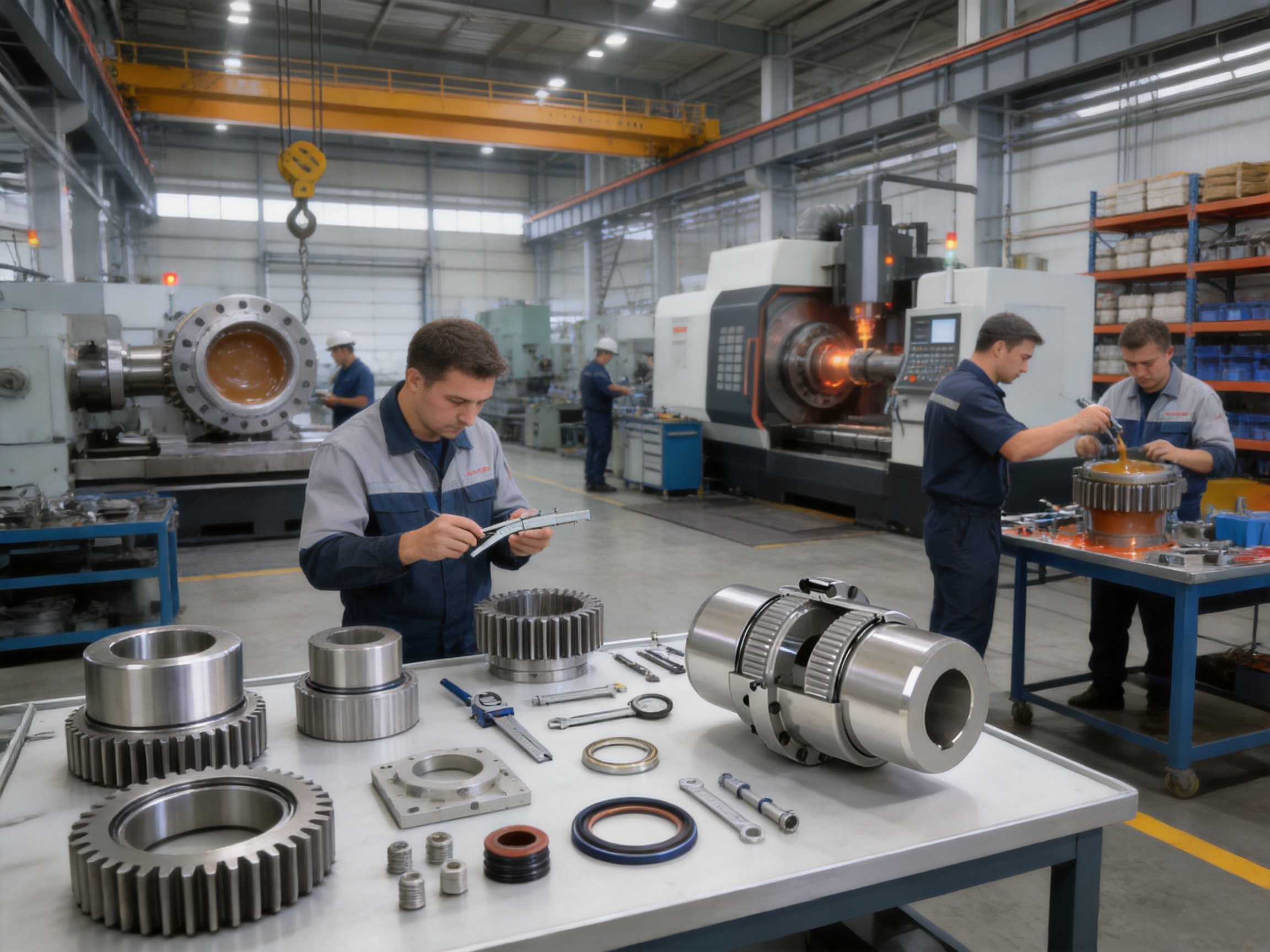
The company’s production site includes a heavy workshop, precision workshop, office and technical facilities, warehouse, dining facilities, roads, parking, and green areas. The approximately 16,463.52-square-metre new workshop area includes a 5,500-square-metre heavy workshop and a 4,600-square-metre precision workshop.
The heavy workshop supports the production and handling of large industrial components. The precision workshop provides an environment for controlled machining and assembly of gear couplings and other precision transmission products. This combination is suitable for manufacturing both standard series products and large custom components.
Advanced testing facilities and strict quality control support product verification. Testing may be applied to dimensions, materials, gear engagement, balance, mechanical condition, and final assembly. Quality procedures are intended to provide stable product performance and reduce the risk of field problems caused by manufacturing variation.
The company also emphasizes complete specifications, customization support, pre-sales technical assistance, non-standard design solutions, production guarantees, and after-sales service. These capabilities are valuable for customers who need more than a catalog product and require help with selection, interface dimensions, installation, maintenance, or replacement planning.
Its products are supplied for metallurgical equipment, mining equipment, water equipment, lifting equipment, papermaking equipment, port machinery, and other industrial fields. The company states that its products comply with relevant international standards and certifications, including ISO 9001 quality management requirements.
12. Reliability, Cost Efficiency, and Lifecycle Value
The purchase price of a coupling is only one part of its total cost. A coupling that is inexpensive but frequently fails can create substantial costs through production stoppage, emergency repair, bearing damage, shaft damage, labor, and safety risks.
The GBD coupling is designed to deliver lifecycle value through high torque capacity, long service potential, misalignment compensation, durable metal components, and compatibility with demanding industrial environments. By reducing the effects of shaft movement and load variation, it can help protect other drive components.
Its maintenance requirements should be considered realistically. Gear couplings require suitable grease, periodic inspection, and attention to seals. However, these activities can be integrated into planned maintenance programs. For many heavy-duty systems, the cost of regular lubrication is lower than the cost of replacing a failed elastic element or repairing damage caused by a rigid connection.
Standardized model sizes also simplify spare-parts planning. Industrial users can establish recommended stock levels for frequently used coupling sizes, seals, fasteners, and lubricant. The availability of customized designs further allows replacement units to match existing equipment when a standard coupling is not sufficient.
Correct selection remains essential to lifecycle performance. Even the strongest coupling can fail if it is overloaded, operated above its allowable speed, installed with excessive misalignment, filled with unsuitable grease, or exposed to conditions beyond its design assumptions.
13. Frequently Asked Questions
What type of coupling is the GBD series?
The GBD series is a flexible coupling with non-elastic metal elements. It uses a drum-gear transmission structure rather than a rubber, polymer, diaphragm, or spring element to provide flexibility and torque transmission.
What is the main purpose of the coupling?
Its main purpose is to connect a motor shaft with driven machinery while transmitting torque and accommodating operational axial, radial, and angular misalignment within the permitted range.
What torque range does the GBD series cover?
The listed models cover nominal torque ratings from 1.6 kilonewton-metres for GBD1 to 56 kilonewton-metres for GBD10.
What is the maximum allowable speed?
The highest listed allowable speed is 5,600 revolutions per minute for GBD1. Allowable speed decreases as coupling size increases, with GBD10 listed at 2,450 revolutions per minute.
What shaft diameters are available?
The series supports bore sizes from approximately 22 millimetres to 200 millimetres, depending on the model and bore configuration. Exact dimensions should be confirmed from the selected model drawing.
Does the coupling require lubrication?
Yes. The gear teeth require suitable grease for lubrication, cooling, and wear protection. The required grease quantity depends on the coupling size and selected configuration.
Can the coupling compensate for serious shaft misalignment?
The coupling compensates for normal operational misalignment, but it should not be used to correct poor installation or major shaft offset. Initial alignment must be performed carefully to protect the gear teeth, bearings, seals, and shafts.
Is the GBD coupling suitable for high-temperature applications?
Its metal transmission structure can be advantageous in high-temperature environments compared with some polymeric elastic elements. However, the allowable temperature of the grease, seals, and surrounding equipment must also be checked.
Where is the coupling commonly used?
Common applications include metallurgical equipment, mining machinery, cranes, hoists, conveyors, port equipment, hydraulic engineering machinery, papermaking equipment, pumps, and other heavy industrial drives.
Can customized couplings be manufactured?
Yes. The manufacturer undertakes non-standard coupling design and production. Customers should provide shaft sizes, torque, speed, dimensions, operating conditions, misalignment requirements, and installation limitations for engineering review.
What should be checked before ordering?
Check nominal and peak torque, speed, shaft diameters, keyways, shaft-hole lengths, allowable misalignment, outside dimensions, moment of inertia, environment, lubrication, guard space, and maintenance access.
How can abnormal coupling noise be investigated?
Abnormal noise may result from insufficient grease, seal damage, excessive misalignment, tooth wear, loose fasteners, shaft movement, or overloading. Stop the equipment safely, isolate the power source, inspect the coupling, and correct the underlying cause before restarting.
14. Conclusion
The GBD motor shaft extension drum gear coupling is a robust solution for industrial drive systems that require high torque transmission, compact construction, and compensation for shaft movement. Its metal gear structure provides an effective alternative to rigid couplings and to flexible couplings that rely on polymeric elastic elements.
The series covers a broad technical range, with models from GBD1 to GBD10, nominal torque from 1.6 to 56 kilonewton-metres, allowable speed up to 5,600 revolutions per minute, and bore sizes extending to approximately 200 millimetres. The internal grease reservoir, drum-shaped gear profile, durable construction, and multiple bore configurations support use across many heavy industrial applications.
Its strongest advantages are high torque density, resistance to shock loading, compensation for axial, radial, and angular misalignment, suitability for demanding environments, and the absence of a vulnerable polymeric insert. The coupling does require accurate installation, correct lubrication, suitable guarding, and scheduled inspection, but these requirements are manageable within a professional maintenance program.
The manufacturer strengthens the product offering through integrated research and development, heavy and precision manufacturing facilities, testing capabilities, a broad coupling portfolio, customized engineering, quality management, technical support, and after-sales service. This combination allows the GBD coupling to serve both standard equipment and specialized drive systems.
For metallurgical, mining, lifting, conveying, hydraulic, papermaking, port, and general industrial machinery, the GBD drum gear coupling provides a dependable connection between motor shafts and driven equipment. Correct model selection and disciplined maintenance are the keys to obtaining its full performance and service-life potential.
References
1. Q/YG 11003X-2018, Enterprise Standard for GBD Motor Shaft Extension Drum Gear Couplings.
2. Manufacturer-provided technical data for GBD1 through GBD10 coupling models.
3. Manufacturer-provided dimensional and application information for motor shaft extension drum gear couplings.
4. General engineering principles for industrial gear couplings, shaft alignment, lubrication, and power transmission.
5. ISO 9001 quality management system principles for manufacturing organizations.
Product: GBD Motor shaft extension drum gear coupling(Q/YG 11003X-2018)

- Quick Links
- About
- Products
- Our Service
- News & Events
- Contact
- Products Series
- Flexible Couplings with Non-Elastic Elements
- Flexible Couplings with Metal Elastic Elements
- Flexible Couplings with Non-Metallic Elastic Elements
- Safety Coupling
- Rigid Coupling
- Contact Us
- Tel : +86 511 8572 3800 +86 511 8572 3900
- Mobile : +86 15106109009
- Email : sales@couplingzy.com
- Add:No.1 Zhongye Yingbin Avenue, Gaozi Street, Dantu Economic Development Zone, Zhenjiang City, Jiangsu Province, China.


