:+86 15106109009
:sales@couplingzy.com


 English
 русский
 Español
 عربى
 Português
 Deutsch
 Türk
 Indonesia


SWC-WF Flange Universal Coupling for High-Torque Industrial Drive Systems
Content
- 1 Introduction
- 2 Product Definition and Operating Purpose
- 3 Principal Performance Characteristics
- 4 Technical Range and Model Selection
- 5 Advantages Compared with Other Coupling Types
- 6 Application Fields
- 7 Manufacturing Capability and Quality Advantages
- 8 Customization and Engineering Support
- 9 Installation Recommendations
- 10 Maintenance and Service Life
- 11 Selection Checklist
- 12 Q&A
- 12.1 What is the SWC-WF type coupling used for?
- 12.2 What does “without expansion welding” mean?
- 12.3 What is the maximum shaft angle?
- 12.4 What is the highest nominal torque in the range?
- 12.5 How does this coupling differ from a nylon gear coupling?
- 12.6 Can the coupling be customized?
- 12.7 Is the SWC-WF suitable for frequent axial movement?
- 12.8 What information is needed for a quotation?
- 12.9 What maintenance does the coupling require?
- 12.10 Where is the manufacturer located?
- 13 Conclusion
- 14 References
- 15 Product: SWC-WF type flange universal coupling without expansion welding
Introduction
Reliable torque transmission is essential in industrial equipment where large loads, long operating cycles, angular misalignment, and demanding environmental conditions are present at the same time. In applications such as paper production, metallurgy, chemical processing, mining, lifting machinery, port equipment, and general manufacturing, a coupling is not merely a connector between two shafts. It is a critical mechanical component that influences machine availability, vibration behavior, maintenance frequency, energy efficiency, and the service life of connected equipment.
The SWC-WF type flange universal coupling without expansion welding is designed for heavy-duty power transmission systems that require substantial angular compensation but do not normally require frequent axial compensation. Its non-expansion welded flange configuration combines a robust metal construction with a streamlined connection structure. The result is a coupling intended to deliver high torque capacity, dependable angular flexibility, convenient installation, and stable operation in demanding industrial environments.
With nominal torque ratings ranging from 22.4 kN·m to 1,000 kN·m, the series covers a broad range of drive requirements. The maximum permitted shaft angle is up to 15 degrees, giving designers greater flexibility when shafts cannot be arranged on a perfectly straight centerline. The product range includes models from SWC180WF through SWC550WF, allowing equipment builders to select a size based on torque, speed, shaft geometry, installation space, and service conditions.
Compared with lightweight nylon gear couplings, nylon sleeve gear couplings, and other compact flexible couplings, the SWC-WF series emphasizes structural rigidity, metal strength, high load capacity, and suitability for large industrial machinery. It can also be incorporated into more complex transmission systems alongside other coupling types when a production line requires different combinations of flexibility, alignment compensation, and installation convenience.
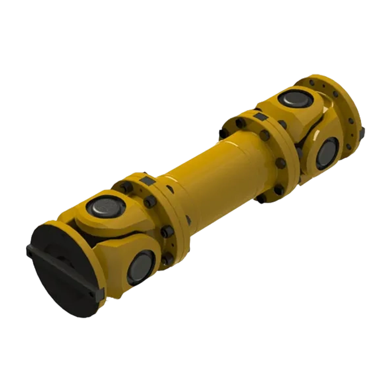
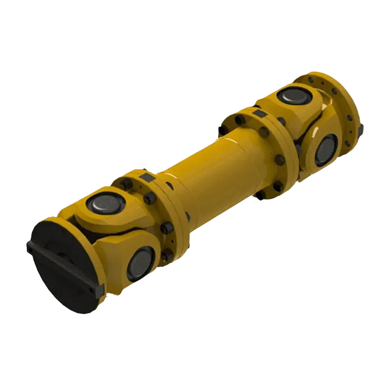
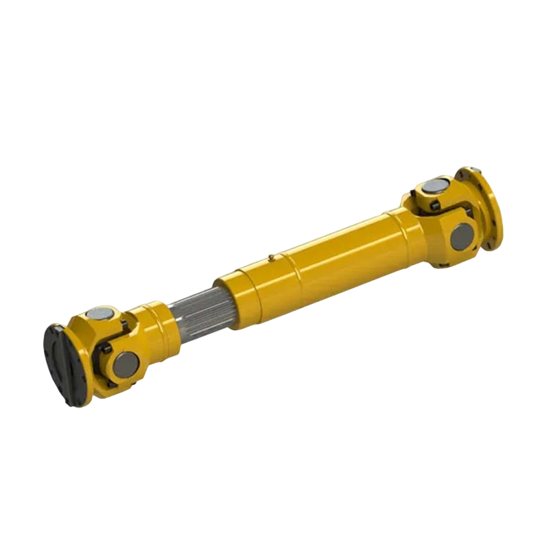
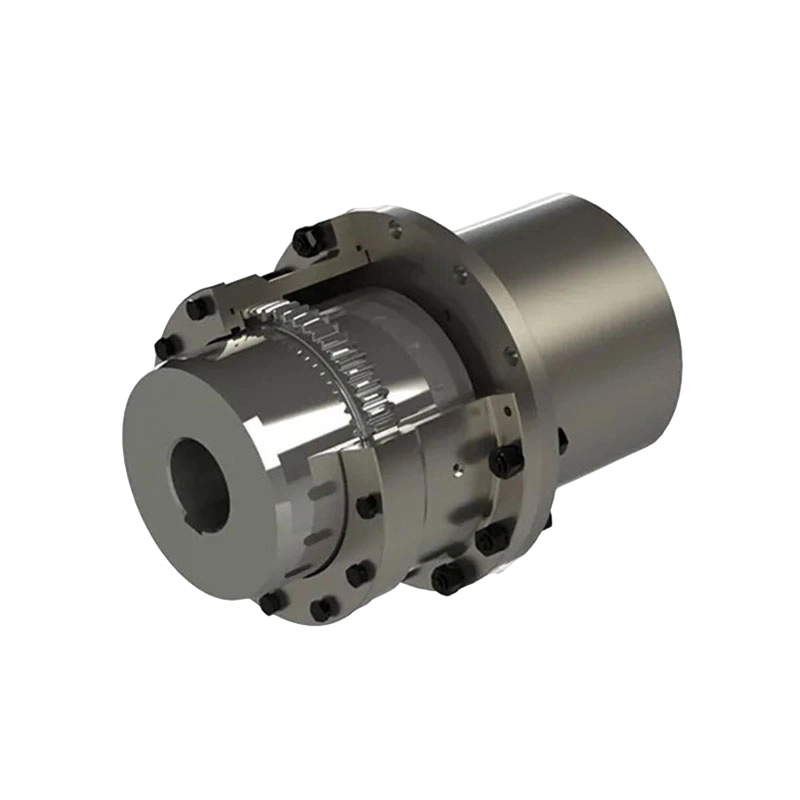
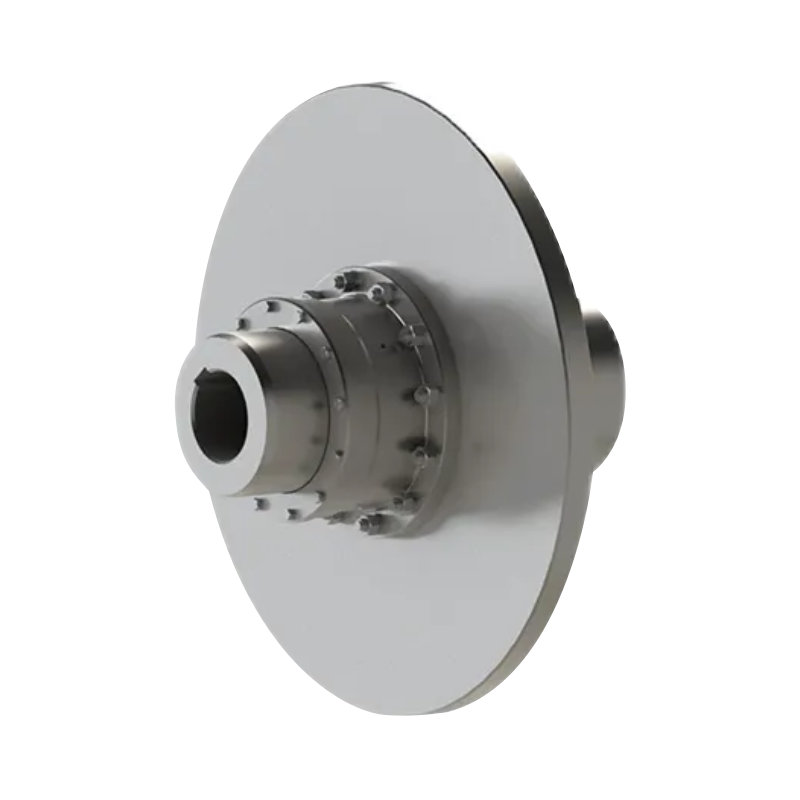
SWC-WF type flange universal coupling without expansion welding
Product Definition and Operating Purpose
A universal coupling is used to transmit rotational power between shafts whose centerlines are not perfectly aligned. Unlike a rigid flange coupling, a universal coupling can accommodate an angular relationship between connected shafts. This capability is particularly useful in heavy machinery where the driving and driven units are separated by a distance, mounted on different foundations, or subject to installation and operating deflections.
The SWC-WF design uses a metal non-elastic transmission element. In this context, “non-elastic” refers to the absence of a flexible rubber, polyurethane, or polymer element used as the primary torque-transmitting medium. The coupling obtains its flexibility from its universal-joint structure rather than from elastic deformation of a soft insert. This construction gives the product a firm torsional response and makes it suitable for systems where high torque, durability, and predictable mechanical behavior are more important than vibration isolation through a polymer element.
The flange configuration is designed to connect the coupling to adjacent shafts or equipment through bolted flange interfaces. The non-expansion welded arrangement provides a compact and mechanically strong structure without relying on a telescoping expansion section for routine axial movement. It is therefore particularly appropriate for systems in which the shaft distance is established during installation and remains generally stable during operation.
In practical terms, the SWC-WF series is suitable for transmitting power between motors, gearboxes, rolls, pumps, fans, conveyors, crushers, lifting mechanisms, and other heavy industrial machines. The actual selection must consider torque, speed, duty cycle, starting conditions, shaft angle, bore design, bearing life, environmental conditions, and applicable safety factors.
Principal Performance Characteristics
High Nominal Torque Capacity
The most prominent feature of the SWC-WF series is its high torque capability. The smallest listed model, SWC180WF, has a nominal torque of 22.4 kN·m. The largest listed model, SWC550WF, reaches 1,000 kN·m. This range allows the same general product family to serve both medium-sized heavy machinery and very large drive systems.
High torque capacity is valuable because it allows equipment designers to transmit substantial power without using several smaller couplings in parallel. A larger single coupling can simplify the shaft arrangement, reduce the number of connection points, and make alignment and maintenance planning more straightforward. It can also provide a greater mechanical reserve when the application experiences starting peaks, intermittent overloads, or load fluctuations.
The nominal torque rating should not be treated as the only selection criterion. A complete engineering review should also evaluate fatigue torque, operating speed, acceleration, braking, torsional oscillation, shock loading, and the number of starts per hour. Nevertheless, the high rated torque of the SWC-WF range provides a strong foundation for heavy-duty applications.
Angular Compensation up to 15 Degrees
The series permits a shaft angle of up to 15 degrees according to the supplied technical information. This is a significant angular compensation capability for a large metal coupling. It can help accommodate equipment layouts in which two shaft centerlines are intentionally arranged at an angle or where mechanical geometry makes a straight-line connection impractical.
Angular compensation can also help reduce the effects of minor installation deviations and operating deflection. For example, foundations may settle differently, frames may deform under load, or connected machinery may experience thermal movement. A universal coupling can accommodate these conditions more effectively than a rigid coupling, provided the actual angle remains within the permitted range and the installation is correctly completed.
The maximum angle should always be understood as a design limit, not as a target operating condition for every machine. Continuous operation at a large angle may influence bearing loads, rotational behavior, service life, and allowable speed. Proper application engineering should determine the permissible angle for the actual speed, load, lubrication arrangement, and duty cycle.
Metal Construction for Heavy Industrial Service
The metal construction of the SWC-WF series gives it a distinct position among flexible coupling products. Many compact couplings use nylon or other polymer components to reduce weight and simplify assembly. Those products can be advantageous in light and medium-duty applications, but they may not provide the same structural reserve, heat tolerance, or load capacity required by very large machinery.
The SWC-WF series is intended for applications in which the coupling must withstand high transmitted torque and continuous mechanical stress. Its metal transmission structure supports a firm connection between the driving and driven shafts. This is especially useful where torsional stiffness, dimensional stability, and resistance to mechanical wear are important design considerations.
Metal components also provide a useful solution for industrial environments where elevated temperature, oil exposure, dust, process contamination, or heavy impact may limit the use of polymer elements. The exact material, heat treatment, surface protection, and lubrication requirements should be confirmed according to the selected specification and operating environment.
Non-Expansion Configuration
The non-expansion welded flange design is intended for systems that do not require frequent axial compensation. By avoiding a telescoping expansion structure, the coupling can maintain a relatively direct and rigid mechanical arrangement. This can be beneficial when axial movement is limited and the primary requirement is torque transmission combined with angular compensation.
A non-expansion configuration may also support more predictable installation dimensions. The equipment designer can work with defined minimum lengths and flange dimensions when laying out the drive system. This is useful for large machines where available space is limited and the coupling must fit within a carefully controlled envelope.
However, the absence of an expansion section means that shaft positioning must be planned accurately. If the equipment experiences substantial thermal growth or regular axial movement, a different coupling configuration may be more appropriate. The SWC-WF should be selected when the application conditions correspond to the product’s intended operating principle.
Technical Range and Model Selection
The following table summarizes the principal data supplied for the SWC-WF series. Dimensions and ratings should be verified against the final technical drawing and application conditions before manufacturing or installation.
| Model | Rotation Diameter D (mm) | Nominal Torque Tn (kN·m) | Fatigue Torque Tf (kN·m) | Bearing Life Factor L | Maximum Shaft Angle (degrees) | Minimum Length Lmin (mm) | D1 (mm) | D2 (mm) | D3 (mm) | Lm (mm) | Bolt Arrangement | Mass at Lmin (kg) | Mass Increase per 100 mm (kg) |
|---|---|---|---|---|---|---|---|---|---|---|---|---|---|
| SWC180WF | 180 | 22.4 | 11.2 | 0.245 | 15 | 560 | 155 | 105 | 114 | 110 | 8 x diameter 17 | 58 | 2.8 |
| SWC200WF | 200 | 36 | 18 | 1.115 | 15 | 585 | 170 | 120 | 133 | 115 | 8 x diameter 17 | 82 | 3.7 |
| SWC225WF | 225 | 56 | 28 | 7.812 | 15 | 610 | 196 | 135 | 152 | 120 | 8 x diameter 17 | 93 | 4.9 |
| SWC250WF | 250 | 80 | 40 | 28.2 | 15 | 715 | 218 | 150 | 168 | 140 | 8 x diameter 19 | 143 | 5.3 |
| SWC285WF | 285 | 120 | 58 | 82.8 | 15 | 810 | 245 | 170 | 194 | 160 | 8 x diameter 21 | 220 | 6.3 |
| SWC315WF | 315 | 160 | 80 | 279 | 15 | 915 | 280 | 185 | 219 | 180 | 10 x diameter 23 | 300 | 8.0 |
| SWC350WF | 350 | 225 | 110 | 744 | 15 | 980 | 310 | 210 | 245 | 194 | 10 x diameter 23 | 387 | 11.5 |
| SWC390WF | 390 | 320 | 160 | 1,860 | 15 | 1,100 | 345 | 235 | 267 | 215 | 10 x diameter 25 | 588 | 15.0 |
| SWC440WF | 440 | 500 | 250 | 8,250 | 15 | 1,290 | 390 | 255 | 325 | 260 | 16 x diameter 28 | 880 | 21.7 |
| SWC490WF | 490 | 700 | 350 | 21,540 | 15 | 1,360 | 435 | 275 | 351 | 270 | 16 x diameter 31 | 1,263 | 27.3 |
| SWC550WF | 550 | 1,000 | 500 | 63,350 | 15 | 1,510 | 492 | 320 | 426 | 305 | 16 x diameter 31 | 1,663 | 34.0 |
Understanding the Size Designation
The numerical portion of each model designation corresponds to the nominal rotation diameter. As the model number increases, the rotation diameter, torque rating, minimum length, mass, and other principal dimensions generally increase. This progression provides a logical selection path for engineers who begin with the required torque and then verify the available installation envelope.
For example, a system requiring a nominal torque near 80 kN·m may begin its evaluation with the SWC250WF model. A drive requiring approximately 320 kN·m may be evaluated with the SWC390WF model, while a system approaching 1,000 kN·m may require the SWC550WF model. These examples are only preliminary references. Service factors, fatigue requirements, speed, shaft dimensions, and dynamic loads must be reviewed before final selection.
Torque and Fatigue Considerations
The table lists both nominal torque and fatigue torque. Nominal torque is commonly used as a primary rating for continuous or representative operation, while fatigue torque provides an important indication for repeated or fluctuating loads. Applications with frequent starts, stops, reversals, impact loading, or cyclic torque should not be selected solely on the basis of nominal torque.
Engineers should identify the normal operating torque, peak torque, starting torque, braking torque, and any torsional oscillation generated by the drive. A suitable service factor should then be applied based on the machine type and duty cycle. If the coupling is used in a paper machine, rolling line, crusher, crane, or conveyor with severe starting conditions, the dynamic analysis may be as important as the steady-state calculation.
Where the operating torque varies significantly, a larger model may be preferable even if the average torque appears acceptable. This additional capacity can reduce mechanical stress and improve resistance to fatigue. The final design should also examine the compatibility of the coupling with the shaft, key, flange bolts, bearings, and connected equipment.
Advantages Compared with Other Coupling Types
Compared with Rigid Flange Couplings
Rigid couplings can provide excellent torsional stiffness and a simple connection when two shafts are accurately aligned and remain aligned under all operating conditions. Their limitation is that they offer little or no compensation for angular misalignment. Even a small alignment error can generate additional bearing loads, shaft bending, vibration, and premature wear.
The SWC-WF series offers a more adaptable solution because its universal-joint construction permits angular compensation up to 15 degrees. This makes it better suited to shaft systems in which alignment cannot remain perfectly collinear. At the same time, its metal structure maintains a firm torque path rather than relying on a soft elastic insert.
Rigid couplings may still be preferable where alignment is precise, movement is negligible, and maximum torsional rigidity is the only consideration. The SWC-WF becomes more attractive when high torque must be transmitted across an angular shaft arrangement.
Compared with Nylon Gear Couplings
Nylon gear couplings are valued for their low weight, relatively simple structure, and convenient installation. They can be an efficient choice for moderate torque applications and environments where compactness is important. Their polymer components, however, may impose limitations related to temperature, chemical exposure, long-term wear, or very high torque.
The SWC-WF series is designed for a different performance range. Its metal construction and large structural dimensions make it more suitable for heavy machinery and high torque transmission. It can provide a stronger mechanical reserve in applications where a lightweight nylon coupling would be undersized or where the operating environment is too severe for polymer elements.
The trade-off is that the SWC-WF is heavier and requires more substantial supporting equipment, lifting arrangements, and installation planning. A nylon coupling may be more economical for a small motor or lightly loaded machine, while the SWC-WF is designed for industrial systems in which capacity and durability have priority.
Compared with Nylon Sleeve Gear Couplings
Nylon sleeve gear couplings use a flexible sleeve to connect toothed hubs. They are often selected for compact drives, moderate misalignment, and simplified maintenance. Their relatively low mass can be useful in high-speed applications where rotating inertia must be minimized.
By contrast, the SWC-WF series is intended for large-scale torque transmission and high angular compensation. It is particularly advantageous when the coupling must bridge a longer distance or connect shafts with a substantial angular relationship. Its flange-based structure can also be integrated into large mechanical assemblies where a sleeve coupling would not provide adequate torque capacity or mechanical reserve.
Selection should be based on the complete operating profile rather than on product category alone. A nylon sleeve coupling may offer a practical solution for a smaller and cleaner drive, whereas the SWC-WF is more appropriate for large industrial machinery exposed to high loads and demanding working conditions.
Compared with Elastic Element Couplings
Elastic couplings use rubber, polyurethane, or another resilient component to compensate for misalignment and reduce vibration. They can be useful when shock absorption, noise reduction, and torsional damping are important. Their limitations may include temperature sensitivity, aging, chemical compatibility, and finite elastic element life.
The SWC-WF series uses a non-elastic metal transmission principle. It is therefore more focused on high torque, structural stability, and predictable angular compensation than on damping torsional vibration through a soft element. For machinery with severe torque and a need for a rigid, durable connection, this can be a major advantage.
Where the connected machinery is sensitive to torsional resonance or impact, the engineering team should evaluate whether a damping coupling or an additional torsional control measure is needed. The SWC-WF can be combined with other transmission components in a larger system, but the entire drive must be assessed as a dynamic assembly.
Application Fields
Paper and Pulp Equipment
Paper production lines contain long drive trains, rolls, drying equipment, conveyors, and process machinery that may operate continuously for long periods. Alignment can be affected by thermal changes, foundation movement, and the arrangement of multiple machine sections. A high-capacity universal coupling can help connect drive components while accommodating the required angular relationship.
The SWC-WF series is suitable for heavy paper equipment where reliability and operating continuity are important. Its metal structure is appropriate for industrial environments in which the coupling may be exposed to moisture, process residue, lubricants, and continuous mechanical loading. The selected model should be checked against roll speed, torque fluctuation, balance requirements, and maintenance access.
Chemical Processing Equipment
Chemical plants use mixers, pumps, agitators, compressors, conveyors, and other rotating machines. The correct coupling must be compatible with the surrounding temperature, chemicals, safety requirements, and operating duty. A metal universal coupling can provide a robust connection where polymer elements may require additional chemical compatibility verification.
In chemical service, material selection and surface protection remain essential. The coupling should be protected from corrosive media, and any lubrication system should be selected for the actual temperature and chemical conditions. Where hazardous-area rules apply, the complete rotating assembly must be evaluated according to the relevant plant standards.
Metallurgical and Rolling Equipment
Metallurgical machinery frequently produces high torque, impact loads, vibration, and rapid load changes. Rolling mills, processing lines, conveyors, and auxiliary equipment require components that can withstand repeated mechanical stress. The high torque range and metal construction of the SWC-WF series make it suitable for preliminary evaluation in these demanding systems.
Rolling equipment may also require careful consideration of shaft angle, bearing life, rotational speed, and torsional resonance. The coupling should be selected with an appropriate fatigue margin, and all flange bolts and shaft connections should be designed to withstand the actual load spectrum.
Mining and Bulk Material Handling
Mining machinery and bulk handling systems often operate in dusty environments and experience heavy starts, variable loads, and occasional impact. Conveyors, crushers, feeders, winches, and hoisting equipment can benefit from a coupling with high torque capacity and robust metal components.
The coupling enclosure, lubrication, sealing, and inspection plan should be adapted to the site conditions. Dust ingress, water exposure, low temperature, and limited access can all influence service life. Correct installation and regular inspection are particularly important when the coupling is used in remote or difficult-to-reach equipment.
Lifting and Port Equipment
Cranes, hoists, ship loaders, and port machinery require reliable transmission under acceleration, deceleration, braking, and reversing conditions. These machines may also experience structural deflection as the load changes. A universal coupling can provide angular flexibility between drive components while maintaining high torque transmission capability.
For lifting equipment, safety factors and braking loads must be evaluated carefully. The coupling is one part of a complete load path that may include motors, gearboxes, brakes, drums, drums shafts, bearings, and structural supports. The final design should comply with the applicable lifting equipment standards and inspection procedures.
Manufacturing Capability and Quality Advantages
The product is manufactured by Zhongye Heavy Industry Technology (Zhenjiang) Co., Ltd., a company that integrates research and development, manufacturing, and sales. Its product portfolio includes toothed couplings, elastic sleeve column pin couplings, universal couplings, tire couplings, jaw couplings, diaphragm couplings, drum couplings, grid couplings, Oldham couplings, flange couplings, roller chain couplings, safety couplings, and custom non-standard coupling assemblies.
This broad product range is valuable because it gives the manufacturer experience across multiple coupling principles. Engineers can compare elastic, non-elastic, rigid, gear, diaphragm, drum, and universal coupling structures when developing a solution. This wider technical perspective is useful for applications where a standard catalog coupling does not fully satisfy the load, space, or alignment requirements.
Integrated Research and Development
Research and development is important for large couplings because the product must be designed as a complete mechanical system rather than as an isolated component. Load transmission, bearing arrangement, shaft angle, flange strength, balance, lubrication, sealing, and maintenance access all interact with one another.
An integrated development process allows the manufacturer to adapt dimensions, connection details, materials, and performance requirements to the customer’s equipment. This is especially helpful for replacement projects, modernization work, and machinery with restricted installation space. Non-standard design support can also reduce the need for extensive modifications to existing equipment.
Heavy and Precision Workshop Resources
The company’s new workshop covers approximately 16,463.52 square meters. It includes a heavy workshop of about 5,500 square meters, a precision workshop of about 4,600 square meters, an office building and gymnasium, a dining hall, a warehouse, and supporting roads and green areas.
The combination of heavy and precision workshop capacity is particularly relevant to universal couplings. Large coupling bodies and flange components require sufficient space and handling capability, while bearing seats, bores, keyways, bolt patterns, and mating surfaces require accurate machining. Separating heavy fabrication and precision processing functions can support a more organized production flow.
Heavy workshop resources support the manufacture and handling of large components, including high-torque coupling assemblies with substantial mass. Precision workshop resources support the dimensional control required for shaft connections, rotating components, bearing locations, and flange interfaces. Together, these capabilities contribute to a more reliable finished product.
Machining and Dimensional Control
Dimensional accuracy is essential for coupling performance. Incorrect bore dimensions, flange runout, bolt-circle errors, or bearing-seat tolerances can make installation difficult and may create vibration during operation. Precision machining and inspection therefore form an important part of the production process.
Manufacturing control should include verification of critical dimensions, concentricity, surface finish, keyway geometry, bolt-hole location, and assembly fit. For rotating parts, balance and runout should also be evaluated according to the operating speed and customer requirements. These controls help ensure that the coupling performs consistently after installation.
Material and Heat Treatment Management
High-torque coupling components must be manufactured from materials appropriate to their stress and operating conditions. Depending on the component, material selection may influence tensile strength, toughness, wear resistance, fatigue performance, machinability, and response to heat treatment.
A controlled manufacturing process should include material identification, supplier verification, heat treatment records where applicable, and inspection of finished components. Proper heat treatment can improve the strength and durability of highly loaded parts, while suitable surface protection can help defend against corrosion and industrial contamination.
Assembly and Inspection
Assembly quality affects the actual performance of a coupling as much as component design. Bearings, shafts, flanges, fasteners, seals, and lubricated interfaces must be assembled in the correct sequence and adjusted according to the technical requirements. Improper assembly can produce excessive friction, uneven loading, vibration, or premature wear even when all individual components meet their dimensional specifications.
Final inspection should confirm the model, dimensions, rotation direction where relevant, bolt arrangement, lubrication provisions, and overall assembly condition. Inspection records provide traceability and help customers maintain consistent maintenance documentation throughout the service life of the equipment.
Quality Management and Certification
The company states that its products comply with international standards and certifications such as ISO 9001. A quality management system provides a framework for process control, documentation, corrective action, supplier management, and continual improvement.
For customers purchasing large industrial couplings, quality documentation can be an important part of project approval. Depending on the application, documentation may include material certificates, dimensional inspection reports, test records, assembly instructions, lubrication recommendations, and installation drawings. The exact documentation package should be agreed before order confirmation.
Customization and Engineering Support
Standard models provide an efficient starting point, but many heavy industrial applications require customization. Shaft diameters, flange dimensions, keyways, installation lengths, bolt patterns, protective covers, lubrication arrangements, and operating angles may differ from the standard catalog configuration.
The manufacturer undertakes the design and manufacture of non-standard couplings. This capability can be useful when replacing an obsolete coupling, matching an existing shaft arrangement, adapting to restricted space, or integrating the coupling into a newly designed production line.
To develop a suitable customized solution, customers should provide as much application information as possible. Important data includes motor power, speed, nominal torque, maximum torque, shaft diameter, shaft length, key dimensions, shaft angle, center distance, operating temperature, environmental conditions, start-stop frequency, braking conditions, and installation drawings.
Photographs of the existing equipment, dimensional sketches, coupling nameplates, and maintenance records can also help identify the correct replacement. If the application involves torsional vibration, reversing operation, or severe impact, the customer should clearly describe the load cycle rather than providing only the motor power.
Engineering support before purchase can reduce installation risk and help prevent incorrect model selection. After delivery, technical guidance regarding alignment, bolt tightening, lubrication, inspection, and replacement procedures can further improve equipment reliability.
Installation Recommendations
Before installation, inspect the coupling for transport damage, contamination, corrosion, missing fasteners, and dimensional conformity. Confirm that the model matches the approved drawing and that the shaft, flange, key, and bolt dimensions are compatible.
Clean the mating surfaces and remove burrs from shafts and keyways. The shafts should be supported so that the coupling is not forced into position by excessive external load. Forcing the coupling into place can damage bearings, distort flange surfaces, or create unwanted internal stress.
Check the angular relationship between the shafts and confirm that it remains within the permitted limit. Because the SWC-WF is a non-expansion design, the axial installation position should be carefully established before the flange connection is tightened.
Use the correct bolt grade, washer arrangement, tightening sequence, and torque value specified for the project. Bolts should be tightened progressively and evenly so that the flange faces remain properly seated. After initial operation, a scheduled inspection may be appropriate to confirm bolt security and coupling behavior.
Where lubrication is required, use the specified lubricant and fill quantity. Do not mix incompatible lubricants. The lubrication interval depends on speed, load, temperature, contamination, and operating hours. Equipment used in dusty, wet, or high-temperature conditions may require a more frequent inspection and service schedule.
After installation, rotate the assembly manually where possible to check for interference. During commissioning, monitor vibration, temperature, noise, lubrication leakage, and abnormal movement. The machine should be stopped immediately if unusual operating behavior is observed.
Maintenance and Service Life
Preventive maintenance helps preserve the performance of a universal coupling. Inspection items may include bearing condition, lubricant condition, flange bolts, shaft keys, seals, surface wear, corrosion, runout, and signs of overheating. The inspection interval should be based on the machine duty and the consequences of failure.
High vibration may indicate misalignment, an incorrect shaft angle, imbalance, loose bolts, bearing deterioration, damaged transmission components, or a problem elsewhere in the drive train. Vibration should be measured and compared with historical data whenever possible. A sudden change is often more significant than a single absolute reading.
Lubricant contamination can accelerate wear, especially where the coupling operates near water, dust, chemical vapors, or abrasive material. Leaking seals should be repaired promptly. If the coupling operates in a high-temperature environment, lubricant selection and inspection frequency should be reviewed.
Maintenance personnel should follow lockout and isolation procedures before working on the coupling. Large couplings can contain substantial stored energy and may be difficult to handle manually. Suitable lifting equipment should be used for removal and installation of the heavier models.
Service life depends on torque, speed, angle, alignment, lubrication, environment, installation accuracy, and maintenance quality. The stated ratings provide a basis for selection, but actual service life can vary significantly between applications. A properly selected, correctly installed, and regularly maintained coupling can provide dependable service over an extended operating period.
Selection Checklist
When selecting an SWC-WF coupling, first determine the nominal and peak torque of the drive. Include motor starting torque, gearbox output torque, braking torque, impact loads, and any cyclic or reversing conditions. Compare these values with the nominal and fatigue ratings of the candidate model.
Next, verify the operating speed and shaft angle. The maximum listed shaft angle is 15 degrees, but the allowable angle at a specific speed and duty cycle should be confirmed by engineering calculation. Consider whether the shaft angle is constant or changes during operation.
Measure the available installation length and radial space. The non-expansion structure requires accurate axial positioning. Confirm the minimum length, flange arrangement, rotating diameter, shaft bore, bolt pattern, and mass before finalizing the design.
Review the environmental conditions, including temperature, humidity, dust, water, chemicals, outdoor exposure, and access for maintenance. Select appropriate lubrication, sealing, coating, and protective arrangements.
Finally, review the complete drive train. The coupling must be compatible with the motor, gearbox, shaft, bearings, brake, foundation, and safety guarding. A coupling should never be selected independently of the connected machinery.
Q&A
What is the SWC-WF type coupling used for?
The SWC-WF type coupling is used to transmit high torque between shafts that may operate at an angular relationship. It is intended for heavy industrial equipment such as paper machinery, chemical processing equipment, metallurgical systems, mining machinery, lifting equipment, port equipment, and general manufacturing lines.
What does “without expansion welding” mean?
The expression refers to a non-expansion welded flange configuration. The coupling does not rely on a telescoping expansion section for routine axial compensation. It is therefore best suited to systems where the shaft distance is generally fixed and the primary compensation requirement is angular rather than frequent axial movement.
What is the maximum shaft angle?
The supplied technical information lists a maximum shaft angle of up to 15 degrees. The actual permissible angle should be confirmed for the selected model, rotational speed, load, bearing arrangement, and operating duty.
What is the highest nominal torque in the range?
The SWC550WF model has the highest listed nominal torque, rated at 1,000 kN·m. It also has a listed fatigue torque of 500 kN·m. Final selection must consider the full load cycle and not nominal torque alone.
How does this coupling differ from a nylon gear coupling?
The SWC-WF uses a metal non-elastic transmission structure and is designed for substantially heavier torque and angular compensation requirements. Nylon gear couplings are lighter and may be suitable for moderate loads, compact drives, and applications where polymer components are acceptable. The correct choice depends on torque, temperature, speed, environment, and alignment requirements.
Can the coupling be customized?
Yes. Customization can include shaft bores, flange dimensions, keyways, installation length, bolt patterns, protective arrangements, and other non-standard details. Customers should provide complete technical information and drawings so that the coupling can be designed for the actual machine.
Is the SWC-WF suitable for frequent axial movement?
The product is intended for systems that do not require frequent axial compensation. If the machine experiences substantial thermal growth, repeated axial movement, or a changing center distance, another coupling configuration with an expansion function may be more appropriate.
What information is needed for a quotation?
Useful information includes model preference, motor power, rotational speed, torque, maximum torque, shaft diameters, key dimensions, shaft angle, center distance, installation space, operating temperature, environmental conditions, start-stop frequency, and any available drawings or photographs.
What maintenance does the coupling require?
Maintenance may include inspection of bolts, bearings, lubrication, seals, shaft connections, corrosion, wear, vibration, temperature, and alignment. The service interval should be established according to the load, speed, environment, operating hours, and manufacturer’s instructions.
Where is the manufacturer located?
Zhongye Heavy Industry Technology (Zhenjiang) Co., Ltd. is located in Zhenjiang, Jiangsu Province, China. The company provides coupling design, manufacturing, customization, technical support, and after-sales service for industrial customers.
Conclusion
The SWC-WF type flange universal coupling without expansion welding is a high-capacity solution for industrial drive systems that require strong torque transmission and substantial angular compensation. Its principal advantages are the metal non-elastic transmission structure, torque ratings up to 1,000 kN·m, shaft-angle capability up to 15 degrees, flange-based installation, and suitability for demanding machinery.
Its design provides a clear alternative to rigid flange couplings, nylon gear couplings, nylon sleeve gear couplings, and elastic element couplings when the application requires higher structural capacity, metal durability, and a firm mechanical response. It is not intended to replace every coupling type. Instead, it serves a specific and important purpose in heavy equipment where axial movement is limited but angular flexibility and high torque are essential.
The manufacturer’s integrated research and development, heavy and precision workshop resources, broad coupling portfolio, customization capability, quality management approach, and technical support strengthen the product’s value for original equipment manufacturers, replacement projects, and industrial plant operators.
For the best result, the coupling should be selected through a complete engineering review covering torque, fatigue, speed, shaft angle, installation dimensions, environment, lubrication, maintenance, and safety. When these factors are correctly evaluated, the SWC-WF series can provide a dependable connection for large and demanding mechanical systems.
References
1. Supplied product specification for the SWC-WF type flange universal coupling without expansion welding.
2. Supplied dimensional and performance table for WF type large-size universal couplings without expansion flange.
3. General principles of industrial shaft coupling selection, alignment, lubrication, and maintenance.
4. ISO 9001 quality management system principles for manufacturing organizations.
5. General engineering practice for torque calculation, fatigue assessment, rotating equipment alignment, and flange connection design.
6. Manufacturer technical information concerning universal couplings, flexible couplings, rigid couplings, safety couplings, and customized coupling solutions.
Product: SWC-WF type flange universal coupling without expansion welding

- Quick Links
- About
- Products
- Our Service
- News & Events
- Contact
- Products Series
- Flexible Couplings with Non-Elastic Elements
- Flexible Couplings with Metal Elastic Elements
- Flexible Couplings with Non-Metallic Elastic Elements
- Safety Coupling
- Rigid Coupling
- Contact Us
- Tel : +86 511 8572 3800 +86 511 8572 3900
- Mobile : +86 15106109009
- Email : sales@couplingzy.com
- Add:No.1 Zhongye Yingbin Avenue, Gaozi Street, Dantu Economic Development Zone, Zhenjiang City, Jiangsu Province, China.


