:+86 15106109009
:sales@couplingzy.com


 English
  русский
  Español
  عربى
عربى  Português
  Deutsch
  Türk
Türk  Indonesia

SWC-BF Standard Expansion Flange Universal Coupling: Heavy-Duty Torque Transmission and Misalignment Compensation
Content
- 1 Introduction
- 2 Product Overview
- 3 Construction and Operating Principle
- 4 Performance Range and Technical Data
- 5 Advantages Compared with Alternative Coupling Types
- 6 Application Areas
- 7 Engineering Selection Guidelines
- 8 Manufacturing Process and Quality Strengths
- 9 Customization and Non-Standard Engineering
- 10 Installation Recommendations
- 11 Maintenance and Service
- 12 Operational and Economic Benefits
- 13 Why Choose a Specialized Coupling Manufacturer
- 14 Comparison with Nylon and Other Flexible Couplings
- 15 Q&A
- 15.1 What is the SWC-BF coupling designed to do?
- 15.2 Is the SWC-BF an elastic coupling?
- 15.3 What is the largest standard model?
- 15.4 What is the allowable angular deviation?
- 15.5 How much axial movement can the coupling accommodate?
- 15.6 Can the coupling be used in high-temperature equipment?
- 15.7 Can the standard coupling be customized?
- 15.8 What information is needed for product selection?
- 15.9 Does the coupling require maintenance?
- 15.10 Why is coupling mass important?
- 15.11 Where is the SWC-BF commonly used?
- 15.12 How does the product compare with a rigid flange coupling?
- 16 Conclusion
- 17 References
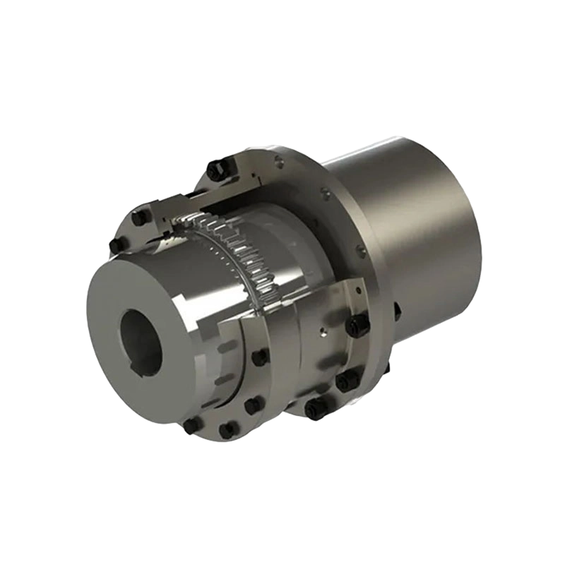
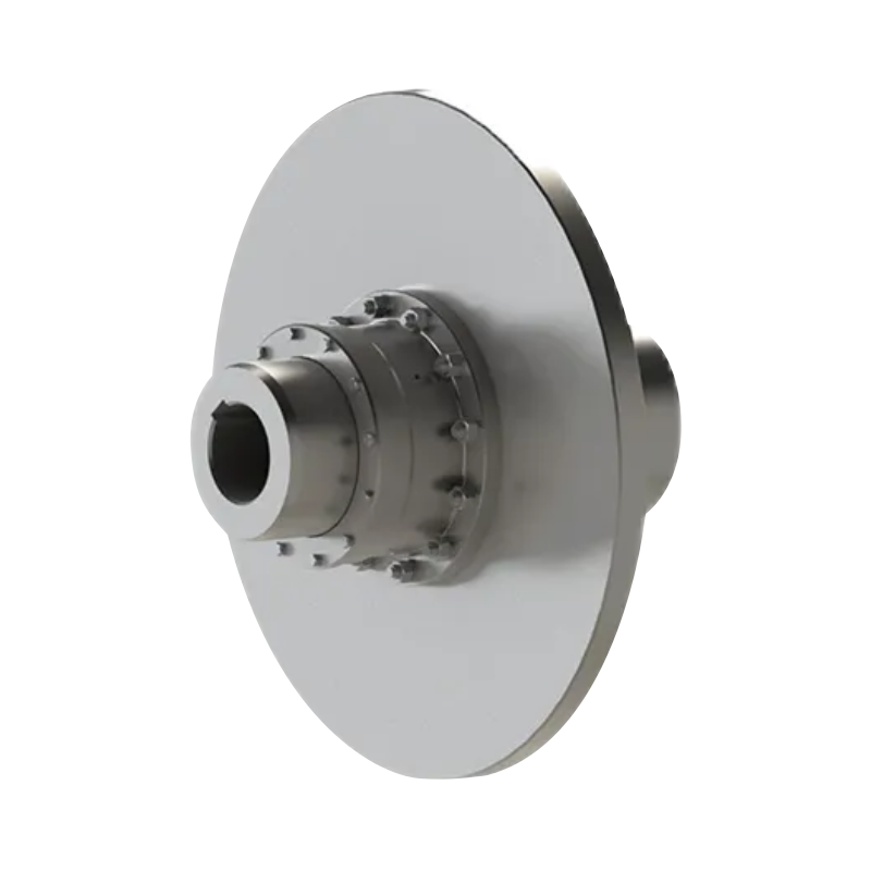
- 18 Product: SWC-BF standard expansion flange type universal coupling
Introduction
Modern industrial production depends on reliable power transmission between driving and driven machines. In steel mills, rolling lines, mining systems, marine equipment, petrochemical plants, lifting machinery, paper production lines, and other heavy-duty applications, shafts rarely operate under perfectly aligned conditions. Thermal expansion, foundation movement, installation tolerances, structural deflection, vibration, and changing operating loads can all create axial movement and angular misalignment between connected shafts. If these movements are not properly accommodated, the resulting forces can damage bearings, gears, shafts, housings, and other connected equipment.
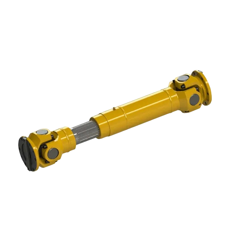
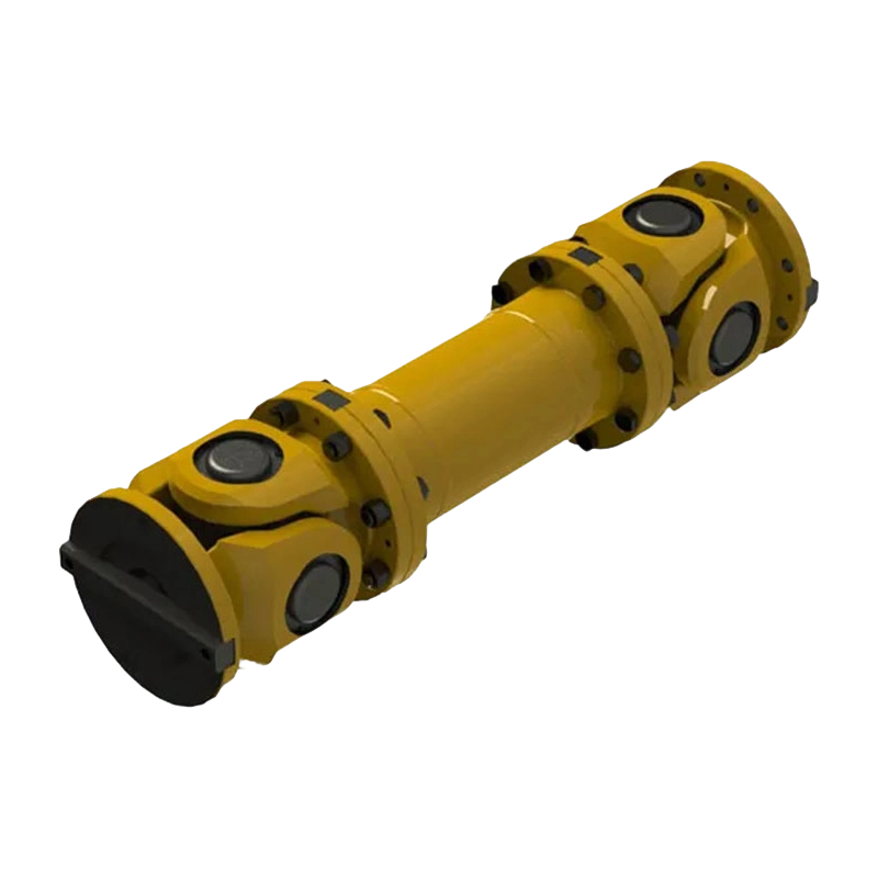
The SWC-BF standard expansion flange type universal coupling is designed for these demanding conditions. It combines a robust flange connection with a telescopic expansion structure and universal-joint articulation. The result is a non-elastic flexible coupling capable of transmitting high torque while compensating for angular deviation and axial displacement. Unlike elastic couplings that depend on rubber, polyurethane, nylon, or other flexible elements, the SWC-BF transfers torque through mechanically strong metallic components and accommodates movement through its joint and expansion arrangement.
This configuration is particularly suitable for systems in which high torque capacity, long service life, dimensional stability, and dependable operation are more important than vibration absorption through an elastic element. The design provides a practical solution for applications where shafts are separated by considerable distances, where installation conditions are difficult, or where large machinery must continue operating under heavy and fluctuating loads.
The range extends from the SWC180BF to the SWC550BF. Depending on the model, nominal torque capacity ranges from 22.4 kN·m to 1,000 kN·m, while the standard allowable axis angle is no greater than 15 degrees. Expansion and contraction capacity ranges from 100 mm to 240 mm. These characteristics make the series suitable for both medium-duty and very large industrial transmission systems.
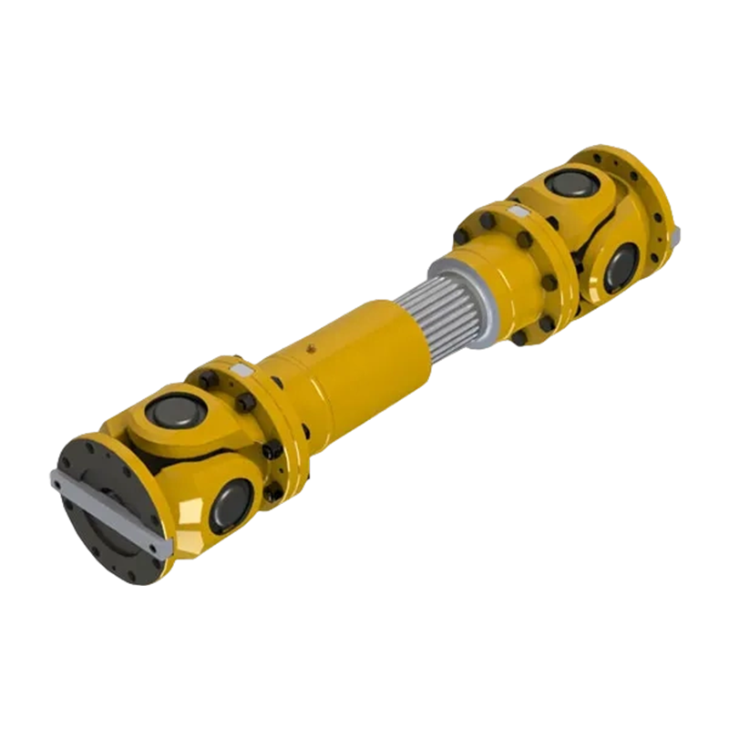
SWC-BF standard expansion flange type universal coupling
Product Overview
The SWC-BF coupling is a standard telescopic flange universal coupling. Its principal function is to connect two shafts and transmit rotary power while allowing controlled relative movement between them. The flange structure creates a strong and accurately located connection, while the telescopic section enables the coupling to absorb axial changes in the shaft arrangement. The universal-joint geometry allows the connected shafts to operate with angular deviation.
In practical installations, the coupling may be positioned between a motor, gearbox, turbine, pump, rolling stand, conveyor drive, winch, or other power source and the driven machine. The coupling does not simply act as a shaft connector. It also serves as a mechanical interface that reduces the transmission of harmful alignment forces into the connected equipment.
The standard BF configuration is built for demanding industrial service. Its heavy-duty construction is intended to withstand repeated torque transmission, rotating loads, and the mechanical stresses associated with shaft angle changes. The flange design also supports a secure connection using bolts and locating features selected for the relevant model size.
Because the coupling uses non-elastic mechanical elements, it is not dependent on a replaceable elastomeric insert for torque transmission. This can be beneficial in environments with elevated temperatures, oil exposure, metal dust, water, steam, or other conditions that may shorten the service life of polymeric elements. Proper lubrication, alignment, guarding, and inspection remain necessary, but the absence of an elastic torque-transmitting element can simplify service planning in many heavy industrial installations.
Main Functional Characteristics
The SWC-BF series provides four principal functions. First, it transmits high torque from the driving shaft to the driven shaft. Second, it compensates for angular misalignment through its universal-joint action. Third, it accommodates axial displacement through its telescopic expansion and contraction. Fourth, it provides a durable flange connection that can be integrated into a broad range of large machinery arrangements.
These functions work together. A coupling that only transmits torque but cannot accommodate misalignment may overload bearings and shafts. A coupling that compensates for movement but lacks sufficient torsional strength may suffer premature fatigue. The SWC-BF design addresses both requirements through a mechanically robust structure and a defined range of movement.
Construction and Operating Principle
Flange Connection
The flange is the primary interface between the coupling and the connected shaft assemblies. Compared with a small clamp or compact flexible-element coupling, a heavy flange connection can provide a greater load-carrying area and a secure bolted arrangement for high-torque service. Depending on the model, the flange includes multiple bolt holes, with configurations such as 8 × diameter 17 mm, 8 × diameter 19 mm, 10 × diameter 23 mm, 10 × diameter 25 mm, 16 × diameter 28 mm, or 16 × diameter 31 mm.
The flange dimensions increase as the coupling size increases. This scaling allows the connection to handle higher torque without relying on excessively small fasteners or inadequate contact areas. Correct bolt grade, tightening procedure, concentricity, and inspection are essential to obtain the designed performance.
Universal-Joint Articulation
The universal-joint portion allows the coupling to work when the two shaft centerlines are not collinear. The standard axis angle listed for the SWC-BF series is no greater than 15 degrees. This is a substantial allowance for large industrial equipment, although the actual operating angle must be evaluated according to speed, torque, duty cycle, lubrication, and the specific installation arrangement.
Angular compensation reduces the need for perfect geometric alignment between machines. However, it does not eliminate the need for careful installation. Excessive angle, uneven angle distribution, improper phasing, or high operating speed can increase bearing loads and dynamic forces. The coupling should therefore be selected and installed according to the manufacturer’s technical instructions and the complete system requirements.
Telescopic Expansion Structure
The telescopic structure enables the coupling to expand and contract in the axial direction. The standard expansion and contraction quantity is model-dependent, ranging from 100 mm for the SWC180BF to 240 mm for the SWC550BF. This movement can accommodate thermal growth, changes in the distance between connected machines, and installation or maintenance requirements.
Axial compensation is especially valuable in long transmission systems and hot-process equipment. For example, a rolling line may experience dimensional changes as machine frames heat during operation. A marine or port installation may experience movement caused by structural deformation. A large lifting or conveying machine may require axial travel during assembly or service. The telescopic section reduces the need for the connected machines to absorb these movements through their own bearings or housings.
Metallic Load-Bearing Elements
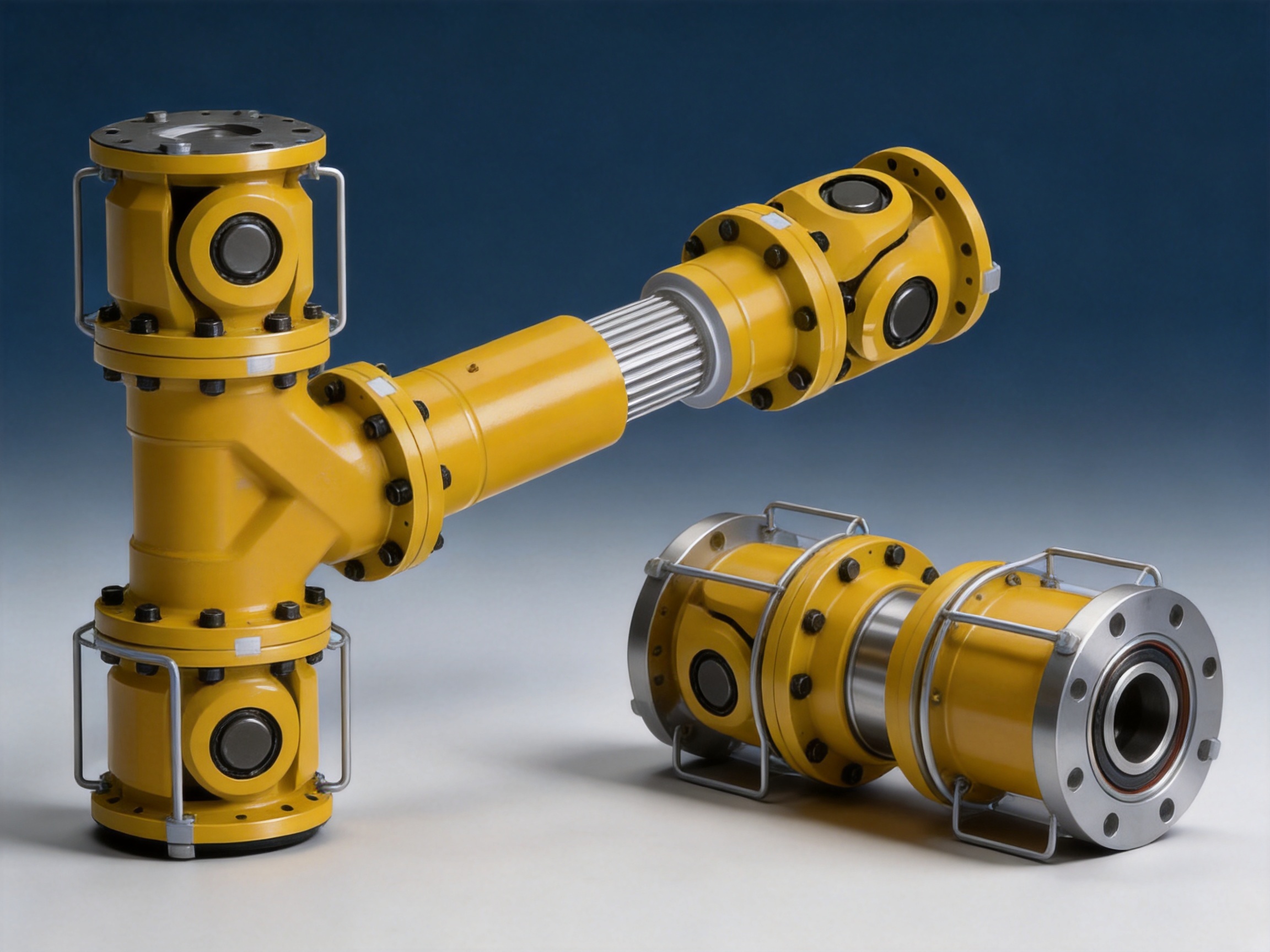
The coupling is categorized as a flexible coupling with non-elastic elements. Its torque capacity is provided by metallic structural components rather than by a rubber or polymeric element. Metallic components are appropriate for applications in which high strength, controlled geometry, and resistance to demanding mechanical duty are required.
This arrangement gives the coupling dimensional stability across a broad operating range. It also avoids the aging mechanisms associated with certain elastomers, including hardening, softening, cracking, swelling, and loss of resilience. Nevertheless, metallic components are not maintenance-free. Bearing condition, lubrication quality, fastener security, shaft fit, surface wear, and operating angle must all be monitored.
Performance Range and Technical Data
The SWC-BF family covers a wide range of coupling sizes. The rotation diameter increases from 180 mm to 550 mm, allowing the series to be matched to different shaft systems and torque requirements. Nominal torque rises progressively from 22.4 kN·m to 1,000 kN·m, while fatigue torque ranges from 11.2 kN·m to 500 kN·m.
Nominal torque is a principal selection value for normal power transmission. Fatigue torque is important when the coupling is exposed to repeated or fluctuating loading. In a real application, selection should not be based on nominal torque alone. Starting torque, shock loading, braking torque, reversing duty, speed, operating angle, service factor, ambient conditions, and the expected number of operating cycles must also be considered.
| Model | Rotation Diameter (mm) | Nominal Torque (kN·m) | Fatigue Torque (kN·m) | Maximum Axis Angle | Expansion and Contraction (mm) | Mass at Minimum Length (kg) |
|---|---|---|---|---|---|---|
| SWC180BF | 180 | 22.4 | 11.2 | 15 degrees | 100 | 80 |
| SWC200BF | 200 | 36 | 18 | 15 degrees | 110 | 109 |
| SWC225BF | 225 | 56 | 28 | 15 degrees | 140 | 138 |
| SWC250BF | 250 | 80 | 40 | 15 degrees | 140 | 196 |
| SWC285BF | 285 | 120 | 58 | 15 degrees | 140 | 295 |
| SWC315BF | 315 | 160 | 80 | 15 degrees | 140 | 428 |
| SWC350BF | 350 | 225 | 110 | 15 degrees | 150 | 582 |
| SWC390BF | 390 | 320 | 160 | 15 degrees | 170 | 817 |
| SWC440BF | 440 | 500 | 250 | 15 degrees | 190 | 1,290 |
| SWC490BF | 490 | 700 | 350 | 15 degrees | 190 | 1,721 |
| SWC550BF | 550 | 1,000 | 500 | 15 degrees | 240 | 2,567 |
The table presents selected principal values from the standard range. Detailed dimensions, bore arrangements, mounting requirements, inertia values, and mass additions for extended lengths should be confirmed for the specific project. For example, the minimum-length inertia values increase from approximately 0.267 kg·m² for the SWC180BF to approximately 86.98 kg·m² for the SWC550BF. These values are relevant to drive acceleration, braking, torsional response, and motor selection.
Dimensional Flexibility
The minimum overall length also increases with coupling size. The listed minimum lengths range from 840 mm for the SWC180BF to 2,300 mm for the SWC550BF. The coupling can be supplied with additional length, and the technical data includes mass and inertia increases for each additional 100 mm. This is useful when the distance between the drive and driven shaft cannot be accommodated by a short standard assembly.
Designers should consider the minimum and maximum installed length, the available axial travel, the required shaft overlap, the position of nearby bearings, and the space required for inspection and removal. A coupling that technically meets the torque requirement may still be unsuitable if its installed length or maintenance envelope is not compatible with the machine layout.
Advantages Compared with Alternative Coupling Types
High Torque Capacity Without an Elastic Insert
One of the main advantages of the SWC-BF is its ability to transmit substantial torque through a strong metallic structure. Many compact flexible couplings use an elastic spider, sleeve, tire, grid, or other polymeric component. These designs can provide useful damping and simple installation, but their torque rating, temperature range, and resistance to chemical exposure may be limited in severe environments.
The SWC-BF is intended for applications where torque is high and continuous mechanical strength is essential. The largest standard model has a nominal torque capacity of 1,000 kN·m and a fatigue torque value of 500 kN·m. Such capacity makes the design appropriate for large drive systems that would otherwise require an oversized elastic coupling or multiple coupling units.
Compensation for Both Angular and Axial Movement
Some rigid couplings provide excellent torsional stiffness but cannot tolerate meaningful shaft misalignment. Other compact flexible couplings compensate for limited angular or parallel offset but have little axial travel. The SWC-BF combines universal-joint angular compensation with telescopic axial movement. This combination is valuable in long, large, or thermally active machine arrangements.
The ability to accommodate movement can reduce secondary forces on connected equipment. Lower secondary loading may help protect bearings, reduce housing stress, and maintain more stable machine operation. It can also simplify the connection of equipment that cannot be positioned with perfect precision during every operating condition.
Suitability for Severe Industrial Environments
Heavy machinery frequently operates in conditions involving heat, dust, water, scale, vibration, shock, and oil contamination. A metallic universal coupling does not rely on an exposed elastomeric element to maintain its torque-transmitting function. This can offer a practical advantage where the environment is unsuitable for conventional polymer components.
Environmental suitability still depends on the complete design. Seals, lubrication, surface protection, guarding, and material selection must be appropriate for the installation. The coupling should not be treated as immune to corrosion, abrasive particles, or poor maintenance. Its advantage is that the core load-bearing principle is based on durable mechanical components suited to heavy service.
Long Service Potential
When correctly selected, installed, lubricated, and maintained, a heavy-duty universal coupling can provide a long operating life. Its metallic construction supports stable dimensions and avoids routine replacement of elastomeric torque elements. This can reduce planned downtime and lower the risk of unexpected stoppages caused by deteriorated flexible inserts.
Service life is influenced by fatigue torque, operating angle, speed, shock loading, lubrication, balance, shaft alignment, and maintenance quality. The coupling should be selected with a suitable margin rather than operated continuously at the upper limit of its published rating.
Broad Application Range
The SWC-BF series is available in eleven standard sizes, covering a wide torque range. This allows engineers to use a consistent design concept across different sections of a plant or across related equipment platforms. Standardization can simplify spare-parts planning, staff training, inspection procedures, and procurement.
Where the standard range does not exactly match the project requirements, a manufacturer with non-standard design capability can adapt shaft bores, lengths, flange details, protection arrangements, materials, and other parameters subject to engineering review. This is especially important in replacement projects where the existing machine foundation cannot be modified easily.
Application Areas
Metallurgical and Steel Equipment
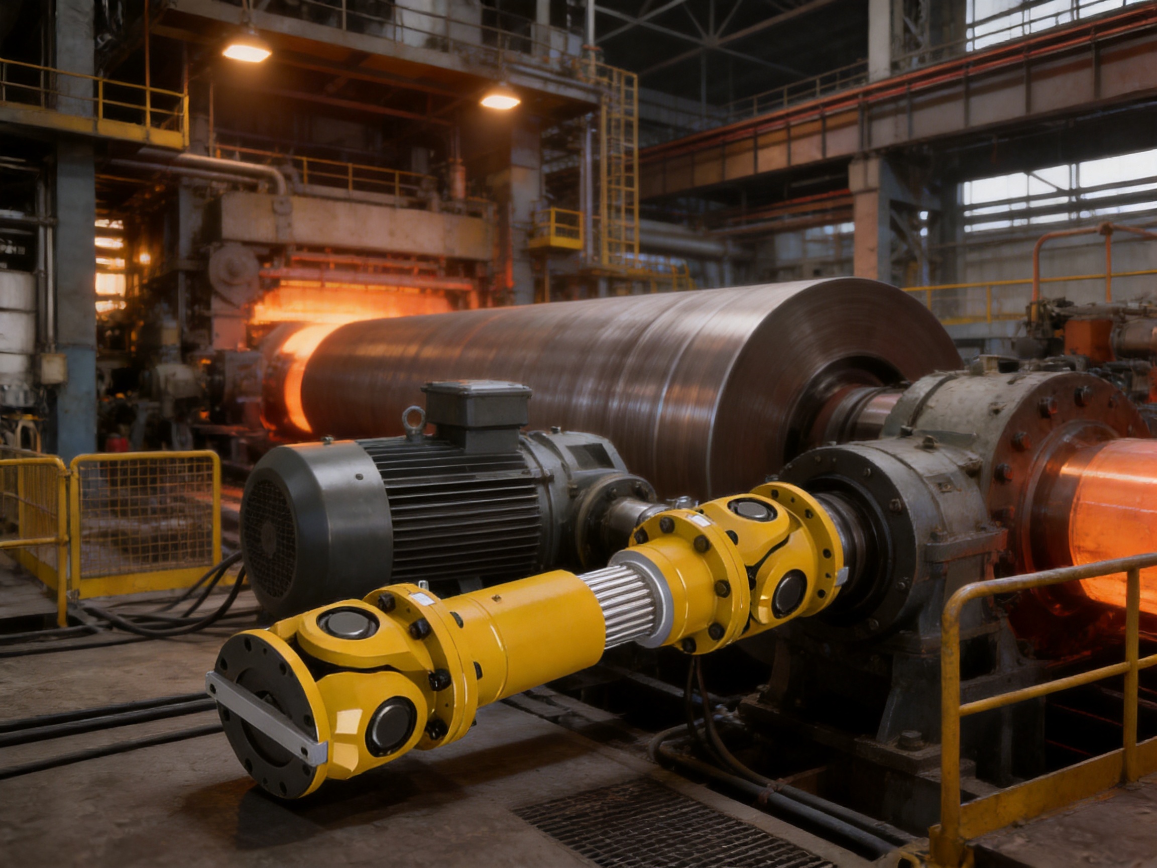
Steel production and metal-processing equipment often combines high torque, shock loading, heat, scale, and frequent starting or reversing. Rolling mills, straightening machines, transfer equipment, shears, cooling-bed drives, and other metallurgical systems can benefit from a coupling that tolerates shaft movement while maintaining reliable power transmission.
Thermal expansion is a common concern in hot-process equipment. The telescopic section can accommodate changes in shaft spacing caused by heating, cooling, or structural movement. The robust flange connection is also appropriate for large shafts and high-torque drives found in primary and secondary steel-processing lines.
Mining and Bulk Material Handling
Mining equipment may operate under heavy shock loads, dust, vibration, and variable material flow. Crushers, conveyors, bucket elevators, stackers, reclaimers, hoists, and processing machinery require durable drive components. The SWC-BF can be considered where a high-torque connection with angular and axial compensation is required.
In mining service, protection against contamination is essential. The coupling should be fitted with a suitable guard and maintained according to an inspection schedule that accounts for dust ingress, lubricant condition, fastener loosening, and wear at moving interfaces.
Marine and Port Machinery
Marine propulsion auxiliaries, deck machinery, ship loaders, unloaders, cranes, winches, and port conveyors may experience structural deflection and changing shaft alignment. A telescopic universal coupling can help manage movement between drive units and driven equipment while preserving a strong torque path.
Marine and coastal applications require careful attention to corrosion protection, sealing, lubrication, and material compatibility. The coupling selection should reflect salt exposure, humidity, maintenance access, and the consequences of equipment downtime.
Petrochemical and Process Equipment
Petrochemical plants and process facilities use pumps, compressors, mixers, conveyors, and specialized rotating systems. Depending on the machine arrangement, axial expansion and angular deviation may occur as equipment reaches operating temperature. The SWC-BF can support a mechanically stable connection in installations where an elastic element may not be the preferred solution.
Hazardous-area requirements, guarding, surface temperature, material certificates, and plant-specific safety procedures must be addressed independently. The coupling should be incorporated into a complete machinery safety design rather than evaluated as an isolated component.
Lifting and Heavy Machinery
Cranes, hoists, transfer cars, lifting platforms, and large handling machines often experience variable loads and repeated starts and stops. The coupling must withstand acceleration torque, braking torque, and potential shock conditions. A universal coupling with high fatigue capacity can be advantageous when the drive train requires both flexibility and mechanical strength.
Paper, Water, and General Industrial Equipment
Paper machinery, water equipment, pumps, fans, mixers, and other industrial systems may require reliable torque transmission across a relatively long shaft arrangement. The standard SWC-BF range provides multiple size options, while customized engineering can address special bore, length, or mounting requirements.
Engineering Selection Guidelines
Determine the Required Torque
The first step is to calculate the actual transmitted torque. For a known power and speed, the operating torque can be estimated using the relationship between power, rotational speed, and torque. The result must then be multiplied by appropriate service factors for starting, stopping, impact, reversing, cyclic operation, and load variation.
Nominal torque should exceed the calculated design torque. If the machinery has frequent shock loading or severe cyclic duty, fatigue torque becomes equally important. The SWC-BF should not be selected solely because its nominal torque is higher than the motor’s steady-state output.
Evaluate Angular Misalignment
The installation angle between the connected shafts must be measured or calculated. The standard maximum axis angle is no greater than 15 degrees, but the preferred operating angle may be lower depending on speed and duty. Larger angles can increase joint motion, bearing loads, and dynamic forces.
Engineers should also consider whether the angle is constant or changes during operation. A machine that moves through a range of positions may impose a varying angle on the coupling. The most severe operating position should be included in the calculation.
Calculate Axial Movement
The required expansion and contraction must include thermal growth, structural movement, installation tolerance, and any planned machine adjustment. The available telescopic capacity must be greater than the total expected movement, with an appropriate reserve to prevent the coupling from reaching its mechanical limit.
It is important to distinguish between total available expansion and the recommended operating range. The coupling should not remain permanently at the end of its travel. Adequate positioning during installation allows the telescopic section to move in both directions as the equipment changes condition.
Check Speed and Dynamic Behavior
Rotation speed, balance, shaft length, coupling inertia, and operating angle influence dynamic behavior. Larger couplings have greater inertia, which affects motor acceleration and braking. The listed minimum-length inertia and the increase per additional 100 mm should be considered during drive-system analysis.
For high-speed applications, balancing requirements and critical-speed separation must be evaluated. The universal-joint arrangement should be installed with correct phasing, and the complete rotating assembly should be checked for vibration after commissioning.
Review Shaft and Flange Dimensions
Shaft diameter, bore tolerance, keyway or spline arrangement, hub length, flange diameter, bolt-circle dimensions, and available installation space must all be verified. The technical table identifies key dimensional categories such as rotation diameter, D1, D2, D3, minimum length, bolt configuration, and flange-related dimensions.
When replacing an existing coupling, the replacement should be checked against the actual shaft ends and machine interfaces. A nominally equivalent model may require an adapter, modified bore, revised spacer length, or different fastener arrangement. Such changes should be reviewed by qualified engineering personnel.
Manufacturing Process and Quality Strengths
Integrated Research, Development, and Production
The manufacturer operates as an integrated research, manufacturing, and sales enterprise. This structure supports communication between design engineers, production personnel, quality teams, and application specialists. For a specialized coupling, this integration is important because product performance depends on the relationship between design geometry, material selection, machining accuracy, assembly quality, lubrication, and installation conditions.
An integrated technical team can review customer drawings, operating data, existing equipment interfaces, and special environmental requirements before recommending a product. This reduces the risk of selecting a coupling based only on a catalog torque value without considering the complete mechanical system.
Heavy and Precision Workshop Capabilities
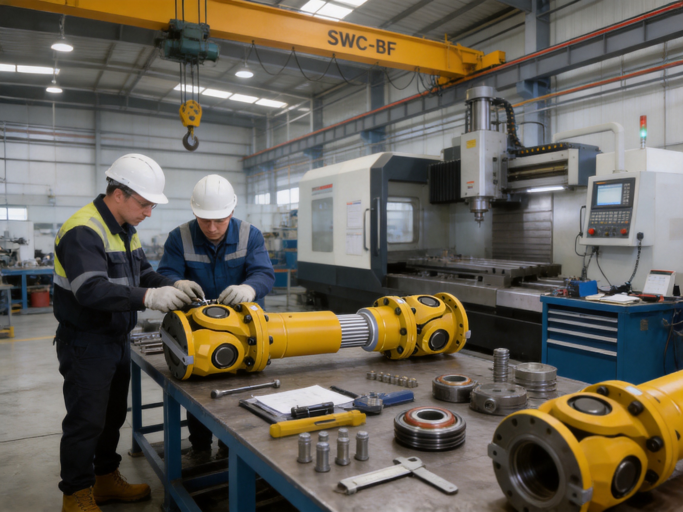
The company’s new workshop covers approximately 16,463.52 square meters. It includes a heavy workshop of approximately 5,500 square meters, a precision workshop of approximately 4,600 square meters, an office building and gymnasium, a dining facility, a warehouse, and supporting roads and green areas.
The combination of heavy and precision production areas is particularly relevant to large universal couplings. Heavy equipment and handling capacity are needed for large forgings, castings, shafts, flanges, and assembled couplings. Precision machining capability is required for bores, locating surfaces, bearing seats, flange interfaces, telescopic components, and rotating-part geometry.
Process Control from Raw Material to Assembly
A reliable manufacturing process begins with controlled raw materials and documented technical requirements. Material selection should correspond to the expected torque, fatigue duty, environmental exposure, wear conditions, and heat-treatment requirements. Incoming inspection, traceability, and conformity checks help ensure that materials are suitable before machining begins.
Heavy components can then undergo turning, boring, milling, drilling, keyway or spline machining, heat treatment where specified, grinding or finishing of critical surfaces, and dimensional verification. Each process must preserve concentricity and the relationship between the rotational centerline and the flange or bore features.
Assembly is equally important. Bearings, joints, telescopic interfaces, fasteners, seals, and lubrication passages must be installed according to controlled procedures. Incorrect assembly can cause premature wear even when individual components meet their dimensional requirements. Final inspection should verify rotation, movement, fit, fastening, lubrication, and overall appearance.
Testing and Inspection
The manufacturer emphasizes advanced testing facilities and strict quality control. For a large coupling, relevant quality activities may include dimensional inspection, material verification, hardness checks where required, non-destructive examination of critical parts, balance checks, rotation testing, and functional verification of telescopic and angular movement.
Inspection records provide evidence that the coupling conforms to the approved design. Depending on project requirements, documentation may include material certificates, dimensional reports, inspection plans, balancing records, assembly records, and product identification information. Clear documentation is especially valuable for large industrial projects with formal quality-assurance procedures.
Standards and Certification Orientation
The company states that its products comply with international standards and certifications such as ISO 9001. A quality-management system supports consistent procedures for design control, purchasing, production, inspection, corrective action, and customer service. The exact standards and certificates applicable to a particular coupling should be confirmed during project specification and quotation.
Standards compliance does not replace engineering judgment. The operating conditions, safety requirements, and acceptance criteria for each project should be defined clearly. A qualified manufacturer can help identify the relevant technical documents and inspection requirements before production.
Customization and Non-Standard Engineering
Industrial machinery often includes unique shaft positions, restricted maintenance spaces, unusual bore sizes, special flange patterns, or unusual environmental requirements. The manufacturer provides design and manufacturing support for non-standard couplings, allowing the SWC-BF concept to be adapted to particular equipment.
Potential customization areas may include overall length, shaft bore, keyway or spline configuration, flange dimensions, bolt-hole pattern, material grade, surface treatment, sealing, lubrication arrangement, protective guard, balancing level, and connection accessories. Every modification must be assessed for its effect on torque capacity, fatigue life, stiffness, mass, inertia, and dynamic behavior.
For a custom project, the customer should provide as much information as possible. Useful data includes transmitted power, operating speed, starting method, peak torque, reversing frequency, shaft diameters, shaft-end drawings, shaft distance, expected angular deviation, axial movement, ambient temperature, contaminants, duty cycle, installation orientation, maintenance constraints, and applicable standards.
The manufacturer can then create a technical proposal and, where appropriate, a detailed drawing for approval. Drawing approval before production helps confirm that the coupling will fit the existing equipment and that the installation team understands the required interfaces.
Installation Recommendations
Before installation, inspect the coupling and compare its dimensions with the approved drawing. Confirm that the shaft ends, bores, keys, splines, bolts, guards, and support arrangements are clean and undamaged. Check that the telescopic section has the correct initial position and that sufficient axial travel remains available in both directions.
Do not force the coupling onto a shaft by striking the flange or another precision surface. Use suitable lifting and fitting equipment for the coupling mass. The largest SWC-BF model has a listed minimum-length mass of approximately 2,567 kg, so lifting plans, certified equipment, and exclusion zones are essential.
Align the coupling according to the required angular and axial geometry. Although the coupling compensates for misalignment, intentional installation beyond the design limits can create excessive loads. Verify the relationship between the connected shafts, the coupling angle, and the available telescopic movement.
Install bolts using the specified grade and tightening sequence. Apply the required torque and use appropriate locking methods where specified. After assembly, rotate the system manually if possible to check for interference, binding, abnormal resistance, or insufficient clearance.
Install a suitable guard before operation. The universal-joint and telescopic sections contain rotating and moving parts that can present serious hazards. The guard should prevent access to rotating components while allowing appropriate inspection and lubrication procedures.
Maintenance and Service
Maintenance requirements depend on operating conditions, but regular inspection should be part of the equipment-management program. Inspect for unusual noise, vibration, heat, lubricant leakage, loose fasteners, corrosion, surface damage, wear, and changes in telescopic movement. Any sudden change in operating behavior should be investigated before continued operation.
Lubrication must follow the specified lubricant type, quantity, and interval. Over-lubrication can be as problematic as under-lubrication if it causes heat generation, seal damage, or contamination. In dusty or wet environments, lubrication intervals may need adjustment based on actual service conditions.
Check the coupling after major maintenance on the connected equipment. Moving a motor, gearbox, bearing housing, or driven machine can change the angular and axial relationship. The coupling should be inspected after foundation work, bearing replacement, shaft repair, severe overload, or any event that may have affected alignment.
During planned shutdowns, examine bearing areas, joint components, telescopic surfaces, flange bolts, shaft fits, keys, splines, and guards. Look for fretting, pitting, cracks, abnormal polishing, looseness, or deformation. Components that show damage should be assessed by qualified personnel before the machine is returned to service.
Operational and Economic Benefits
Reliable coupling performance contributes to overall plant productivity. When shaft misalignment and axial movement are accommodated within the coupling, connected bearings and housings may experience lower unwanted loads. This can reduce unplanned repairs and help maintain stable machine operation.
The absence of a polymeric torque element may reduce the frequency of replacement associated with elastomer aging. In high-temperature, oil-contaminated, or abrasive environments, this can support more predictable maintenance planning. The actual economic result depends on correct selection and maintenance, but the heavy-duty mechanical design is intended to support long-term service.
Standardized model selection can also simplify spare-parts management. A plant using several sizes from the same product family may establish common inspection methods, lubrication practices, and training materials. The availability of customization further reduces the need for extensive modification of existing machinery.
Lower downtime is often more valuable than the initial component price. A coupling that is easy to install, supported by technical documentation, and matched accurately to the machine can reduce commissioning delays and shorten future maintenance work. The manufacturer’s pre-sale engineering support and after-sale service are therefore important parts of the total product value.
Why Choose a Specialized Coupling Manufacturer
A universal coupling for heavy equipment is not a generic commodity component. Its performance depends on geometry, materials, machining, balancing, assembly, and application support. A specialized manufacturer with experience in toothed couplings, elastic pin couplings, universal couplings, tire couplings, jaw couplings, diaphragm couplings, drum couplings, grid couplings, flange couplings, and other transmission products can draw on broad technical experience when evaluating a project.
The manufacturer described in the supplied information serves metallurgical equipment, mining equipment, water equipment, lifting equipment, paper equipment, port equipment, and other industries. This application range indicates familiarity with different load patterns, installation conditions, and maintenance requirements.
Its stated strengths include research and development capability, manufacturing capacity, testing facilities, quality control, complete product specifications, customization support, transmission efficiency, technical consultation, non-standard design, and after-sales service. These capabilities are useful when a customer requires more than a catalog selection.
Technical communication is particularly important for large couplings. The correct product may depend on a detail such as a short-duration peak torque, a limited installation length, a non-standard shaft bore, a variable operating angle, or the need for a special corrosion-protection system. A manufacturer that can review these details can help reduce design risk.
Comparison with Nylon and Other Flexible Couplings
Nylon gear couplings, nylon sleeve gear couplings, nylon inner gear couplings, and flexible nylon gear couplings can be useful where compact size, moderate torque, simple installation, and some flexibility are required. They are often considered for general machinery and applications in which the operating temperature, chemical exposure, and load severity are within the capability of the nylon element.
The SWC-BF occupies a different performance category. It is intended for larger, heavier, and more demanding systems where telescopic axial compensation, substantial angular movement, and very high torque are required. Its size and mass are greater than those of many compact nylon couplings, but that construction supports a different class of industrial duty.
Selection should therefore be based on engineering requirements rather than on a simple preference for one coupling type. A nylon gear coupling may be efficient for a moderate-duty drive, while an SWC-BF may be more appropriate for a high-torque rolling line or heavy transfer machine. The best solution is the one that meets the torque, movement, speed, environment, maintenance, and safety requirements of the complete system.
Q&A
What is the SWC-BF coupling designed to do?
The SWC-BF is designed to transmit torque between two shafts while compensating for angular misalignment and axial displacement. Its flange structure provides a strong mechanical connection, its universal-joint arrangement accommodates angular deviation, and its telescopic section allows expansion and contraction.
Is the SWC-BF an elastic coupling?
No. It is a flexible coupling with non-elastic elements. It provides flexibility through mechanical articulation and telescopic movement rather than through a rubber, nylon, polyurethane, or other elastic torque-transmitting element.
What is the largest standard model?
The largest listed standard model is the SWC550BF. It has a 550 mm rotation diameter, a nominal torque of 1,000 kN·m, a fatigue torque of 500 kN·m, a standard axis angle of no greater than 15 degrees, and an expansion and contraction quantity of 240 mm.
What is the allowable angular deviation?
The standard technical data lists an axis angle of no greater than 15 degrees for the SWC-BF range. The actual recommended operating angle should be evaluated according to speed, torque, duty cycle, lubrication, and the specific machine arrangement.
How much axial movement can the coupling accommodate?
Capacity depends on the model. The listed expansion and contraction values range from 100 mm for the SWC180BF to 240 mm for the SWC550BF. The required operating position should leave sufficient reserve travel in both directions.
Can the coupling be used in high-temperature equipment?
It can be considered for high-temperature industrial equipment because its core torque-transmitting components are metallic rather than polymeric. However, the complete design must address lubricant selection, seals, material properties, thermal expansion, guarding, and the actual temperature at the coupling.
Can the standard coupling be customized?
Customization is available for non-standard applications subject to engineering review. Possible changes may include length, bore, flange dimensions, bolt arrangement, materials, surface treatment, sealing, lubrication, balancing, and protective accessories.
What information is needed for product selection?
Important information includes transmitted power, speed, nominal and peak torque, starting and braking conditions, duty cycle, shaft diameter, shaft distance, angular misalignment, axial movement, environmental conditions, installation orientation, and applicable technical standards. Shaft drawings and equipment layout drawings are also helpful.
Does the coupling require maintenance?
Yes. Although it does not use an elastic insert that requires periodic replacement, it still requires inspection, lubrication, fastener checks, alignment verification, and examination of bearings, joints, telescopic surfaces, shafts, and guards.
Why is coupling mass important?
Large couplings have significant inertia. Mass and moment of inertia affect motor acceleration, braking, torsional response, and the dynamic behavior of the drive system. The coupling should therefore be evaluated as part of the complete rotating assembly.
Where is the SWC-BF commonly used?
Typical applications include metallurgy, steel processing, mining, port machinery, marine equipment, petrochemical equipment, lifting machinery, paper machinery, water equipment, conveyors, and other heavy industrial systems requiring high torque and movement compensation.
How does the product compare with a rigid flange coupling?
A rigid flange coupling is intended for accurately aligned shafts and does not normally accommodate significant angular or axial movement. The SWC-BF uses a flange connection but adds universal-joint articulation and telescopic movement, making it suitable for installations where shaft movement must be controlled.
Conclusion
The SWC-BF standard expansion flange universal coupling is a heavy-duty solution for industrial drive systems that require high torque transmission together with angular and axial compensation. Its non-elastic mechanical construction, telescopic structure, universal-joint action, and robust flange connection distinguish it from smaller elastic or rigid coupling designs.
With eleven standard models, nominal torque capacity from 22.4 kN·m to 1,000 kN·m, fatigue torque up to 500 kN·m, and expansion and contraction capacity up to 240 mm, the series can address a broad range of machinery requirements. Its application value is particularly strong in metallurgical, mining, marine, port, petrochemical, lifting, paper, water, and other heavy industrial environments.
The product’s performance depends on proper engineering selection, accurate installation, effective lubrication, suitable guarding, and planned inspection. The manufacturer’s integrated research, production, quality-control, customization, and service capabilities support customers from initial design through operation and maintenance.
For equipment owners and engineering contractors, the main benefit is not simply a high catalog torque rating. It is the combination of mechanical strength, movement compensation, dimensional flexibility, industrial experience, manufacturing resources, and technical support. When these factors are matched carefully to the operating conditions, the SWC-BF can contribute to dependable power transmission, reduced secondary loading, longer equipment life, and lower lifecycle maintenance risk.
References
1. Supplied technical specification: BF Standard Expansion Flange Universal Coupling Basic Parameters and Main Dimensions.
2. Supplied product information for the SWC-BF standard expansion flange type universal coupling.
3. Supplied company information regarding research and development, manufacturing facilities, quality control, testing, customization, and industrial applications.
4. General engineering principles for the selection, installation, lubrication, inspection, and maintenance of universal shaft couplings.
5. General industrial practice for torque, fatigue loading, angular misalignment, axial displacement, rotating inertia, and coupling safety guarding.
Product: SWC-BF standard expansion flange type universal coupling
- Quick Links
- About
- Products
- Our Service
- News & Events
- Contact
- Products Series
- Flexible Couplings with Non-Elastic Elements
- Flexible Couplings with Metal Elastic Elements
- Flexible Couplings with Non-Metallic Elastic Elements
- Safety Coupling
- Rigid Coupling
- Contact Us
- Tel : +86 511 8572 3800 +86 511 8572 3900
- Mobile : +86 15106109009
- Email : sales@couplingzy.com
- Add:No.1 Zhongye Yingbin Avenue, Gaozi Street, Dantu Economic Development Zone, Zhenjiang City, Jiangsu Province, China.


