:+86 15106109009
:sales@couplingzy.com


 English
  русский
  Español
  عربى
عربى  Português
  Deutsch
  Türk
Türk  Indonesia

GB Drum Gear Coupling: High-Capacity Power Transmission for Demanding Industrial Systems
Content
- 1 1. Product Definition and Operating Principle
- 2 2. Main Performance Range
- 3 3. Technical Characteristics of the GB Series
- 4 4. Dimensional and Mechanical Data
- 5 5. Advantages Compared with Other Coupling Solutions
- 6 6. Manufacturing Process and Engineering Quality
- 7 7. Manufacturing Facilities and Organizational Strengths
- 8 8. Industrial Applications
- 9 9. Environmental Adaptability and Corrosion Protection
- 10 10. Lubrication and Maintenance
- 11 11. Installation Recommendations
- 12 12. Coupling Selection Procedure
- 13 13. Customization and Non-Standard Design
- 14 14. Reliability, Service Life, and Total Cost
- 15 15. Why Work with an Experienced Coupling Manufacturer?
- 16 16. Practical Advantages Summary
- 17 17. Q&A
- 17.1 Q1: What type of coupling is the GB product?
- 17.2 Q2: What standard does the product follow?
- 17.3 Q3: What is the torque range of the GB series?
- 17.4 Q4: What is the maximum allowable speed?
- 17.5 Q5: What shaft diameters can the coupling accommodate?
- 17.6 Q6: Can the coupling compensate for shaft misalignment?
- 17.7 Q7: Is the GB coupling suitable for shock loads?
- 17.8 Q8: Does the coupling require lubrication?
- 17.9 Q9: Can the product be used outdoors?
- 17.10 Q10: Is the GB series suitable for rolling mills?
- 17.11 Q11: Can the manufacturer provide customized couplings?
- 17.12 Q12: What information should be supplied for a quotation?
- 17.13 Q13: How should large GB couplings be installed?
- 17.14 Q14: What are the main causes of premature coupling failure?
- 17.15 Q15: Does a gear coupling provide torsional vibration damping?
- 18 18. Conclusion
- 19 References
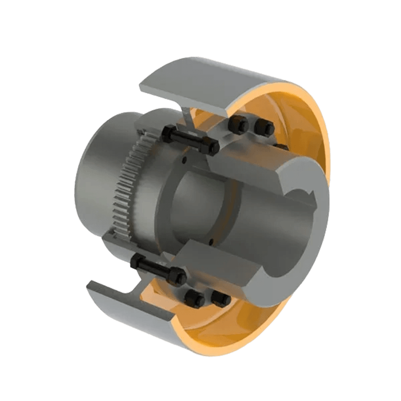
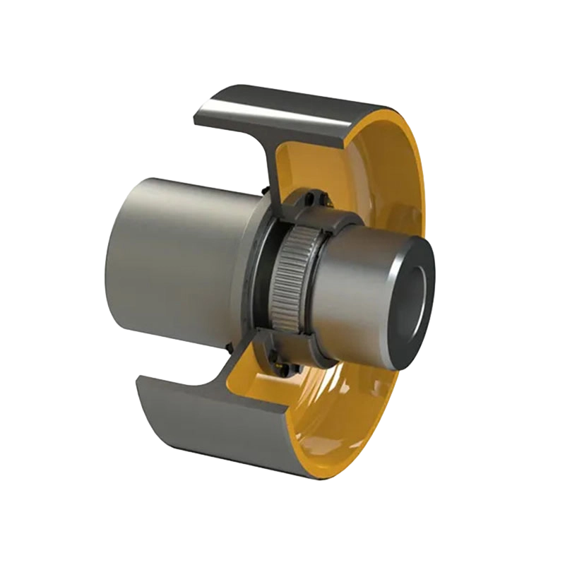
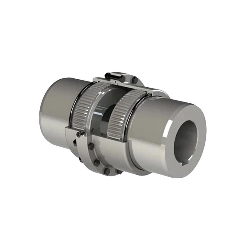
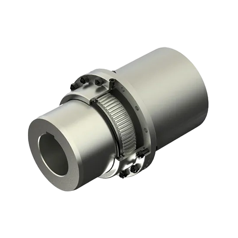
- 20 Product: GB Drum gear coupling(Q/YG11001X-2018)
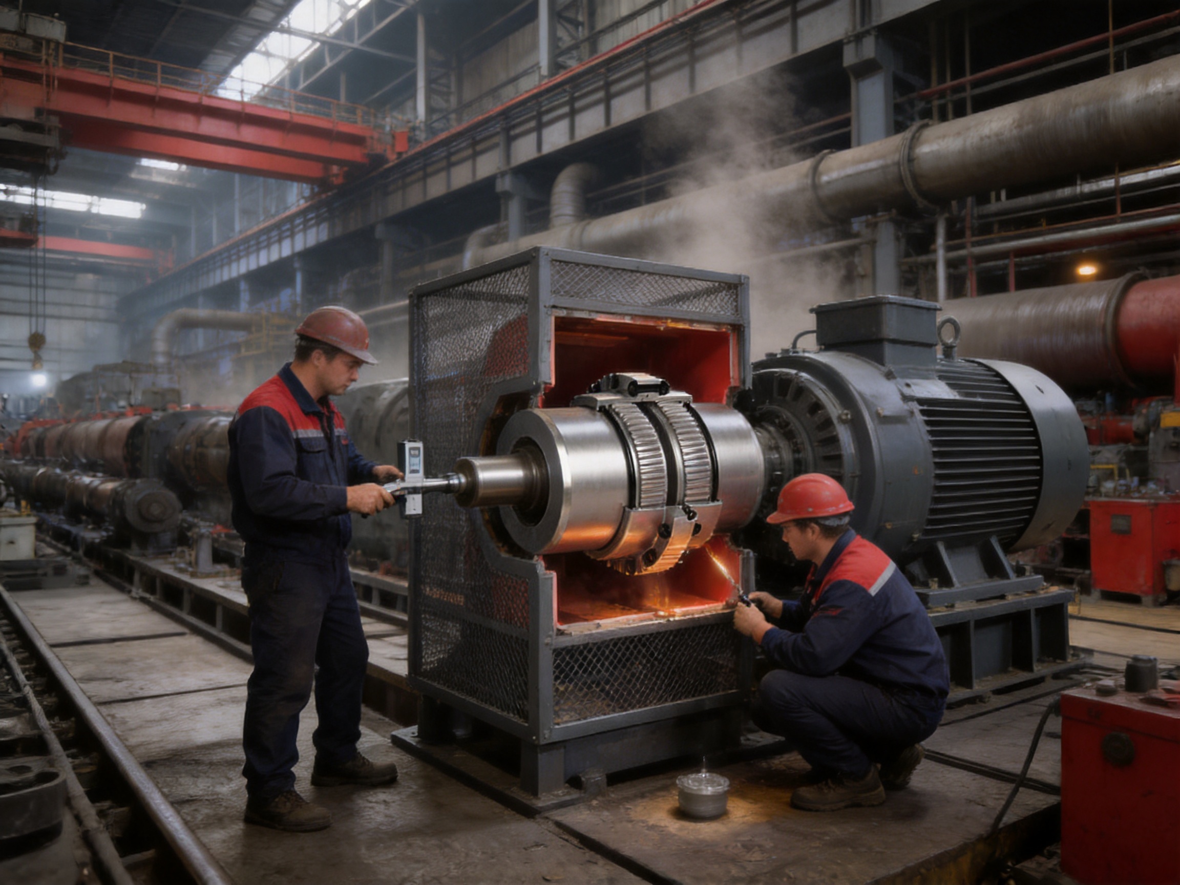
Industrial transmission systems increasingly require couplings that can handle high torque, fluctuating loads, shaft misalignment, vibration, contamination, and long operating cycles without frequent interruption. In heavy machinery, the coupling is not merely a connecting component between two shafts. It is a critical mechanical interface that determines how effectively power is transmitted, how well shock loads are absorbed, and how reliably connected equipment operates under changing conditions.
The GB-type drum gear coupling, manufactured according to Q/YG11001X-2018, is designed for precisely these demanding requirements. It belongs to the category of flexible couplings with non-elastic elements and uses a drum-shaped gear tooth arrangement to transmit torque while accommodating a degree of angular misalignment between connected shafts. The product range extends from compact GB1 models for smaller equipment to extremely large GB25 models for ultra-heavy industrial machinery.
With nominal torque ratings from 0.63 kN·m to 5,600 kN·m, allowable speeds from 420 r/min to 6,500 r/min, and shaft-hole diameters from 16 mm to 1,040 mm, the series provides a broad selection for different equipment sizes and operating conditions. It is suitable for metallurgical machinery, mining equipment, cranes, conveyors, pumps, compressors, paper machinery, port equipment, and other systems in which dependable torque transmission is essential.
The coupling is produced by Zhongye Heavy Industry Technology (Zhenjiang) Co., Ltd., a specialist manufacturer integrating research and development, manufacturing, sales, technical support, and after-sales service. The company provides standard products as well as non-standard coupling design and manufacturing services for applications requiring special dimensions, load conditions, materials, or installation arrangements.
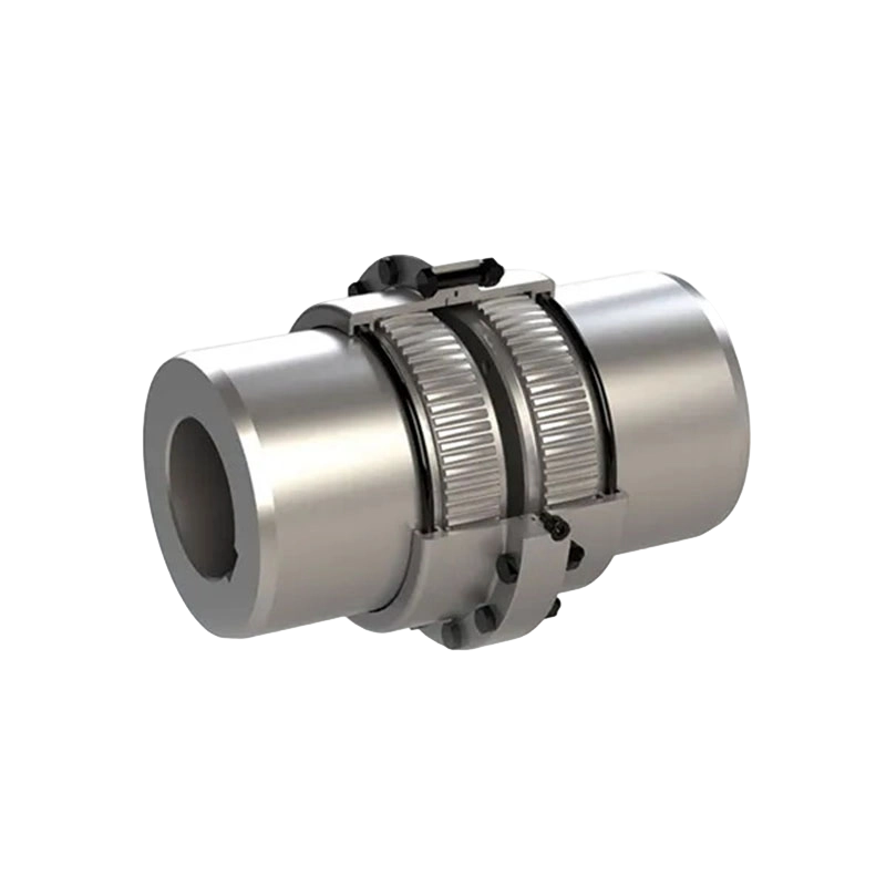
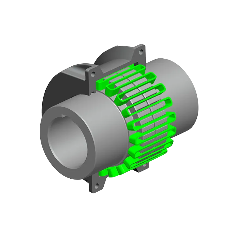
GB Drum gear coupling(Q/YG11001X-2018)
1. Product Definition and Operating Principle
A gear coupling transmits torque through the engagement of external and internal gear teeth. In a conventional straight-tooth design, the tooth flanks are generally cylindrical or parallel to the shaft axis. A drum gear coupling modifies this arrangement by using curved or crowned tooth geometry. The crowned profile allows the coupling to maintain more favorable tooth contact when the connected shafts are not perfectly collinear.
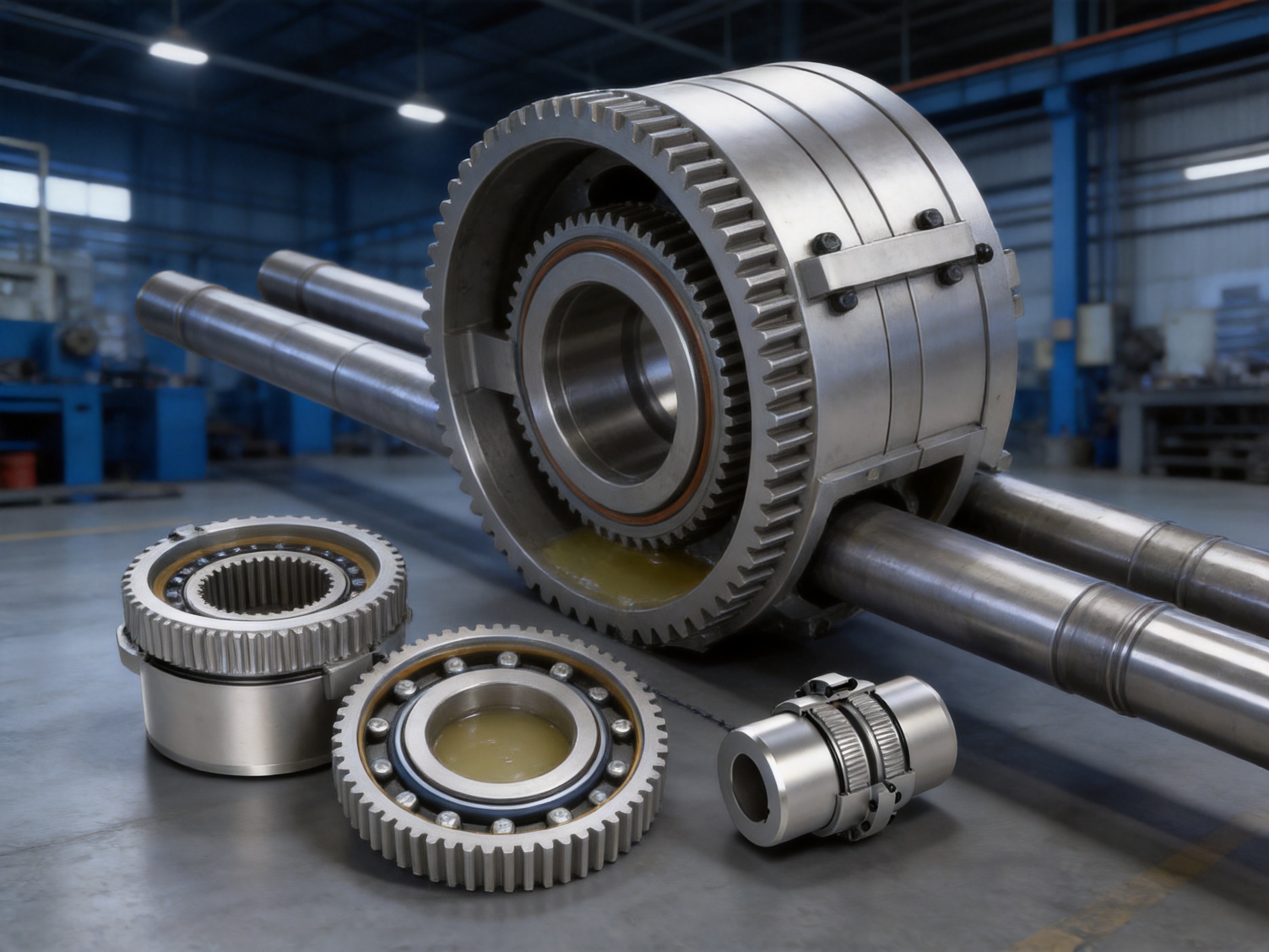
The GB drum gear coupling normally consists of gear sleeves, hubs, sealing elements, fasteners, and a grease-filled internal cavity. The hubs are mounted on the drive and driven shafts. Their external teeth engage with the internal teeth of the sleeves. When the driving shaft rotates, torque passes through the hub teeth, into the sleeve, and then to the driven hub and shaft.
The drum-shaped tooth profile provides flexibility through controlled tooth contact rather than through a rubber, polymer, or metallic spring element. This is why the product is categorized as a flexible coupling with a non-elastic element. It does not depend on an elastomeric insert to transmit torque, and it does not use a separate spring pack or diaphragm as its primary flexible component.
The flexible movement available in the coupling is intended to compensate for allowable angular misalignment and certain installation deviations. This can help reduce excessive edge loading, improve the stability of the connected shafts, and protect bearings and other transmission components from avoidable reaction forces. The actual allowable misalignment depends on the selected model, operating speed, lubrication condition, load, and installation accuracy.
Because the torque is transmitted through multiple gear teeth, the load is distributed over a substantial contact area. This makes the coupling suitable for applications where high torque density, compact installation, and resistance to impact are more important than the vibration isolation provided by an elastic coupling.
2. Main Performance Range
The GB series covers 25 model sizes, from GB1 through GB25. The smallest models are intended for relatively compact equipment and high-speed applications. The largest models are designed for low-speed, high-torque systems such as heavy rolling equipment, large hoisting mechanisms, and other major industrial drives.
| Model Range | Nominal Torque | Allowable Speed Range | Shaft-Hole Diameter Range | Typical Equipment Scale |
|---|---|---|---|---|
| GB1–GB4 | 0.63–2.8 kN·m | 5,100–6,500 r/min | 16–65 mm | Compact machinery and precision transmission equipment |
| GB5–GB8 | 4.5–11.2 kN·m | 3,700–4,600 r/min | 40–115 mm | General industrial drives and medium-duty equipment |
| GB9–GB13 | 18–80 kN·m | 2,200–3,350 r/min | 60–225 mm | Heavy pumps, conveyors, cranes, and process machinery |
| GB14–GB18 | 125–550 kN·m | 1,210–2,000 r/min | 170–400 mm | Large metallurgical and lifting equipment |
| GB19–GB22 | 800–2,000 kN·m | 700–1,050 r/min | 300–680 mm | Large-scale heavy-duty industrial transmission |
| GB23–GB25 | 2,800–5,600 kN·m | 420–610 r/min | 530–1,040 mm | Ultra-heavy equipment and low-speed high-torque systems |
The range is valuable for equipment designers because it allows a common coupling concept to be applied across several machine sizes. A plant may use smaller GB models on auxiliary drives and larger models on main drives while maintaining familiarity with the same general construction, inspection principles, and lubrication requirements.
The broad size range also supports replacement work. When an existing coupling requires modernization or substitution, engineers can compare the required torque, speed, shaft-hole diameter, shaft-hole length, outside dimensions, and installation space with the available GB models. This makes selection more systematic than relying only on nominal shaft size.
3. Technical Characteristics of the GB Series
3.1 High Torque Transmission Capacity
The primary advantage of the GB drum gear coupling is its ability to transmit substantial torque through a compact mechanical assembly. The GB25 model reaches a nominal torque of 5,600 kN·m, while even the smaller GB models provide useful torque capability for compact drives.
Gear-tooth transmission is particularly suitable for systems that experience continuous torque, starting torque, reversing torque, or intermittent impact. Unlike many elastic couplings, the gear coupling does not depend on a flexible polymer element that may gradually lose performance through aging, temperature exposure, fatigue, or chemical attack.
For applications such as rolling mills, crushers, hoists, conveyors, and large pumps, the torque may vary significantly during operation. A properly selected gear coupling can withstand these changes while maintaining direct and efficient power transmission. Selection should still include service factors for shock, starting, braking, reversing, and load fluctuation rather than being based only on the average operating torque.
3.2 Drum-Shaped Gear Tooth Geometry
The drum-shaped gear tooth profile is a defining engineering feature. By providing a crowned tooth form, the design helps maintain more favorable contact when the connected shafts have angular deviation. This reduces the likelihood of concentrated contact at the edge of a tooth, which can occur when straight teeth operate under misalignment.
Improved contact distribution can reduce localized wear and help stabilize the transmission of torque. It may also reduce the generation of vibration caused by uneven tooth engagement. The result is smoother operation than would normally be expected from a rigid gear connection, provided that the coupling is correctly aligned, lubricated, and operated within its specified limits.
The tooth geometry also contributes to a long service interval. Wear is affected by many factors, including surface hardness, lubrication viscosity, contamination, speed, load, alignment, and maintenance quality. The optimized geometry cannot eliminate these factors, but it can provide a more robust operating foundation than a basic straight-tooth arrangement.
3.3 Accommodation of Angular Misalignment
Connected shafts in industrial machinery rarely remain perfectly aligned throughout the entire operating cycle. Thermal expansion, foundation settlement, bearing clearance, structural deflection, installation tolerances, and load-induced movement can all introduce angular misalignment.
A drum gear coupling is designed to tolerate a controlled amount of this movement. The crowned teeth allow the sleeve and hub to articulate while continuing to transmit torque. This can reduce the transfer of excessive bending loads to the shafts and bearings.
It is important to distinguish allowable misalignment from a substitute for proper alignment. The coupling should not be used to compensate for severe installation errors. Excessive misalignment increases tooth pressure, sliding, heat generation, and grease deterioration. Correct shaft alignment remains essential for long service life and low operating cost.
3.4 Resistance to Impact and Heavy Loads
Heavy machinery frequently operates under conditions that are more severe than a constant-speed laboratory test. A crane may start and stop repeatedly. A rolling mill may experience sudden changes in rolling resistance. A mining conveyor may begin under a loaded condition. A crusher may encounter material that causes impact loading.
The GB design is intended for medium, heavy, and severe-duty operating environments. Its robust metallic construction provides a high level of resistance to impact and overload conditions when the coupling is properly selected. The absence of a soft elastic insert means that the product is not primarily intended to absorb torsional vibration in the same way as a rubber or elastomeric coupling. Instead, it provides strong, direct torque transmission with mechanical flexibility for shaft alignment variation.
For machines with particularly high shock loads, the selection process should consider peak torque, frequency of shock events, reversing cycles, braking torque, and the strength of the connected shafts. The coupling is one part of a complete transmission system, and the weakest element in the system must be considered during engineering review.
3.5 High-Speed Capability in Smaller Models
The smaller GB models are suitable for relatively high rotational speeds. The GB1 model has an allowable speed of up to 6,500 r/min, while the allowable speeds decrease as the model size and rotating mass increase. This is a normal characteristic of large industrial couplings, which must balance torque capacity, centrifugal forces, dynamic balance, and mechanical dimensions.
High-speed applications require careful attention to balance, shaft runout, installation concentricity, lubrication, and protective guarding. The coupling should be operated within the allowable speed specified for its exact model and configuration. If a custom bore, flange, or special component changes the mass distribution, the dynamic behavior should be reviewed before operation.
3.6 Wide Bore and Shaft Compatibility
The standard range includes shaft-hole diameters from 16 mm to 1,040 mm. This gives the product family compatibility with both small drive shafts and massive industrial shafts. Shaft-hole lengths range from 45 mm to 900 mm, allowing the coupling to be matched to different hub lengths and shaft extension arrangements.
The supplied technical information identifies the J1 shaft-hole length as the recommended configuration. The shaft-hole diameter must be selected based on the actual shaft diameter, keyway arrangement, fit requirements, available shaft extension, and the torque transmitted through the connection. A bore that is technically large enough for the shaft may still be unsuitable if the key, spline, fit, or hub engagement length is inadequate.
4. Dimensional and Mechanical Data
The standard GB series provides detailed dimensional information for engineering selection. The data includes nominal torque, allowable speed, shaft-hole diameter, shaft-hole length, outside diameter, reference diameters, installation dimensions, moment of inertia, grease quantity, and mass.
| Model | Torque kN·m | Speed r/min | Bore Range mm | Bore Length mm | Outside Diameter D mm | Grease Quantity mL | Mass kg |
|---|---|---|---|---|---|---|---|
| GB1 | 0.63 | 6,500 | 16–35 | 45 | 103 | 51 | 3.0 |
| GB3 | 1.6 | 5,600 | 22–56 | 63 | 127 | 68 | 5.5 |
| GB5 | 4.5 | 4,600 | 40–75 | 80 | 167 | 125 | 15.9 |
| GB8 | 11.2 | 3,700 | 55–115 | 112 | 230 | 268 | 42.3 |
| GB10 | 25 | 3,000 | 65–150 | 140 | 287 | 472 | 84.4 |
| GB13 | 80 | 2,200 | 150–225 | 200 | 412 | 1,019 | 269 |
| GB16 | 265 | 1,600 | 220–320 | 285 | 580 | 4,500 | 799 |
| GB19 | 800 | 1,050 | 300–470 | 400 | 818 | 8,900 | 2,249 |
| GB22 | 2,000 | 700 | 450–680 | 560 | 1,134 | 16,000 | 4,970 |
| GB25 | 5,600 | 420 | 670–1,040 | 900 | 1,644 | 43,000 | 22,381 |
The moment of inertia and mass values are calculated according to the J1 type and include the shaft extension. This detail is important for rotating equipment designers because coupling inertia affects motor acceleration, braking response, torsional behavior, and energy consumption during start-up.
The outside diameter and mass must also be considered when designing guards, support structures, lifting procedures, and maintenance access. The largest models are substantial industrial components and may require lifting equipment, temporary support, and a carefully planned installation sequence.
5. Advantages Compared with Other Coupling Solutions
5.1 Compared with Rigid Couplings
Rigid couplings provide a direct connection with little or no allowance for shaft misalignment. They may be appropriate where shafts are permanently aligned and structural movement is negligible. However, many industrial machines experience thermal growth, foundation movement, or shaft deflection.
The GB drum gear coupling offers a more forgiving connection while still maintaining high torque transmission. This can reduce the risk that small alignment variations will transfer excessive forces into the bearings or shafts. It is therefore more suitable than a rigid coupling for many heavy-duty systems in which operating alignment changes over time.
5.2 Compared with Elastomeric Couplings
Elastomeric couplings are useful when torsional vibration damping, noise reduction, and electrical isolation are important. Their flexible elements can provide excellent shock absorption, but the elastomer may be affected by temperature, oil, chemicals, ultraviolet exposure, aging, compression set, and fatigue.
The GB gear coupling uses metallic gear components rather than a polymeric torque-transmitting element. This gives it a strong advantage in high-temperature, oil-contaminated, outdoor, and heavy-impact environments where elastomer life may be limited. It is also appropriate when the required torque exceeds the practical capacity of a compact elastomeric coupling.
The trade-off is that a gear coupling generally provides less torsional damping than a flexible elastic coupling. Therefore, engineers should choose the product according to the system’s priorities. If the primary need is high torque, compact size, and durability under severe mechanical loading, the GB coupling is a strong candidate. If torsional vibration isolation is the main requirement, a metallic or non-metallic elastic coupling may be more suitable.
5.3 Compared with Diaphragm Couplings
Diaphragm couplings are known for high-speed operation, low maintenance, and the ability to accommodate certain forms of misalignment without lubrication. They are often used in turbines, compressors, and precision rotating machinery.
Gear couplings, however, are generally more tolerant of severe torque variation and shock loading. They can also offer a broader range of very large torque capacities for heavy machinery. The GB series is particularly advantageous in rolling, lifting, mining, conveying, and port applications where torque density and mechanical robustness may be more important than oil-free operation.
5.4 Compared with Grid Couplings
Grid couplings use a spring-like metallic grid to transmit torque and absorb some torsional vibration. They can be effective for medium-duty drives and applications in which shock loads must be softened.
The GB drum gear coupling is better suited to very high torque and large shaft sizes. Its gear tooth transmission also provides a more direct load path. In severe-duty equipment, the absence of a separate grid element can simplify the basic load-transmitting structure, although lubrication and sealing remain essential maintenance considerations.
5.5 Compared with Chain and Flange Couplings
Chain couplings are simple and economical for selected applications, but they may require frequent lubrication and are more exposed to contamination unless properly guarded. Flange couplings can transmit high torque but generally provide limited flexibility and require accurate shaft alignment.
The GB coupling combines high torque capacity with controlled flexibility and enclosed gear engagement. This makes it a practical choice for equipment in which the shafts must accommodate angular movement while maintaining a protected, grease-lubricated transmission interface.
6. Manufacturing Process and Engineering Quality
The performance of a gear coupling depends not only on its design but also on the accuracy and consistency of manufacturing. Gear tooth geometry, tooth surface quality, concentricity, heat treatment, sealing groove dimensions, flange alignment, and assembly tolerances all influence the final operating result.
6.1 Engineering and Product Development
The manufacturer integrates research and development with production and sales. This structure allows application feedback from metallurgical, mining, lifting, water, paper, and port equipment to be transferred into product design and manufacturing improvements.
Engineering work begins with the operating requirements. Designers evaluate torque, speed, shaft dimensions, misalignment, temperature, environment, installation space, duty cycle, and maintenance conditions. This information is used to select an appropriate standard model or to develop a customized configuration.
For non-standard projects, the engineering team can adjust bore dimensions, shaft-hole lengths, connection details, materials, sealing arrangements, surface treatment, and external dimensions where technically appropriate. Customization is especially valuable when the coupling must fit an existing machine with restricted space or unusual shaft geometry.
6.2 Material Preparation and Machining
High-quality raw materials are essential for a coupling exposed to cyclic torque and impact. Material selection must account for tensile strength, toughness, fatigue resistance, wear resistance, machinability, and compatibility with heat treatment.
Major components are produced through controlled machining operations. Turning establishes the primary cylindrical surfaces and reference dimensions. Gear machining produces the internal and external tooth forms. Boring and keyway operations establish the shaft connection. Additional operations may include drilling, tapping, chamfering, deburring, grinding, and surface finishing.
Large components require particular attention to distortion control and dimensional stability. The heavier the coupling, the more important it becomes to control machining reference points, clamping forces, runout, and inspection procedures. The manufacturer’s heavy workshop and precision workshop provide dedicated space for handling both large industrial components and accurately machined parts.
6.3 Gear Tooth Accuracy
Gear tooth accuracy is central to the performance of a drum gear coupling. The tooth profile must maintain the intended crowned geometry, tooth thickness, pitch relationship, and contact pattern. Inaccuracies can lead to uneven load distribution, excessive noise, localized wear, and premature fatigue.
Precision gear machining and inspection help ensure that the teeth engage smoothly. Each component must be checked against the relevant drawing and process requirements. Depending on the order and design, inspection may include tooth dimensions, concentricity, radial runout, axial runout, surface quality, and functional engagement.
6.4 Heat Treatment and Surface Performance
Gear teeth are exposed to repeated contact stress and sliding. Proper material condition and heat treatment can improve surface hardness, wear resistance, and subsurface fatigue strength while preserving adequate core toughness.
The exact heat-treatment process depends on the component material, size, required mechanical properties, and technical specification. Process control is important because large components may respond differently from small components during heating and cooling. Uniformity, hardness verification, distortion control, and traceability are all relevant to consistent production.
6.5 Dimensional Inspection and Assembly Control
Dimensional inspection verifies that the coupling can be installed and operated as designed. Bore diameter, bore length, outside diameter, gear dimensions, sealing surfaces, bolt holes, end clearances, and reference dimensions must be controlled.
Assembly control ensures that hubs, sleeves, seals, fasteners, and lubrication passages are correctly fitted. The assembly team must also verify the correct orientation of components, the condition of sealing surfaces, and the adequacy of grease filling.
Quality control is not limited to the final product. It extends across incoming material inspection, process inspection, heat-treatment control, gear inspection, surface treatment, final assembly, and packaging. This layered approach reduces the probability that a dimensional or material issue will remain undetected until the product reaches the customer.
6.6 Testing and Quality Assurance
The company emphasizes advanced testing facilities, strict quality control, and reliable production guarantees. Testing may include dimensional verification, material inspection, hardness testing, runout measurement, gear contact evaluation, balance checks, and final functional review according to the product configuration and customer requirements.
Quality documentation can support traceability from raw material through finished coupling. For major industrial projects, documentation may include inspection reports, material certificates, dimensional records, test results, assembly records, and packing lists. The specific documentation package should be agreed during technical clarification.
7. Manufacturing Facilities and Organizational Strengths
The company’s new workshop covers approximately 16,463.52 square meters. It includes a heavy workshop of about 5,500 square meters, a precision workshop of approximately 4,600 square meters, a 2,000-square-meter office building and gymnasium, a 500-square-meter dining hall, a 1,000-square-meter warehouse, and associated roads, parking, and landscaped areas.
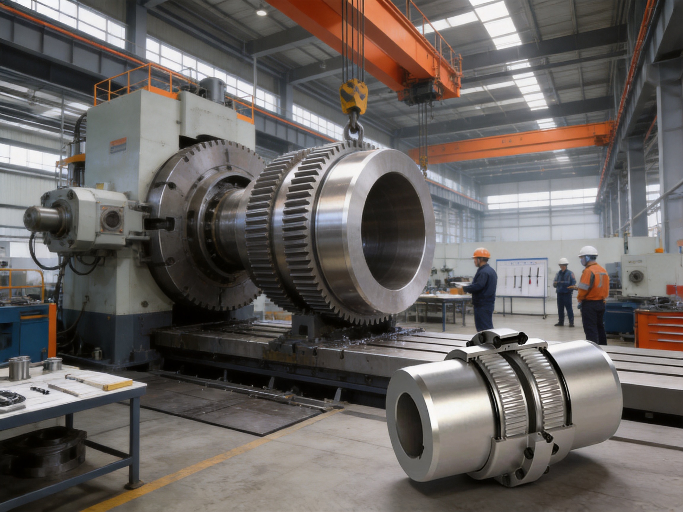
The heavy workshop supports the manufacture and handling of large coupling components. Large gear sleeves and hubs require adequate lifting capacity, machining space, inspection access, and safe material flow. These capabilities are particularly important for GB19 through GB25 models, whose dimensions and masses are far greater than those of compact couplings.
The precision workshop supports accurate machining and inspection of parts requiring close dimensional control. Separating heavy manufacturing areas from precision production areas can help organize workflow and protect accuracy-sensitive operations from unnecessary interference.
The warehouse supports material storage, component control, spare-part management, finished-product handling, and packaging. A structured warehouse process reduces the risk of mixed components and helps maintain product identification during manufacturing and delivery.
The company has a professional and technically experienced team focused on coupling design, production, application support, and service. Its capabilities include standard product supply, custom engineering, non-standard design, technical consultation, pre-sale selection assistance, and after-sales support.
Its product portfolio includes toothed couplings, elastic sleeve pin couplings, elastic pin couplings, gear couplings with elastic pins, universal couplings, tire couplings, jaw couplings, star couplings, diaphragm couplings, drum couplings, grid couplings, Oldham couplings, flange couplings, clamp-shell couplings, roller chain couplings, safety couplings, and other transmission products.
This broad product knowledge benefits customers selecting a coupling because the correct solution is not always the first product considered. A manufacturer familiar with several coupling technologies can compare gear, elastic, diaphragm, grid, tire, chain, rigid, and safety coupling options according to the actual application rather than recommending a single design for every machine.
8. Industrial Applications
8.1 Steel Rolling Mills
Rolling mill equipment transmits high torque under conditions that may include impact, frequent acceleration, reversing operation, thermal exposure, and contamination. Gear couplings are widely used in this type of machinery because they provide a strong mechanical connection while allowing controlled shaft movement.
The GB series can be considered for drive lines connecting motors, gearboxes, rolls, and auxiliary equipment. Model selection must consider the peak rolling torque, speed, shaft diameter, reversal frequency, roll changes, space limitations, and maintenance access.
8.2 Mining Machinery
Mining equipment often operates in dusty, humid, and mechanically aggressive environments. Crushers, conveyors, hoists, feeders, and large pumps may experience fluctuating loads and difficult maintenance conditions.
The enclosed gear structure and grease lubrication of the GB coupling can provide a protected torque-transmission interface. Correct sealing, regular inspection, and contamination control are essential, especially in dusty locations where abrasive particles can accelerate tooth wear.
8.3 Cranes and Lifting Equipment
Cranes and lifting mechanisms undergo repeated starting, stopping, braking, reversing, and load changes. These operating cycles create demanding torque conditions for motors, gearboxes, drums, and couplings.
The GB coupling can provide a robust connection for hoisting and traveling mechanisms when its nominal torque, peak torque, speed, bore, and braking conditions are correctly evaluated. Safety factors and brake torque must be included in the selection process.
8.4 Conveyor Systems
Large conveyors may have long centers, high starting resistance, and considerable inertia. A coupling installed between the motor and gearbox or between gearbox stages must withstand start-up loads and occasional material accumulation.
For these applications, the coupling should be selected using the actual drive torque and service factor. Alignment checks are important because conveyor structures can settle or deflect during operation.
8.5 Pumps and Compressors
Large industrial pumps and compressors require stable power transmission and accurate alignment. Depending on the speed and torsional characteristics of the system, a gear coupling may be selected for its torque capacity and ability to accommodate angular movement.
High-speed applications require special consideration of balance, lubrication, guard design, and vibration monitoring. The coupling must be matched to the driver, driven equipment, shaft stiffness, and operating speed range.
8.6 Paper Machinery
Paper equipment often includes multiple rolls, dryers, winders, pumps, and auxiliary drives. Some sections require high speed and smooth rotation, while others demand high torque and resistance to load variation.
The GB range provides model options for different drive sizes. Environmental factors such as moisture, temperature, washdown practices, and available maintenance time should be considered when specifying seals, grease, and protective finishes.
8.7 Port and Material-Handling Equipment
Port machinery, ship loaders, unloaders, stackers, reclaimers, and heavy conveyors operate outdoors and are exposed to wind, humidity, salt-laden air, dust, and variable loads. A corrosion-resistant surface treatment and properly maintained seals can help improve service performance in these conditions.
The coupling should be installed with suitable guarding and should be included in the equipment’s preventive-maintenance plan. Large models may require dedicated lifting and access provisions for inspection or replacement.
9. Environmental Adaptability and Corrosion Protection
Industrial couplings may operate in environments that include water spray, humidity, dust, oil mist, corrosive gases, temperature variation, and outdoor exposure. The GB product is designed with environmental adaptability in mind and can be supplied with an anti-corrosion surface coating appropriate to the operating environment and customer requirements.
Surface coating protects exposed surfaces, but it does not replace correct sealing or maintenance. The gear cavity must remain adequately sealed so that water and abrasive contaminants do not enter the grease. Damaged coating should be repaired, and damaged seals should be replaced before contamination causes tooth or bearing damage elsewhere in the transmission.
For corrosive environments, customers should provide information about salt spray, chemical vapors, cleaning agents, temperature, and humidity. The manufacturer can then evaluate the appropriate material and surface-treatment requirements. Special environments may require customized seals, coatings, stainless components, or other engineering measures.
10. Lubrication and Maintenance
Lubrication is one of the most important factors affecting gear coupling life. The grease forms a protective film between the gear teeth, reduces friction, limits wear, and helps protect surfaces from corrosion. The required grease quantity varies considerably by model, from approximately 51 mL for GB1 to approximately 43,000 mL for GB25.
The specified grease should be compatible with the operating speed, temperature, load, sealing materials, and environmental conditions. Mixing incompatible greases can reduce performance, so the selected lubricant should be confirmed before replenishment or replacement.
Maintenance personnel should inspect the coupling for grease leakage, damaged seals, unusual noise, elevated temperature, vibration, loose fasteners, corrosion, and evidence of tooth wear. Changes in vibration or temperature may indicate misalignment, insufficient lubrication, contamination, overload, or damage in the coupling or connected equipment.
Maintenance intervals should be established according to operating hours, speed, load, environment, and manufacturer recommendations. Severe-duty equipment may require more frequent inspection than lightly loaded machinery. A documented maintenance program is especially important for large couplings installed in inaccessible areas.
Before servicing, the equipment must be isolated, locked out, and verified to be in a safe condition. Guards should be removed only by authorized personnel, and the coupling should not be inspected while rotating. Large couplings may require lifting devices and temporary supports during disassembly.
11. Installation Recommendations
Correct installation is essential to obtain the intended performance of the GB coupling. Before installation, technicians should verify the model, bore dimensions, shaft-hole length, keyway arrangement, rotation direction where relevant, sealing components, fasteners, grease, and included accessories.
Shafts should be checked for cleanliness, burrs, damage, corrosion, and dimensional conformity. The coupling should not be forced onto a shaft by impact unless a controlled method approved for the design is used. Excessive force can damage the hub, shaft, key, or gear teeth.
The shafts should be aligned according to the applicable installation requirements. Angular and parallel alignment should be measured using suitable instruments. The coupling’s flexibility is intended to accommodate operating movement, not to correct major misalignment caused by poor foundation or incorrect installation.
After assembly, the technician should confirm that the sleeve can move as intended, the seals are correctly positioned, the fasteners are tightened to the specified values, and the gear cavity contains the correct amount of grease. Protective guards must be installed before commissioning.
Initial commissioning should include a controlled low-risk run when possible. Personnel should monitor noise, vibration, temperature, grease leakage, and the behavior of connected equipment. After the first operating period, the coupling and fasteners should be inspected again according to the maintenance plan.
12. Coupling Selection Procedure
Selection should begin with the actual operating data rather than only the motor nameplate rating. The following information is normally required:
1. Driving power and nominal operating torque.
2. Maximum continuous torque and peak or shock torque.
3. Motor speed, driven speed, start-up speed, and braking speed.
4. Shaft diameters, shaft-hole lengths, keyways, splines, and shaft extensions.
5. Angular and parallel misalignment expected during operation.
6. Operating temperature, humidity, dust, chemicals, and outdoor exposure.
7. Starting frequency, reversing frequency, braking cycles, and daily operating hours.
8. Available installation space, outside diameter restrictions, and maintenance access.
9. Dynamic balance requirements and vibration limitations.
10. Applicable standards, inspection requirements, coating requirements, and documentation.
The nominal torque of the selected coupling should exceed the calculated application torque after the appropriate service factor has been applied. The selected speed rating should exceed the actual maximum operating speed. The shaft-hole range and length must be compatible with the shafts, and the outside dimensions must fit within the machine guard.
For special applications, the manufacturer should review the complete duty cycle. This is particularly important for large reversing drives, high-inertia systems, vertical equipment, frequent-impact machinery, and installations in which the coupling must operate close to its maximum speed or torque.
13. Customization and Non-Standard Design
Standard GB models cover a wide range of common industrial requirements, but some machines require special dimensions or operating features. The manufacturer provides customized coupling design and production for non-standard applications.
Customization may involve special bore sizes, non-standard shaft-hole lengths, modified keyways, alternative flange dimensions, different connection details, special seals, corrosion-resistant coatings, modified grease arrangements, or adaptations to existing equipment.
Custom design begins with technical clarification. Drawings, shaft layouts, torque and speed data, installation photographs, duty-cycle information, environmental conditions, and maintenance requirements help engineers develop a suitable proposal. For complex applications, the customer and manufacturer can review the complete power train to avoid a mismatch between the coupling and the connected shafts or gearboxes.
A customized design should be reviewed for strength, stiffness, fatigue, manufacturability, balance, assembly, lubrication, and inspection. Any deviation from the standard configuration should be clearly documented so that future maintenance personnel understand the exact product installed.
14. Reliability, Service Life, and Total Cost
A coupling’s economic value is determined by more than its initial purchase price. Downtime, maintenance labor, replacement parts, emergency repairs, lost production, and damage to connected equipment can all exceed the original component cost.
The GB drum gear coupling supports lower lifecycle risk through robust construction, a wide model range, replaceable service components, established lubrication practices, and application support. Its metallic gear transmission avoids some of the aging mechanisms associated with elastomeric elements, while the enclosed housing helps protect the tooth engagement from external contamination.
Long service life still depends on correct selection and maintenance. Overload, misalignment, insufficient grease, damaged seals, excessive speed, poor balance, and improper installation can shorten the life of any coupling. The best results are achieved when design, production, installation, lubrication, inspection, and operating practices are treated as one complete reliability system.
The manufacturer’s ability to provide both standard and customized couplings can also reduce replacement complexity. Instead of adapting an unsuitable product to an existing machine, customers can request a coupling designed around the actual shaft arrangement and operating conditions. This may reduce modification work and improve the probability of a successful installation.
15. Why Work with an Experienced Coupling Manufacturer?
Coupling selection often appears simple because the component is located between two shafts. In practice, it requires an understanding of torque, speed, misalignment, shaft strength, vibration, lubrication, environment, installation, and maintenance. An experienced manufacturer can help identify risks that may not be obvious from a basic equipment description.
A specialist manufacturer offers several advantages. First, it has knowledge of multiple coupling types and can recommend a product based on the application rather than a limited product catalog. Second, it can support custom engineering when standard dimensions do not fit. Third, it has the production resources needed to manufacture both small precision components and very large heavy-duty parts. Fourth, it can provide technical documents, inspection support, and after-sales assistance.
Zhongye Heavy Industry Technology combines coupling research and development, manufacturing, sales, and service. Its product experience covers metallurgical equipment, mining machinery, water equipment, lifting equipment, paper machinery, port machinery, and other industrial fields. The company also identifies ISO 9001-related quality management and international product compliance as part of its quality system.
Its manufacturing resources include heavy and precision workshops, inspection facilities, warehousing, experienced technical personnel, and custom-design capability. These strengths are relevant to the GB drum gear coupling because the series spans a very wide range of dimensions and masses, from a 3 kg compact model to a model weighing more than 22 tons.
16. Practical Advantages Summary
The GB drum gear coupling offers a combination of high torque capacity, metallic gear transmission, angular misalignment accommodation, broad shaft compatibility, and suitability for severe industrial environments.
Compared with rigid couplings, it provides greater flexibility for operating alignment changes. Compared with many elastic couplings, it offers stronger resistance to high torque, high temperature, chemical exposure, and heavy impact. Compared with smaller general-purpose coupling designs, it provides a much wider range of large-bore and ultra-high-torque models.
The drum-shaped tooth profile improves the distribution of contact across the gear teeth. Precision machining supports dimensional consistency and smooth engagement. Grease lubrication protects the tooth surfaces, while sealing and surface treatment improve environmental adaptability.
The 25-model range makes it possible to select a coupling according to actual torque, speed, shaft diameter, installation dimensions, and mass requirements. For applications outside the standard catalog, the manufacturer can undertake non-standard design and production.
17. Q&A
Q1: What type of coupling is the GB product?
The GB product is a flexible coupling with non-elastic elements. It transmits torque through the engagement of internal and external metallic gear teeth and uses a drum-shaped tooth profile to accommodate controlled angular misalignment.
Q2: What standard does the product follow?
The product is identified according to Q/YG11001X-2018. Customers should confirm the required technical standard, inspection requirements, and documentation for each specific project.
Q3: What is the torque range of the GB series?
The standard series covers nominal torques from 0.63 kN·m for GB1 to 5,600 kN·m for GB25.
Q4: What is the maximum allowable speed?
The highest listed allowable speed is 6,500 r/min for GB1. Allowable speed decreases as model size and rotating mass increase. The exact speed rating must be checked for the selected model and configuration.
Q5: What shaft diameters can the coupling accommodate?
The listed shaft-hole diameter range extends from 16 mm to 1,040 mm. The actual bore should be selected according to shaft size, keyway or spline requirements, shaft extension, transmitted torque, and hub engagement length.
Q6: Can the coupling compensate for shaft misalignment?
Yes. Its crowned drum gear teeth are designed to accommodate controlled angular misalignment. However, the coupling should not be used to compensate for severe alignment errors. Accurate installation remains essential.
Q7: Is the GB coupling suitable for shock loads?
It is designed for medium, heavy, and severe industrial loads, including applications with impact and fluctuating torque. The selected model must be checked against peak torque, shock frequency, reversing conditions, and braking loads.
Q8: Does the coupling require lubrication?
Yes. The gear teeth require suitable grease to reduce friction, wear, and corrosion. Grease quantity varies by model, and maintenance intervals should be established according to speed, load, environment, and operating hours.
Q9: Can the product be used outdoors?
It can be used in outdoor applications when the coupling is correctly sealed, lubricated, guarded, and protected against the site environment. Anti-corrosion surface treatment and special sealing arrangements may be considered for humid or corrosive locations.
Q10: Is the GB series suitable for rolling mills?
Yes. Its high torque capacity, metallic gear transmission, resistance to impact, and ability to accommodate controlled shaft movement make it suitable for many rolling mill drive applications. Detailed selection must consider rolling torque, speed, reversing, shaft dimensions, and installation space.
Q11: Can the manufacturer provide customized couplings?
Yes. Customization and non-standard coupling design are available. Possible modifications include bore dimensions, shaft-hole lengths, keyways, connection details, seals, coatings, and other application-specific features.
Q12: What information should be supplied for a quotation?
Useful information includes power, torque, speed, peak load, shaft diameters, shaft-hole lengths, keyways, misalignment, environmental conditions, operating temperature, duty cycle, available space, installation orientation, and required standards or inspection documents.
Q13: How should large GB couplings be installed?
Large couplings should be installed by trained personnel using appropriate lifting equipment and supports. The shafts must be aligned, the components checked for damage, the seals correctly fitted, the fasteners tightened as specified, and the coupling filled with the correct grease before commissioning.
Q14: What are the main causes of premature coupling failure?
Common causes include incorrect model selection, overload, excessive misalignment, insufficient or incompatible grease, seal failure, contamination, excessive speed, poor balance, loose fasteners, improper bore fit, and inadequate maintenance.
Q15: Does a gear coupling provide torsional vibration damping?
A gear coupling provides mechanical flexibility and misalignment compensation but does not provide the same torsional damping as an elastomeric or other elastic coupling. If vibration isolation is a primary system requirement, the complete transmission should be reviewed before selection.
18. Conclusion
The GB drum gear coupling is a high-capacity industrial transmission solution for equipment that demands strength, durability, and controlled flexibility. Its drum-shaped gear geometry enables reliable torque transfer while accommodating angular shaft movement. The series covers 25 model sizes, allowing applications ranging from compact high-speed machinery to extremely large low-speed heavy-duty systems.
Its advantages include nominal torque capacity up to 5,600 kN·m, bore diameters up to 1,040 mm, high allowable speed in smaller models, resistance to impact, metallic construction, wide industrial applicability, and compatibility with customized engineering requirements.
The performance of the product is supported by the manufacturer’s integrated capabilities in research and development, precision machining, heavy-component manufacturing, inspection, quality management, warehouse control, application engineering, and after-sales support. The combination of standard product breadth and non-standard design capability makes the coupling suitable for both new equipment and replacement projects.
For the best result, users should select the coupling according to actual torque, speed, shaft dimensions, misalignment, environment, duty cycle, and maintenance conditions. When correctly specified, installed, lubricated, and inspected, the GB drum gear coupling can provide a dependable connection for metallurgical, mining, lifting, conveying, fluid, paper, port, and general industrial equipment.
References
1. Q/YG11001X-2018, Technical Standard for GB-Type Drum Gear Couplings.
2. GB Drum Gear Coupling Basic Parameters and Main Dimensions, Manufacturer’s Technical Data.
3. Industrial Gear Coupling Design and Selection Principles, Mechanical Power Transmission Engineering Reference.
4. Industrial Coupling Installation, Alignment, Lubrication, and Maintenance Practices.
5. ISO 9001 Quality Management System Principles for Manufacturing Organizations.
6. General Mechanical Transmission Engineering Guidance for Torque, Speed, Shaft Fit, and Coupling Selection.
Product: GB Drum gear coupling(Q/YG11001X-2018)
- Quick Links
- About
- Products
- Our Service
- News & Events
- Contact
- Products Series
- Flexible Couplings with Non-Elastic Elements
- Flexible Couplings with Metal Elastic Elements
- Flexible Couplings with Non-Metallic Elastic Elements
- Safety Coupling
- Rigid Coupling
- Contact Us
- Tel : +86 511 8572 3800 +86 511 8572 3900
- Mobile : +86 15106109009
- Email : sales@couplingzy.com
- Add:No.1 Zhongye Yingbin Avenue, Gaozi Street, Dantu Economic Development Zone, Zhenjiang City, Jiangsu Province, China.


