:+86 15106109009
:sales@couplingzy.com


 English
 русский
 Español
 عربى
 Português
 Deutsch
 Türk
 Indonesia


QGC Involute Spline Spherical Roller Coupling for Heavy-Duty Transmission
Content
- 1 1. Operating Challenges in Heavy-Duty Shaft Connections
- 2 2. Product Construction and Operating Principle
- 3 3. Main Performance Advantages
- 4 4. Comparison with Traditional Coupling Solutions
- 5 5. Product Range and Technical Parameters
- 6 6. Applications in Industrial Equipment
- 7 7. Advanced Manufacturing Capabilities
- 8 8. Customization and Non-Standard Engineering
- 9 9. Installation and Maintenance Considerations
- 10 10. Selection Method for Engineers
- 11 11. Why Choose This Coupling for Heavy Equipment?
- 12 12. Frequently Asked Questions
- 12.1 What is a QGC involute spline spherical roller coupling?
- 12.2 What industries use this coupling?
- 12.3 What is the torque range of the QGC series?
- 12.4 How much angular displacement can it compensate?
- 12.5 What is the permissible radial force?
- 12.6 How does it compare with a traditional gear coupling?
- 12.7 Can the coupling be customized?
- 12.8 Does the coupling require lubrication?
- 12.9 What does the wear indicator do?
- 12.10 Are the listed mass and moment of inertia exact?
- 12.11 What information is required for model selection?
- 12.12 What manufacturing support is available?
- 13 13. Conclusion
- 14 References
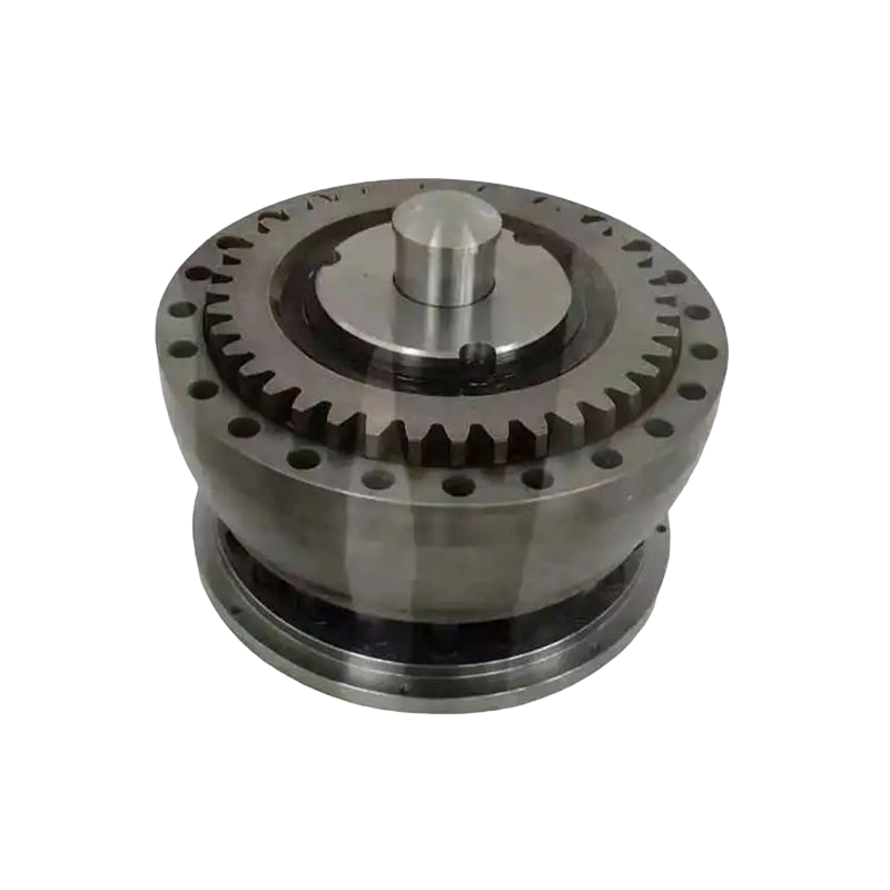
- 15 Product: QGC type involute spline coupling spherical roller coupling(Q/YJ16029X-2018)
Heavy-duty machinery demands a coupling that can transmit high torque, tolerate impact loads, accommodate installation errors, and remain serviceable under difficult operating conditions. Cranes, metallurgical production lines, mining equipment, port machinery, and large lifting systems often operate with frequent starts and stops, fluctuating loads, vibration, and structural deformation. In these applications, a conventional rigid connection can transfer excessive bending moments to connected shafts, while a conventional flexible coupling may not provide sufficient load capacity or durability.
The QGC type involute spline spherical roller coupling, manufactured in accordance with the Q/YJ16029X-2018 standard, is designed to address these demanding requirements. It combines an involute spline transmission system with spherical rollers that support radial loading and permit angular compensation. This construction provides a compact and robust solution for connecting drums, reducers, and other heavy-duty rotating assemblies.
With nominal torque ratings ranging from 5 kN·m to 900 kN·m and permissible radial forces from 16.5 kN to 520 kN across the listed models, the QGC series covers a broad range of industrial transmission requirements. Its spherical contact arrangement allows angular displacement compensation of up to approximately 1.5 degrees, helping reduce alignment-related loads and protecting reducer output shafts from unnecessary fatigue.
Beyond its mechanical performance, the coupling incorporates practical service features, including an anti-detachment structure, sealing system, and wear indicator. These features help improve operational safety, simplify condition monitoring, and shorten inspection and maintenance time. For equipment designers seeking a compact, high-capacity, self-aligning coupling, the QGC series offers a strong alternative to traditional gear couplings and other heavy-duty connection methods.
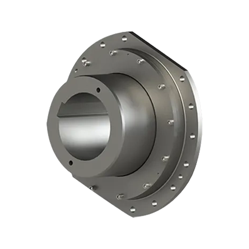
QGC type involute spline coupling spherical roller coupling(Q/YJ16029X-2018)
1. Operating Challenges in Heavy-Duty Shaft Connections
A coupling is not simply a component that joins two shafts. In a large machine, it is part of the complete load-transfer system. It must transmit torque while responding to radial displacement, angular misalignment, axial movement, shock loads, and torsional fluctuations. The actual operating conditions may differ significantly from the ideal alignment established during installation.
In cranes and lifting equipment, for example, a drum and reducer may experience repeated acceleration and deceleration. The load may change rapidly when a suspended object is lifted, stopped, or repositioned. The supporting frame can also deform slightly under load. If the coupling cannot accommodate these movements, the reducer output shaft and drum shaft may be subjected to additional bending forces.
Metallurgical equipment presents another demanding environment. Rolling mills, conveyors, ladle systems, and material-handling equipment operate with high torque and strong impact loads. Heat, dust, vibration, and frequent reversing can accelerate wear in poorly protected coupling components. A suitable coupling must therefore combine high strength with reliable sealing and convenient inspection.
Mining and port machinery may operate continuously in dusty or corrosive environments. Large conveyors, stacker-reclaimers, ship loaders, and hoisting systems require dependable power transmission over long service periods. Unexpected coupling failure can result in production interruption, safety risks, and expensive downtime. For this reason, the coupling must be selected according to the complete operating profile rather than rated torque alone.
Traditional rigid couplings provide accurate torque transmission but offer little tolerance for misalignment. Flexible couplings with elastomeric elements can absorb some displacement and vibration, but the elastic element may be sensitive to temperature, aging, chemical exposure, or severe impact. Traditional gear couplings offer high torque capacity, but their tooth contact and lubrication requirements may not provide the desired combination of radial load capability, angular compensation, compactness, and condition monitoring.
The QGC spherical roller coupling is developed for this type of application. Its operating principle allows torque to be transmitted through involute splines while spherical rollers support the connected assembly and accommodate angular displacement. The result is a coupling that is both structurally strong and mechanically adaptable.
2. Product Construction and Operating Principle
2.1 Involute spline torque transmission
The QGC coupling uses an involute spline connection to transfer torque between the coupling components. Involute splines provide multiple engaging tooth surfaces around the shaft circumference. Instead of concentrating the entire torque load on a single key or a small number of contact points, the spline distributes the load among many teeth.
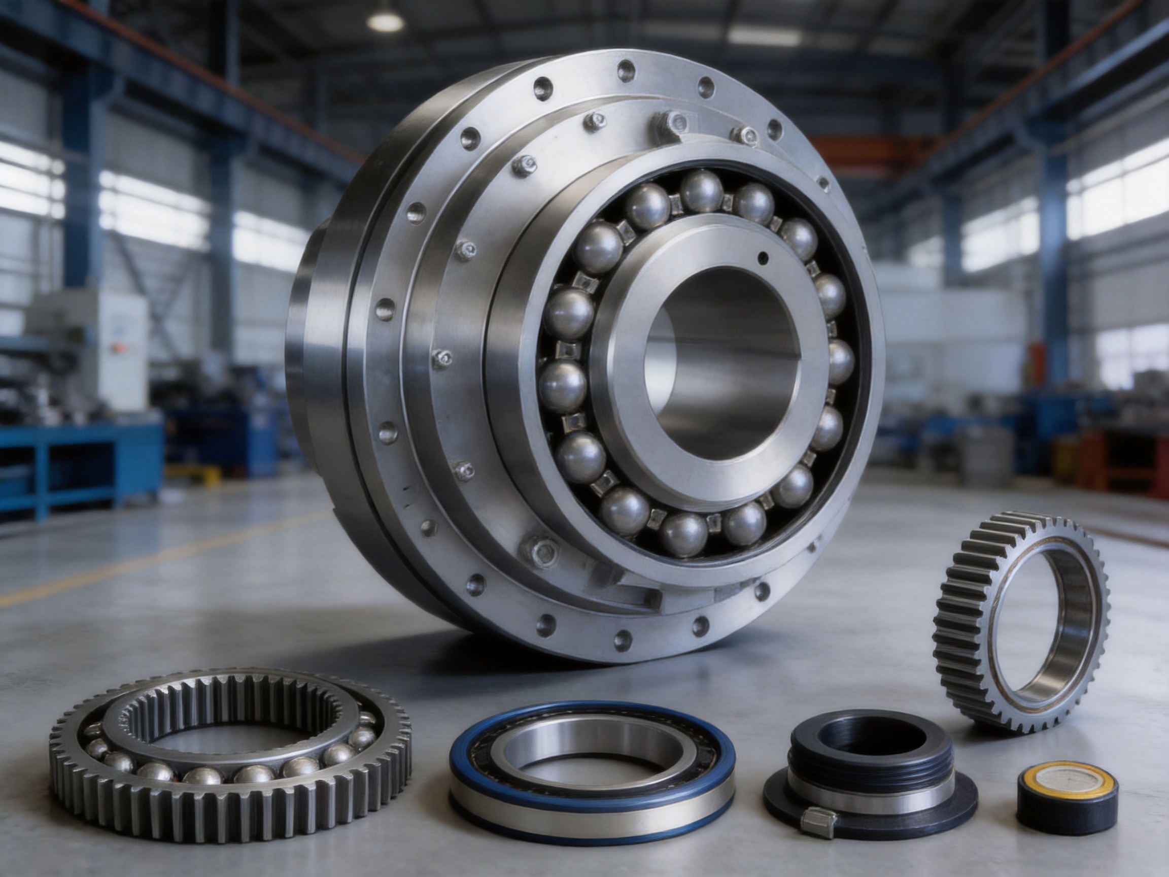
This arrangement supports high torque transmission within a relatively compact radial envelope. It also permits controlled axial assembly and disassembly, which is valuable when the coupling is installed in heavy equipment where maintenance access may be limited. The listed internal spline configurations include designations such as INT16Z×2.5, INT18Z×5m, INT26Z×8m, INT38Z×8m, and INT44Z×8m, depending on the QGC model and shaft connection requirements.
Involute splines are particularly suitable for heavy machinery because the tooth geometry provides progressive engagement and stable load distribution. When properly manufactured, lubricated, and fitted, the spline can transmit large alternating and impact loads while maintaining reliable alignment between the coupling and shaft.
2.2 Spherical roller support
The spherical rollers are the defining feature of the QGC design. The rollers make spherical contact with their corresponding bores or raceway surfaces. This contact geometry allows the coupling to accommodate angular displacement between the connected shafts while continuing to transmit load.
When a reducer shaft and drum shaft are not perfectly coaxial, the spherical rollers can adjust their contact position. This self-aligning behavior helps avoid the edge loading that may occur in a less adaptable connection. It also reduces the additional bending moment transferred to the reducer output shaft.
The angular compensation capability is up to approximately 1.5 degrees under the stated design conditions. The actual permissible displacement in service depends on speed, applied radial force, lubrication, shaft configuration, installation accuracy, and the specific model. The coupling should therefore be selected and installed according to the manufacturer’s technical documentation rather than treating the maximum value as a universal operating target.
2.3 Radial force capacity
Unlike a coupling intended only to transmit torsional power, the QGC series is also designed to handle substantial radial forces. The permissible radial force ranges from 16.5 kN for the smaller QGC1 model to 520 kN for the largest QGC17 model in the supplied specifications.
Radial force may arise from the weight of a drum, gear, pulley, or other rotating assembly. It may also result from chain tension, belt tension, rope loading, external machine reactions, or structural deformation. By supporting this load within the coupling assembly, the QGC design can help reduce the demand placed on adjacent bearings and shafts.
Radial capacity must always be evaluated together with torque, speed, duty cycle, misalignment, and service life. A high permissible radial force does not mean that every machine can apply the maximum radial load at the same time as the maximum torque and angular displacement. Proper application engineering remains essential.
3. Main Performance Advantages
3.1 High load-bearing capacity
The QGC series provides a nominal torque range of approximately 5 kN·m to 900 kN·m across seventeen principal sizes. This broad range enables designers to use the same basic coupling concept in both medium-duty and very large transmission systems.
According to the supplied product information, the load-bearing capacity is approximately 30 percent higher than that of traditional gear couplings under comparable conditions. This advantage can allow a designer to select a more compact coupling for a defined load requirement, or to obtain greater operating margin within an existing installation envelope.
High load capacity is especially valuable in equipment with frequent impact. During crane lifting, steel processing, or mining operations, the actual torque may temporarily exceed the steady-state value. A coupling with adequate reserve capacity is better able to withstand these transient events without permanent deformation or premature fatigue.
3.2 Angular displacement compensation
Installation tolerances, foundation settlement, shaft deflection, bearing clearance, and frame deformation can all create angular misalignment. If the coupling does not accommodate this condition, the connected shafts may experience additional bending stress.
The spherical roller arrangement allows the QGC coupling to act as a self-aligning element. By adapting to angular displacement, it can reduce the additional bending moment applied to the reducer output shaft. Lower bending stress can help reduce shaft fatigue risk, bearing loading, and the probability of damage to adjacent transmission components.
This advantage is particularly important in drum-to-reducer connections. A drum may be supported at a distance from the reducer, and its shaft can deflect under the weight of the drum and the applied working load. The coupling must transmit torque without forcing the reducer shaft to follow every movement of the drum. The QGC design is well suited to this relationship.
3.3 Smooth transmission and reduced noise
The spherical roller and involute spline arrangement promotes stable load transfer. Properly manufactured contact surfaces allow the load to move smoothly through the coupling rather than being concentrated at isolated points. This can help reduce vibration, shock transmission, and operating noise.
Noise and vibration are not only issues of operator comfort. Excessive vibration can accelerate bearing wear, loosen fasteners, damage seals, and create fatigue in supporting structures. A coupling that maintains smooth transmission contributes to the overall reliability of the machine.
3.4 Compact structural arrangement
Space around a reducer output shaft is often limited. A coupling with a large external envelope may interfere with guards, bearings, drums, or support structures. The QGC coupling integrates high-capacity torque transmission and radial support in a relatively compact design.
The dimensions vary by model, with outside diameter D values listed from 250 mm for QGC1 to 950 mm for QGC17. Overall length L ranges from 220 mm to 860 mm in the main table. These dimensions provide equipment designers with clear preliminary data for layout planning while leaving room for final confirmation based on the selected spline configuration and shaft arrangement.
3.5 Improved safety and serviceability
Heavy couplings require careful attention during operation and maintenance. A component that becomes loose or separates unexpectedly can cause extensive equipment damage. The QGC series is equipped with an anti-detachment structure intended to improve retention and operational safety.
The sealing system helps protect internal working surfaces from contamination and helps retain lubricant. Effective sealing is particularly important in mining, metallurgy, and port environments where dust, moisture, scale, and other contaminants may be present.
A wear indicator provides a practical means of monitoring service condition. Instead of relying only on operating noise or unexpected vibration, maintenance personnel can use the indicator as part of a planned inspection routine. Early identification of wear allows replacement or repair to be scheduled during a controlled maintenance window.
4. Comparison with Traditional Coupling Solutions
4.1 Compared with rigid couplings
Rigid couplings are simple and efficient where the connected shafts are accurately aligned and remain stable during operation. However, they cannot compensate effectively for angular or radial displacement. Any movement caused by thermal expansion, foundation settlement, shaft deflection, or structural deformation is transferred directly to the connected equipment.
The QGC coupling provides a more forgiving connection. Its spherical roller system accommodates angular displacement and helps isolate the reducer from some alignment-related bending loads. This makes it more appropriate for large machines in which perfect alignment cannot be maintained under all operating conditions.
4.2 Compared with elastomeric couplings
Elastomeric couplings are useful for vibration damping and moderate misalignment compensation. Their flexible elements can reduce torsional shock and protect machinery from certain dynamic loads. However, elastomers may be affected by temperature, ultraviolet exposure, oil contamination, chemical contact, aging, and repeated overload.
The QGC coupling relies on metallic rolling and spline components rather than a rubber or polymer element for its principal load path. This makes it suitable for heavy-duty applications where high radial force and severe impact exceed the practical range of many elastomeric designs. It also avoids the need to periodically replace a flexible polymer insert solely because of material aging.
4.3 Compared with conventional gear couplings
Gear couplings are widely used for high-torque transmission and can accommodate certain forms of misalignment. However, their performance depends heavily on tooth contact, lubrication, sealing, and the control of backlash and wear. In some installations, gear tooth wear can be difficult to assess without opening the coupling.
The QGC coupling combines spline transmission with spherical roller support. According to the supplied performance description, its load-bearing capacity is approximately 30 percent higher than that of traditional gear couplings. Its angular compensation mechanism also provides a self-aligning action that can reduce additional bending moments on the reducer output shaft.
The wear indicator and accessible service features further support condition-based maintenance. These characteristics can be valuable where unplanned disassembly is difficult or where the cost of production interruption is high.
4.4 Comparison summary
| Evaluation item | Rigid coupling | Elastomeric coupling | Traditional gear coupling | QGC spherical roller coupling |
|---|---|---|---|---|
| Torque capacity for heavy-duty service | High, subject to alignment | Low to medium in many designs | High | High, up to 900 kN·m in the listed range |
| Angular displacement compensation | Very limited | Moderate, depending on element design | Available, depending on tooth geometry | Up to approximately 1.5 degrees under stated conditions |
| Radial force capability | Usually limited by connected shafts and bearings | Application dependent | Application dependent | 16.5 kN to 520 kN across the listed models |
| Impact and frequent start-stop suitability | Good only with excellent alignment | Limited by elastic element fatigue | Good | Designed for demanding impact and start-stop conditions |
| Condition monitoring | Usually basic visual inspection | Element inspection or replacement | Often requires detailed tooth inspection | Wear indicator and service-oriented design |
| Primary service concern | Alignment and shaft stress | Element aging and temperature | Tooth wear, lubrication, and sealing | Lubrication, roller condition, spline wear, and alignment verification |
This comparison is a general engineering overview rather than a substitute for application calculations. A coupling should be selected according to actual torque, speed, radial load, angular displacement, duty cycle, environmental conditions, and required service life.

5. Product Range and Technical Parameters
The QGC product family includes models QGC1 through QGC17. The nominal torque values shown in the supplied data range from 5 kN·m for QGC1 to 900 kN·m for QGC17. Permissible radial force increases from 16.5 kN to 520 kN across the range.
| Model | Nominal torque Tn | Permissible radial force | Typical internal spline designation | D | D1 | D2 | D3 | L | Approximate mass |
|---|---|---|---|---|---|---|---|---|---|
| QGC1 | 5 kN·m | 16.5 kN | INT16Z×2.5 | 250 mm | 220 mm | 160 mm | — | 220 mm | 13.2 kg |
| QGC2 | 7.1 kN·m | 18.5 kN | INT17Z×2.5 | 280 mm | 250 mm | 180 mm | — | 250 mm | 19.8 kg |
| QGC3 | 9 kN·m | 20 kN | INT16Z×2m | 320 mm | 280 mm | 200 mm | — | 280 mm | 22.1 kg |
| QGC4 | 14 kN·m | 25 kN | INT18Z×2m | 340 mm | 300 mm | 220 mm | — | 300 mm | 28.9 kg |
| QGC5 | 18 kN·m | 35 kN | INT22Z×3m | 360 mm | 320 mm | 240 mm | — | 320 mm | 35 kg |
| QGC6 | 22.4 kN·m | 38.5 kN | INT18Z×5m | 380 mm | 340 mm | 260 mm | — | 340 mm | 40 kg |
| QGC7 | 28 kN·m | 42 kN | INT18Z×5m | 400 mm | 360 mm | 280 mm | 150 mm | 360 mm | 51 kg |
| QGC8 | 35.5 kN·m | 49 kN | INT22Z×5m | 420 mm | 380 mm | 310 mm | 168 mm | 380 mm | 59 kg |
| QGC9 | 50 kN·m | 70 kN | INT26Z×5m | 450 mm | 400 mm | 340 mm | 215 mm | 400 mm | 78 kg |
| QGC10 | 100 kN·m | 120 kN | INT34Z×5m | 550 mm | 500 mm | 420 mm | 260 mm | 500 mm | 129 kg |
| QGC11 | 160 kN·m | 140 kN | INT34Z×5m | 580 mm | 530 mm | 450 mm | 285 mm | 530 mm | 151 kg |
| QGC12 | 224 kN·m | 170 kN | INT26Z×8m | 650 mm | 600 mm | 530 mm | 315 mm | 580 mm | 210 kg |
| QGC13 | 355 kN·m | 300 kN | INT26Z×8m | 680 mm | 630 mm | 560 mm | 395 mm | 600 mm | 236 kg |
| QGC14 | 500 kN·m | 340 kN | INT30Z×8m | 710 mm | 660 mm | 600 mm | 395 mm | 640 mm | 301 kg |
| QGC15 | 630 kN·m | 380 kN | INT34Z×8m | 780 mm | 730 mm | 670 mm | 445 mm | 700 mm | 308 kg |
| QGC16 | 710 kN·m | 450 kN | INT38Z×8m | 850 mm | 800 mm | 730 mm | 445 mm | 760 mm | 483 kg |
| QGC17 | 900 kN·m | 520 kN | INT44Z×8m | 950 mm | 900 mm | 840 mm | 585 mm | 860 mm | 797 kg |
The table provides selected principal values for preliminary selection. The complete product data also includes shaft and bore dimensions, spline alternatives, bolt-hole arrangements, installation dimensions, wear scale values, moment of inertia, and other geometry. Some listed values vary according to the internal spline configuration. The final drawing and technical confirmation should therefore be obtained before production or installation.
The supplied data notes that moment of inertia and mass are approximate values calculated using smaller shaft-hole diameters. Actual values can change with the shaft-hole size, spline arrangement, material configuration, and customized design.
6. Applications in Industrial Equipment
6.1 Cranes and lifting machinery
Crane drums and hoisting reducers are among the most suitable applications for the QGC coupling. The connection between a drum and reducer must transmit high torque while accommodating the deflection of the drum shaft and supporting frame. Frequent starts, stops, reversals, and load changes produce severe dynamic conditions.
The coupling’s radial force capacity helps support the drum-related load, while angular compensation reduces the bending effect on the reducer output shaft. The anti-detachment structure provides an additional safety feature in equipment where coupling integrity is critical to operation.
6.2 Metallurgical equipment
Metallurgical machinery commonly operates with high temperatures, heavy loads, vibration, and frequent impact. Examples include rolling mills, coil handling systems, ladle transfer equipment, billet conveyors, and heavy-duty transfer tables.
The QGC coupling is suitable for transmission arrangements where a compact connection must tolerate radial force and alignment changes. Its sealed construction helps protect the internal contact surfaces from scale, dust, and industrial contamination when properly installed and maintained.
6.3 Mining machinery
Mining conveyors, crushers, hoists, bucket-wheel systems, and material-handling machines impose substantial torque and shock loads. They may also operate in remote areas where maintenance access is difficult.
The broad size range enables the coupling to serve both medium-scale and large-scale mining equipment. The wear indicator can support planned inspection, helping maintenance teams identify service needs before coupling damage develops into a larger transmission failure.
6.4 Port and marine terminal equipment
Ship loaders, unloaders, stacker-reclaimers, quay cranes, and heavy conveyors require reliable drive connections. Port machinery may be exposed to wind, humidity, salt-containing air, dust, and repeated loading cycles.
The QGC coupling’s compact arrangement and high load capacity can simplify drive design where space is restricted. Appropriate external protection, lubrication, corrosion control, and inspection remain necessary for long-term service in marine environments.
6.5 Paper, water, and general industrial equipment
The coupling can also be considered for paper machinery, water equipment, large pumps, mixers, and other industrial systems where shafts must remain connected despite moderate structural movement. Each application requires confirmation of operating speed and dynamic behavior, since coupling selection based on torque alone may not adequately address high-speed balancing or torsional resonance.
7. Advanced Manufacturing Capabilities
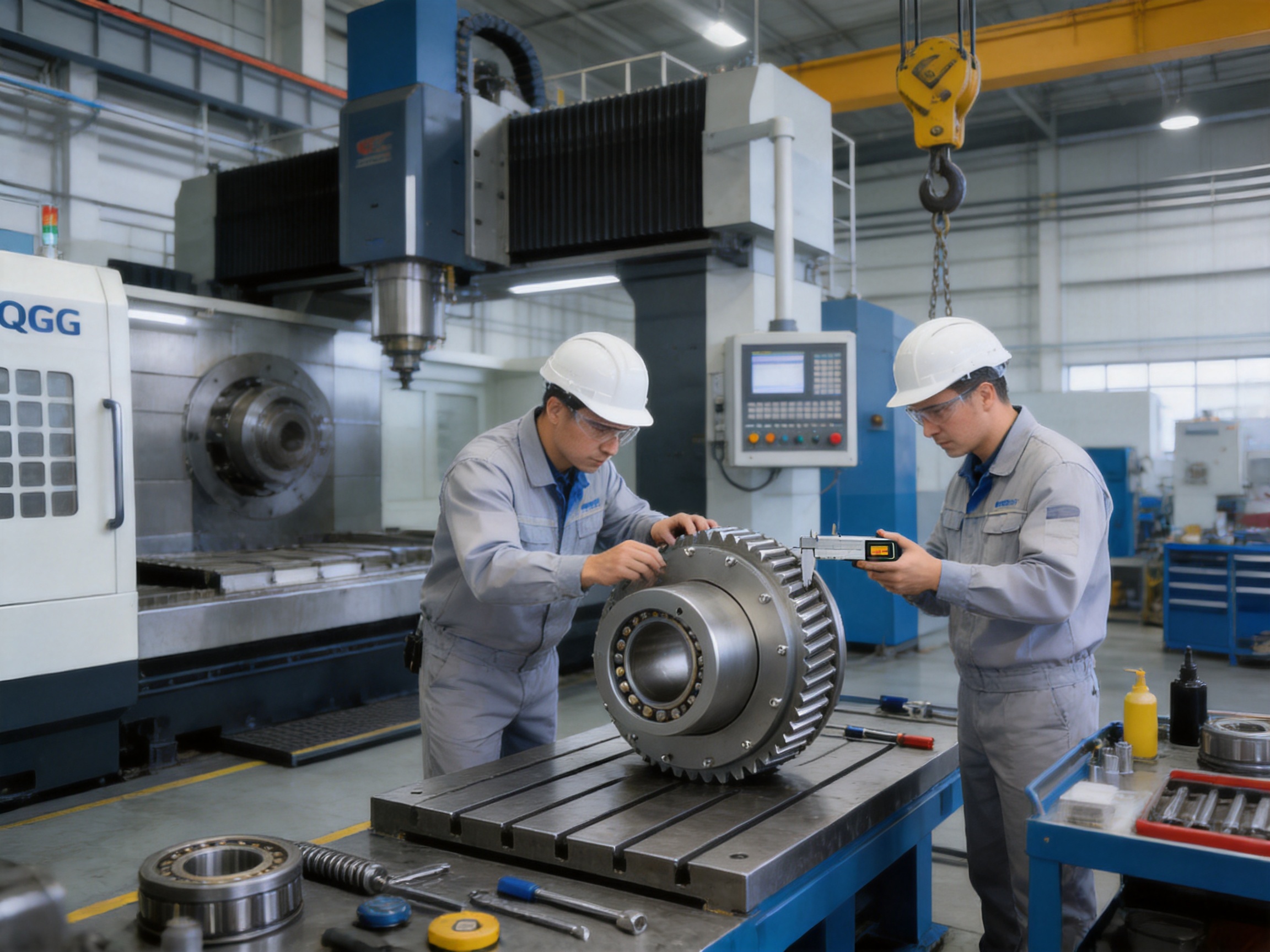
The performance of a spherical roller coupling depends on more than its nominal dimensions. Spline geometry, roller contact, bore accuracy, concentricity, surface finish, heat treatment, sealing quality, and assembly precision all influence service life. For this reason, manufacturing capability is a critical part of product quality.
7.1 Integrated research, development, and production
Zhongye Heavy Industry Technology (Zhenjiang) Co., Ltd. integrates research and development, manufacturing, sales, and technical support. This integrated structure allows product design feedback to move directly between engineering and production teams.
The company manufactures a broad range of coupling products, including toothed couplings, elastic sleeve pin couplings, elastic pin couplings, gear couplings with elastic pins, universal couplings, tire couplings, jaw couplings, star couplings, diaphragm couplings, drum couplings, grid couplings, Oldham couplings, flange couplings, clip-shell couplings, roller chain couplings, safety couplings, and customized non-standard couplings.
This product breadth provides useful engineering experience across different coupling principles. It allows designers to compare rigid, elastomeric, metallic, gear, spline, and customized solutions according to the actual requirements of each machine.
7.2 Workshop capacity
The company’s new workshop covers approximately 16,463.52 square meters. It includes a heavy workshop of approximately 5,500 square meters, a precision workshop of approximately 4,600 square meters, an office building and gymnasium, a dining hall, a warehouse, and supporting roads, green areas, and parking facilities.
The separation between heavy machining and precision manufacturing areas is valuable for large coupling production. Heavy components can be handled with suitable lifting and machining resources, while precision areas can focus on dimensional accuracy, assembly, inspection, and controlled finishing operations.
Large coupling components require appropriate production planning from raw material preparation through final assembly. The manufacturing process must account for material traceability, machining allowance, heat-treatment deformation, spline accuracy, roller fit, seal installation, and final dimensional inspection.
7.3 Precision machining of spline and roller surfaces
Involute spline performance depends on accurate tooth form, pitch, profile, runout, and concentricity. Errors in these areas can cause uneven load distribution, localized wear, noise, and reduced torque capacity. Precision machining and inspection are therefore necessary to ensure that the spline engages smoothly and distributes load correctly.
The spherical roller contact surfaces also require controlled geometry. The roller and bore must work together to accommodate angular displacement without creating damaging edge contact. Surface quality and dimensional consistency influence friction, wear, lubricant retention, and load distribution.
For large couplings, process control is particularly important because component size can magnify the effects of thermal variation, machine deflection, and handling. A capable manufacturer must coordinate machining sequence, measurement, correction, and assembly so that the finished coupling maintains the intended relationship between the spline axis, roller surfaces, and external reference dimensions.
7.4 Quality control and testing
The company identifies strict quality control and advanced testing facilities as important production strengths. Quality control should cover incoming materials, machining operations, heat treatment, spline inspection, dimensional verification, assembly checks, sealing inspection, and final performance confirmation.
Typical inspection activities for a coupling of this type may include dimensional measurement of bores and outside diameters, verification of spline geometry, inspection of roller contact components, concentricity checks, visual examination for surface defects, and confirmation of wear-indicator installation. Depending on the order and application, additional testing or inspection documentation may be arranged.
Quality control is most effective when it is integrated into the entire process rather than performed only at the final stage. Early detection of dimensional deviation reduces rework and helps ensure that all components are compatible before assembly.
7.5 Standards and management systems
The QGC coupling is described as compliant with the Q/YJ16029X-2018 standard. The company also states that its products comply with international standards and certifications such as ISO 9001.
Standards provide a common technical basis for dimensions, performance, inspection, and manufacturing consistency. A quality management system supports document control, process traceability, corrective action, supplier management, and continuous improvement. These practices are particularly important for industrial customers purchasing couplings for critical equipment or repeat production programs.
8. Customization and Non-Standard Engineering
Although the QGC series includes a wide range of standard sizes, some machines require customized dimensions or interfaces. The shaft arrangement may use a special bore, unusual spline, modified flange, different mounting pattern, or non-standard installation length. Space restrictions may also require changes to the outer diameter, hub configuration, or sealing arrangement.
The manufacturer provides non-standard design and manufacturing support. Customization can be developed around the customer’s shaft drawings, reducer model, drum dimensions, operating torque, speed, radial load, misalignment, environmental conditions, and maintenance requirements.
A proper customization process should begin with a complete application specification. Important information includes rated power, operating speed, starting torque, braking torque, peak torque, service factor, duty cycle, shaft diameters, shaft material, allowable overhang, radial force, angular misalignment, axial movement, ambient temperature, contamination, lubrication requirements, and available installation space.
Customers should also specify whether the coupling must be installed or removed without moving the reducer or drum. This requirement can influence the spline length, axial access, fastener arrangement, and the design of the anti-detachment structure.
Customized products should maintain the fundamental design principles of the QGC series: reliable involute spline engagement, controlled spherical roller contact, adequate radial capacity, effective sealing, safe retention, and convenient service access. A custom drawing should be reviewed and approved before manufacturing begins.
9. Installation and Maintenance Considerations
9.1 Installation alignment
The QGC coupling is designed to compensate for angular displacement, but compensation should not be used as a substitute for proper installation. The connected shafts should be positioned as accurately as practical, and the mounting structure should be checked for deformation, looseness, and excessive runout.
Before installation, inspect the shaft ends, spline surfaces, bores, fasteners, rollers, seals, and seating faces. Remove dirt, burrs, scale, and foreign matter. Confirm that the coupling model and spline designation match the shaft and reducer configuration.
The coupling should be installed according to the approved assembly drawing. Forcing the components into position with uncontrolled impact can damage spline teeth, rollers, seals, or precision seating surfaces. Suitable lifting equipment should be used for larger models because the listed mass increases to approximately 797 kg for QGC17.
9.2 Lubrication
Lubrication is essential for the spline and spherical roller contact surfaces. The lubricant type, quantity, replenishment interval, and operating temperature range should follow the manufacturer’s recommendations and the application conditions.
Insufficient lubricant can increase friction, heat, and wear. Excessive or unsuitable lubricant may create leakage, seal deterioration, or contamination problems. Lubrication practices should also consider whether the coupling operates near high temperatures, in dusty environments, or under frequent reversing and impact loads.
9.3 Sealing inspection
The sealing system should be checked during routine maintenance. Inspect for cracks, hardening, displacement, leakage, or contamination. A damaged seal can allow abrasive particles or moisture to enter the internal contact zone, accelerating spline and roller wear.
In harsh environments, inspection frequency may need to be increased. When a seal is replaced, the surrounding surfaces should be cleaned carefully and the correct installation procedure should be followed.
9.4 Wear monitoring
The wear indicator provides a direct maintenance reference. Operators should record the indicator condition during scheduled inspections and compare readings over time. A rapid change may indicate insufficient lubrication, excessive radial load, misalignment, contamination, overload, or another abnormal operating condition.
Wear monitoring should be combined with vibration observation, temperature checks, noise evaluation, and inspection for lubricant leakage. If unusual vibration or temperature is observed, the machine should be examined before continued operation causes secondary damage.
9.5 Planned replacement
Coupling replacement should be planned based on wear condition, operating history, inspection results, and the consequences of failure. For critical equipment, it may be appropriate to keep a replacement coupling or key service components in inventory. The model, internal spline, dimensions, and mass should be recorded clearly to avoid installation errors during an emergency repair.
10. Selection Method for Engineers
The first selection step is to calculate the required design torque. The calculation should consider the motor or engine rating, operating speed, service factor, starting conditions, braking effects, load fluctuation, and any known impact multiplier. The selected nominal torque should exceed the calculated design torque with appropriate margin.
The second step is to evaluate radial force. Determine the force generated by the drum, pulley, gear, chain, belt, rope, or external load. Compare this value with the permissible radial force of the proposed model. If radial force varies during operation, use the maximum credible value rather than the average value.
The third step is to determine angular displacement. Measure or estimate the misalignment caused by shaft deflection, frame deformation, bearing movement, thermal expansion, and installation tolerance. The expected operating angle should remain within the permissible value for the selected model and duty condition.
The fourth step is to verify the shaft and spline interface. Confirm shaft diameter, spline designation, tooth dimensions, insertion length, axial movement, and available assembly access. A coupling with sufficient torque capacity is not suitable if its spline or bore cannot be correctly matched to the shaft.
The fifth step is to check physical dimensions. Compare outside diameter, overall length, mounting-hole arrangement, guard clearance, bearing position, reducer housing, drum support, and maintenance space. The coupling must be safely enclosed and accessible for inspection.
The sixth step is to review environmental and maintenance conditions. Consider temperature, dust, water, corrosive atmosphere, washdown, operating hours, start-stop frequency, lubrication access, and the required inspection interval. These factors may influence the sealing arrangement, material selection, coating, lubricant, and customization requirements.
Finally, request confirmation of the final model and drawing from the manufacturer. The supplied table is useful for preliminary selection, but detailed engineering should be based on the complete technical specification and application review.
11. Why Choose This Coupling for Heavy Equipment?
The primary advantage of the QGC coupling is the combination of functions that are often separated among different coupling types. It transmits high torque through involute splines, supports large radial forces through spherical rollers, accommodates angular displacement through self-aligning contact, and provides service information through a wear indicator.
This multifunctional design can simplify the transmission layout. In some applications, it may reduce the need for additional support arrangements or oversized shaft components. Its compact structure can also help designers fit the drive into restricted spaces without sacrificing the required load capacity.
The coupling is also designed for practical industrial use rather than laboratory conditions alone. Cranes, metallurgy, mining, and port machinery all involve impact, vibration, contamination, and difficult maintenance access. The anti-detachment structure, sealing system, and inspection features address these real operating concerns.
Manufacturing capability further strengthens the product offering. An integrated manufacturer with heavy and precision workshops, product development experience, testing facilities, quality management, and customization support can provide more than a standard catalog component. It can help customers develop a coupling that matches the complete mechanical system.
For customers who require reliable supply, technical support, and repeatable quality, Zhongye Heavy Industry Technology (Zhenjiang) Co., Ltd. provides product design, manufacturing, custom engineering, pre-sale support, and after-sale service. Its experience across multiple coupling categories allows it to recommend a suitable solution rather than treating every application as an identical catalog selection.
12. Frequently Asked Questions
What is a QGC involute spline spherical roller coupling?
It is a heavy-duty coupling that combines involute spline torque transmission with spherical roller support. The spline transmits torque between the connected shafts, while the spherical rollers support radial loads and accommodate angular displacement.
What industries use this coupling?
The primary applications include cranes, metallurgical equipment, mining machinery, port equipment, drum and reducer connections, heavy conveyors, lifting systems, and other industrial drives requiring high torque and radial load capacity.
What is the torque range of the QGC series?
The listed models provide nominal torque ratings from 5 kN·m for QGC1 to 900 kN·m for QGC17. The correct rating must be selected according to actual operating torque, impact, speed, service factor, and duty cycle.
How much angular displacement can it compensate?
The product information states an angular displacement compensation capability of up to approximately 1.5 degrees. The permissible operating value depends on the model, radial load, speed, lubrication, and application conditions.
What is the permissible radial force?
The listed permissible radial force ranges from 16.5 kN for QGC1 to 520 kN for QGC17. The radial force must be evaluated together with torque, angular displacement, speed, and service conditions.
How does it compare with a traditional gear coupling?
According to the supplied product information, the QGC coupling offers approximately 30 percent higher load-bearing capacity than traditional gear couplings under comparable conditions. It also uses spherical roller contact to provide self-aligning behavior and includes a wear indicator for easier condition monitoring.
Can the coupling be customized?
Yes. Custom options may include shaft-hole dimensions, spline configurations, mounting arrangements, overall length, external dimensions, sealing requirements, and other non-standard features. A complete shaft and equipment drawing should be provided for engineering review.
Does the coupling require lubrication?
Yes. The spline and spherical roller contact surfaces require suitable lubrication. The lubricant type, quantity, and maintenance interval should be confirmed with the manufacturer according to operating speed, load, temperature, and environment.
What does the wear indicator do?
The wear indicator helps maintenance personnel assess the service condition of the coupling. It should be checked during planned inspections and interpreted together with vibration, temperature, noise, leakage, and operating history.
Are the listed mass and moment of inertia exact?
No. The supplied technical note states that moment of inertia and mass are approximate values calculated using smaller shaft-hole diameters. Actual values can vary with the shaft-hole size and customized configuration.
What information is required for model selection?
Important information includes rated and peak torque, speed, service factor, start-stop frequency, radial force, angular displacement, shaft dimensions, spline requirements, installation space, environment, temperature, lubrication conditions, and maintenance requirements.
What manufacturing support is available?
The manufacturer provides research and development, production, quality control, technical selection, customized design, manufacturing, pre-sale engineering support, and after-sale service. It also produces a wide range of standard and non-standard coupling products.
13. Conclusion
The QGC type involute spline spherical roller coupling is engineered for heavy-duty machinery in which torque transmission, radial loading, misalignment, safety, and maintainability must be addressed together. Its combination of involute splines and spherical rollers provides a strong and adaptable connection for drums, reducers, and other large rotating assemblies.
With nominal torque ratings up to 900 kN·m, permissible radial forces up to 520 kN, angular compensation of approximately 1.5 degrees, and a broad range of standard sizes, the series can serve many demanding industrial applications. Compared with rigid couplings, it offers greater alignment tolerance. Compared with many elastomeric couplings, it provides a metallic high-load transmission path. Compared with traditional gear couplings, it offers a distinctive spherical roller support concept, higher stated load-bearing capacity, and practical wear monitoring.
The product’s value also depends on manufacturing quality. Accurate spline machining, controlled spherical contact, reliable sealing, careful assembly, advanced inspection, and engineering support are essential to achieving the intended performance. With heavy and precision workshop resources, integrated research and production, quality management, and customization capability, the manufacturer is positioned to support both standard and specialized coupling requirements.
For equipment builders and maintenance teams, the best results come from selecting the coupling as part of the complete transmission system. Torque, radial force, angular displacement, speed, environment, installation space, and maintenance access should all be evaluated before the final model is approved. When correctly specified and maintained, the QGC spherical roller coupling can contribute to safer operation, reduced shaft stress, improved transmission reliability, and longer service life in demanding heavy equipment.
References
1. Q/YJ16029X-2018, Technical Standard for QGC Type Involute Spline Spherical Roller Couplings.
2. Manufacturer-supplied QGC involute spline spherical roller coupling product specifications and dimensional data.
3. Manufacturer-supplied technical note concerning approximate moment of inertia and mass calculations.
4. General engineering principles for involute spline design, rolling contact, coupling selection, lubrication, and industrial shaft alignment.
5. ISO 9001 quality management system principles applicable to industrial component manufacturing and process control.
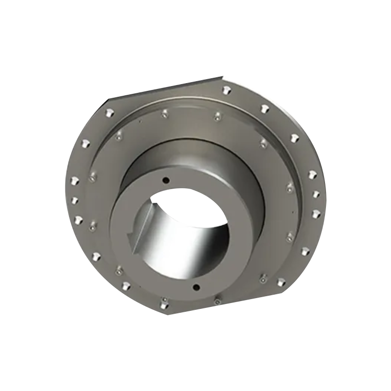
Product: QGC type involute spline coupling spherical roller coupling(Q/YJ16029X-2018)

- Quick Links
- About
- Products
- Our Service
- News & Events
- Contact
- Products Series
- Flexible Couplings with Non-Elastic Elements
- Flexible Couplings with Metal Elastic Elements
- Flexible Couplings with Non-Metallic Elastic Elements
- Safety Coupling
- Rigid Coupling
- Contact Us
- Tel : +86 511 8572 3800 +86 511 8572 3900
- Mobile : +86 15106109009
- Email : sales@couplingzy.com
- Add:No.1 Zhongye Yingbin Avenue, Gaozi Street, Dantu Economic Development Zone, Zhenjiang City, Jiangsu Province, China.


