:+86 15106109009
:sales@couplingzy.com


 English
  русский
  Español
  عربى
عربى  Português
  Deutsch
  Türk
Türk  Indonesia

MC Plum-Shaped Elastic Coupling: Design, Performance, Selection, and Industrial Applications
Content
- 1 1. Construction and Working Principle
- 2 2. Main Performance Advantages
- 3 3. Technical Parameters of the MC Series
- 4 4. How the MC Coupling Compares with Other Coupling Types
- 5 5. Manufacturing Strengths and Production Capabilities
- 6 6. Application Areas
- 7 7. Coupling Selection Procedure
- 8 8. Installation Guidelines
- 9 9. Maintenance and Failure Prevention
- 10 10. Common Failure Modes and Corrective Actions
- 11 11. Why Manufacturer Support Matters
- 12 12. Engineering Value and Total Cost of Ownership
- 13 13. Environmental and Safety Considerations
- 14 14. Recommended Information for an Enquiry
- 15 15. Frequently Asked Questions
- 15.1 Q1: What is an MC plum-shaped elastic coupling?
- 15.2 Q2: Is this coupling also called a jaw coupling or spider coupling?
- 15.3 Q3: What standard does the MC series comply with?
- 15.4 Q4: What is the torque range of the series?
- 15.5 Q5: What is the maximum speed?
- 15.6 Q6: What temperature range is available?
- 15.7 Q7: Does the coupling require lubrication?
- 15.8 Q8: How often should the elastic element be replaced?
- 15.9 Q9: Can the coupling compensate for poor alignment?
- 15.10 Q10: Can the elastic element be replaced without changing the metal hubs?
- 15.11 Q11: Are customized shaft holes available?
- 15.12 Q12: What do the asterisks in the shaft hole table mean?
- 15.13 Q13: Is the MC coupling suitable for lifting equipment?
- 15.14 Q14: What information is needed to select the correct model?
- 15.15 Q15: What are the main advantages over a rigid coupling?
- 15.16 Q16: What are the main advantages over a lubricated gear coupling?
- 16 Conclusion
- 17 References
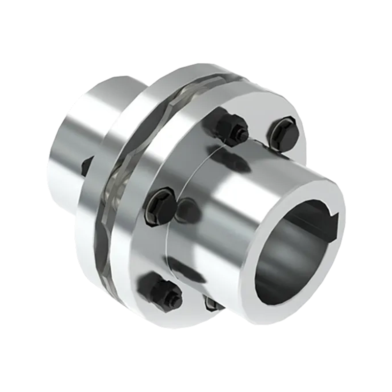
- 18 Product: MC plum shaped elastic coupling(Q/YM 35012X-2018)
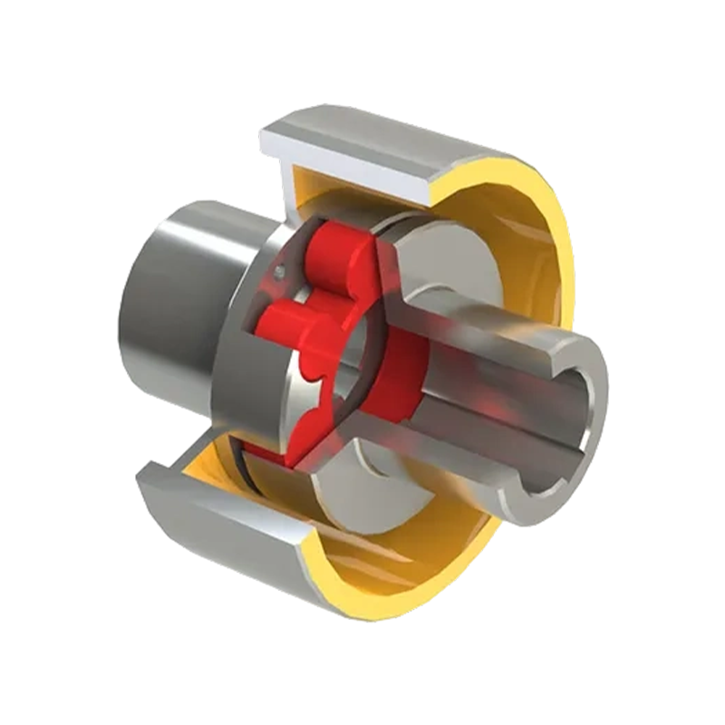
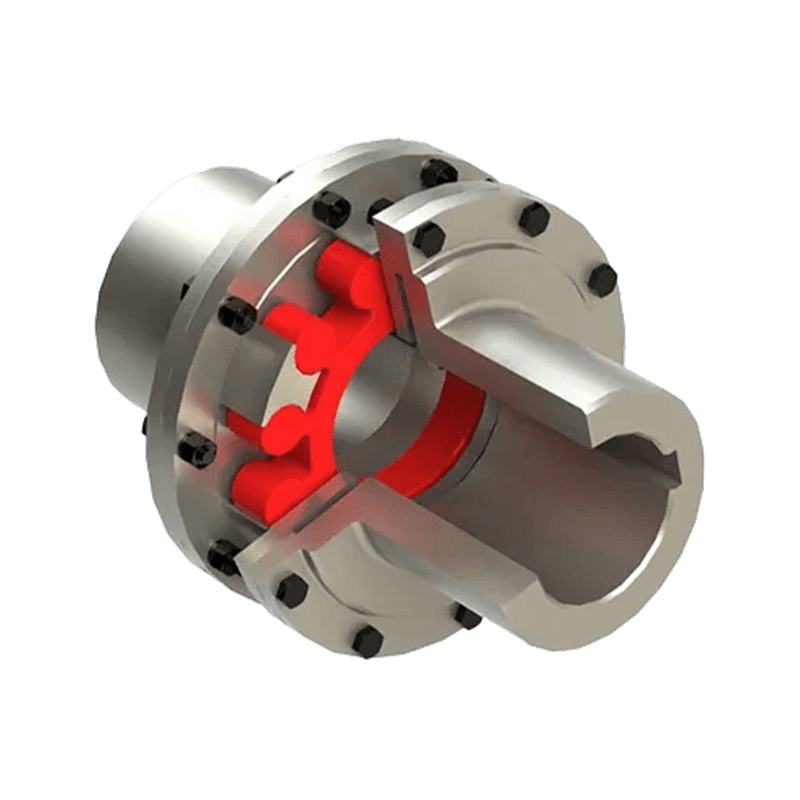
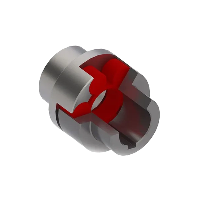
The MC plum-shaped elastic coupling is a high-performance flexible coupling designed for reliable torque transmission, vibration reduction, and convenient maintenance in industrial drive systems. Manufactured in accordance with Q/YM 35012X-2018, this coupling is commonly known in international industrial terminology as a jaw coupling, spider coupling, or plum blossom coupling. Its operating principle is based on two metal half couplings and a non-metallic elastic element positioned between their specially shaped claws.
The coupling provides a practical balance between compact construction, torsional flexibility, shock absorption, speed capability, and ease of installation. Unlike rigid couplings, it can accommodate limited angular, radial, and axial misalignment. Unlike many larger or more complicated flexible couplings, it does not require an extensive collection of bolts, lubrication systems, or complicated maintenance procedures. The elastic element can normally be inspected and replaced without dismantling the connected machinery completely.
The MC series covers a broad nominal torque range from 28 N·m to 14,000 N·m. Its maximum torque range extends from 50 N·m to 25,200 N·m, while allowable speed varies by model from 1,900 r/min to 15,300 r/min. Shaft hole options range from small industrial drive sizes to large bore configurations up to 160 mm. This range enables the same general coupling concept to serve applications from compact equipment to heavy-duty metallurgical, mining, hydraulic, lifting, paper, and port machinery.
More than a simple shaft connector, the MC coupling is a carefully engineered transmission component. The selection of the correct model, elastic element, bore, keyway, and installation arrangement directly affects equipment life, vibration behavior, operating safety, and total maintenance cost. This article explains the construction, working principle, technical characteristics, manufacturing strengths, selection process, applications, maintenance requirements, and frequently asked questions related to the MC plum-shaped elastic coupling.
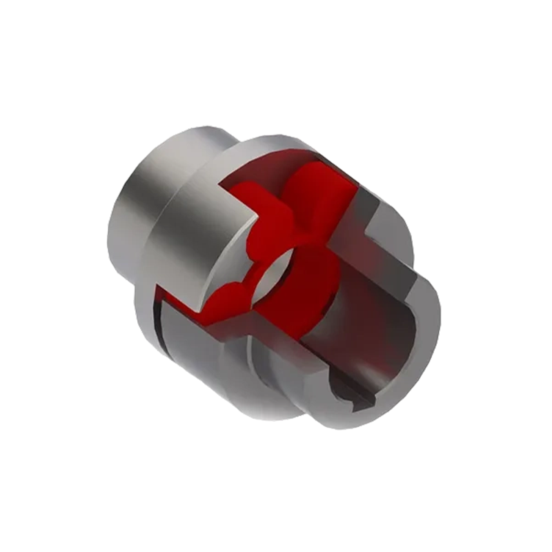
MC plum shaped elastic coupling(Q/YM 35012X-2018)
1. Construction and Working Principle
An MC plum-shaped elastic coupling consists primarily of two half couplings and one elastomeric element. Each half coupling is mounted on one of the two shafts that must be connected. The inner or end face of each half coupling contains multiple convex claws arranged around the circumference. The elastic element is formed with corresponding recesses. During assembly, the elastic element is positioned between the two half couplings, and the claws engage with its recessed sections.
Torque flows from the driving shaft into the first half coupling. The claws then press against the elastic element, which transfers the load to the claws of the second half coupling and ultimately to the driven shaft. The metal components therefore provide the mechanical connection to the shafts, while the non-metallic element provides controlled flexibility between the two halves.
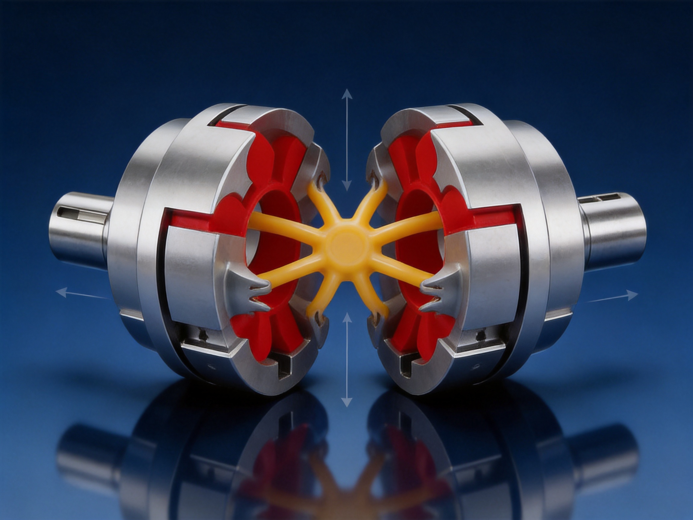
When a motor starts, stops, reverses, or experiences a fluctuating load, the elastic element deforms slightly. This deformation absorbs part of the shock and smooths the transmission of torque. The result is less severe impact between connected machine components. The coupling also helps reduce the transmission of torsional vibration from the motor to the driven equipment and from the driven equipment back to the motor.
The design is intentionally simple. There are no internal gear teeth requiring continuous lubrication, and there is no complex multi-layer diaphragm assembly. The coupling depends on the geometry and material properties of the elastic element rather than on a large number of small mechanical parts. This simplicity improves serviceability and makes routine inspection easier for maintenance personnel.
1.1 Metal Half Couplings
The half couplings provide the load-bearing connection between the shafts and the elastic element. They are manufactured with accurately formed claws, shaft bores, and keyway or other required connection details. The material and manufacturing method are selected to provide adequate strength, dimensional stability, wear resistance, and compatibility with the intended operating conditions.
The geometry of the claws is important because it determines how the load is distributed across the elastic element. Uniform claw dimensions and accurate concentricity help reduce localized stress. Proper surface finish and dimensional control also support smooth assembly and reduce unnecessary wear during operation.
1.2 Non-Metallic Elastic Element
The elastic element is the functional heart of the coupling. It transmits torque while allowing a controlled degree of flexibility. It also absorbs impact and attenuates vibration. The standard MC series uses elastic elements identified from MT1 through MT14, corresponding to the coupling sizes MC1 through MC14.
The elastic element is a wear component. It should therefore be regarded as a replaceable service part rather than an everlasting structural component. Its actual service life depends on transmitted torque, starting frequency, speed, ambient temperature, misalignment, chemical exposure, installation accuracy, and the presence of abnormal shock loads.
The standard operating temperature range stated for this series is approximately -30 °C to +80 °C. Applications outside this range should be reviewed with the manufacturer because elastomer performance can change significantly at low or high temperatures. Temperature affects hardness, flexibility, fatigue resistance, and the ability of the material to absorb energy.
1.3 Compact and Service-Friendly Arrangement
The compact claw-and-spider arrangement allows the coupling to be installed in locations where axial space is limited. Its relatively small number of components also reduces the possibility of assembly errors. Depending on the surrounding equipment and guard arrangement, the elastic element may be accessible for inspection or replacement without moving the connected machines a long distance.
Although the coupling is simple, it must still be installed with proper shaft alignment and adequate guarding. A flexible coupling is not intended to compensate for unlimited misalignment. Excessive angular, radial, or axial displacement can rapidly increase elastic element stress and shorten service life.
2. Main Performance Advantages
The MC plum-shaped elastic coupling combines several characteristics that are valuable in industrial transmission systems. Its advantages do not come from a single feature but from the interaction between its material, geometry, manufacturing accuracy, and broad model range.
2.1 Effective Shock Absorption
Sudden torque changes are common in industrial machinery. Examples include conveyor start-up, crane acceleration, pump loading, rolling equipment engagement, crusher operation, and reversing drives. If these impacts pass directly through a rigid connection, shafts, bearings, gearboxes, and machine frames may experience high transient loads.
The elastic element deforms when torque changes occur, reducing the sharpness of the load transition. This buffering action helps protect the transmission system from impact loads and can contribute to improved operating stability. The coupling does not eliminate the energy of a shock event, but it helps manage the way that energy is transmitted through the drive line.
2.2 Vibration and Noise Reduction
Mechanical drives are affected by motor torque pulsation, shaft eccentricity, gear mesh variation, rotating imbalance, and periodic load changes. A non-metallic elastic element can damp some of these disturbances before they travel from one shaft to the other.
Reducing vibration can provide several practical benefits. Bearings may experience lower dynamic loading, fasteners may be less likely to loosen, and the overall machine may operate with lower noise. The exact reduction depends on system design and installation quality, but the coupling provides a useful layer of torsional compliance within the transmission line.
2.3 Misalignment Compensation
Connected shafts are rarely perfectly aligned under all operating conditions. Thermal expansion, foundation movement, bearing clearance, manufacturing tolerances, and installation limitations can create angular, radial, or axial misalignment. The elastic element allows limited relative movement between the two half couplings.
This capability is a major advantage over rigid couplings, which require substantially better shaft alignment. However, flexibility should not be used to compensate for poor installation. The coupling should be selected and installed so that normal operating misalignment remains within the allowable range specified for the particular design and elastic element.
2.4 Convenient Installation and Replacement
The MC design is recognized for easy assembly and disassembly. The coupling does not depend on an extensive internal lubrication system, and the elastic element is a separate component that can be replaced when wear or aging is detected.
For maintenance departments, this can reduce downtime and simplify spare-parts management. A replacement elastic element can often be kept in inventory at comparatively low cost. The coupling’s simple construction also makes visual inspection practical. Signs of concern include cracks, tearing, excessive deformation, abnormal polishing, hardening, softening, chemical attack, and contact between metal claws.
2.5 Broad Torque and Speed Coverage
The MC product family contains fourteen standard sizes. The smallest model, MC1, has a nominal torque of 28 N·m and an allowable speed of 15,300 r/min. The largest model, MC14, has a nominal torque of 14,000 N·m and an allowable speed of 1,900 r/min.
This broad range allows engineers to select a size that is appropriate for both the torque requirement and the operating speed. High-speed applications generally use smaller, lighter couplings, while heavy-duty applications require larger couplings with greater load capacity. Selecting a coupling according to both conditions is essential because a model that satisfies torque alone may not be suitable for the required speed, bore size, or dynamic balance.
2.6 Adaptability to Various Shaft Diameters
The MC series provides multiple shaft bore options for each model. Depending on size, bore options include diameters from approximately 12 mm through 160 mm. Certain shaft hole diameters identified with an asterisk may be used for Z-type shaft holes, subject to the relevant shaft hole length requirements and confirmation with the manufacturer.
This range supports standard motor shafts, gearbox input shafts, pump shafts, fan shafts, conveyor drive shafts, and other industrial shaft arrangements. Bore and keyway details should always be confirmed before ordering because the available bore is related to the selected coupling size and half-coupling configuration.
3. Technical Parameters of the MC Series
The following table summarizes the basic parameters and principal dimensions of the standard MC plum-shaped elastic coupling range. The data should be used for preliminary selection. Final selection must also consider application factor, starting conditions, load type, shaft arrangement, misalignment, temperature, environment, and installation requirements.
| Type | Nominal Torque Tn (N·m) | Maximum Torque Tmax (N·m) | Allowable Speed (r/min) | Available Shaft Hole Diameters (mm) | L (mm) | L0 (mm) | D (mm) | Elastic Element | Approximate Mass (kg) | Moment of Inertia (kg·m²) |
|---|---|---|---|---|---|---|---|---|---|---|
| MC1 | 28 | 50 | 15,300 | 12, 14, 15, 18, 19, 20, 22, 24, 25 | 35 | 86 | 50 | MT1 | 1.0 | 0.00022 |
| MC2 | 50 | 100 | 12,000 | 16, 18, 19, 20, 22, 24, 25, 28, 30 | 38 | 95 | 60 | MT2 | 1.5 | 0.00044 |
| MC3 | 112 | 200 | 10,900 | 20, 22, 24, 25, 28, 30, 32 | 40 | 103 | 70 | MT3 | 2.5 | 0.00087 |
| MC4 | 160 | 288 | 9,000 | 22, 24, 25, 28, 30, 32, 35, 38, 40 | 45 | 114 | 85 | MT4 | 3.42 | 0.00200 |
| MC5 | 355 | 640 | 7,300 | 25, 28, 30, 32, 35, 38, 40, 42, 45 | 50 | 127 | 105 | MT5 | 5.15 | 0.00490 |
| MC6 | 450 | 810 | 6,100 | 30, 32, 35, 38, 40, 42, 45, 48 | 55 | 143 | 125 | MT6 | 10.1 | 0.01140 |
| MC7 | 710 | 1,280 | 5,300 | 35*, 38*, 40*, 42*, 45, 48, 50, 55 | 60 | 159 | 145 | MT7 | 13.1 | 0.02320 |
| MC8 | 1,250 | 2,250 | 4,500 | 45*, 48*, 50, 55, 56, 60, 63, 65 | 70 | 181 | 168 | MT8 | 21.2 | 0.04680 |
| MC9 | 2,000 | 3,600 | 3,750 | 55*, 56*, 60, 63, 65, 70, 71, 75, 80 | 80 | 208 | 198 | MT9 | 33.0 | 0.10410 |
| MC10 | 3,150 | 5,670 | 3,250 | 60*, 63*, 65*, 70, 71, 75, 80, 85, 90, 95, 100 | 90 | 230 | 228 | MT10 | 45.5 | 0.21050 |
| MC11 | 5,000 | 9,000 | 3,000 | 70, 71*, 75*, 80*, 85*, 90, 95, 100, 110, 120 | 100 | 260 | 258 | MT11 | 75.2 | 0.43380 |
| MC12 | 7,100 | 12,780 | 2,500 | 80*, 85*, 90*, 95*, 100, 110, 120, 125, 130 | 115 | 297 | 298 | MT12 | 99.2 | 0.82000 |
| MC13 | 12,500 | 22,500 | 2,150 | 90*, 95*, 100*, 110*, 120*, 125*, 130, 140, 150 | 125 | 323 | 358 | MT13 | 148.1 | 1.67200 |
| MC14 | 14,000 | 25,200 | 1,900 | 100*, 110*, 120*, 125*, 130*, 140, 150, 160 | 135 | 333 | 400 | MT14 | 197.5 | 2.49900 |
The listed mass and moment of inertia are approximate values calculated using cast steel material assumptions and the largest shaft hole for each model. Actual values may vary according to material, bore size, keyway arrangement, balancing requirements, and customized construction.
Shaft hole diameters marked with an asterisk may be suitable for Z-type shaft holes. If the shaft hole length must comply with the dimensions specified by GB/T 3852, the shaft arrangement should be discussed with the manufacturer before production.
4. How the MC Coupling Compares with Other Coupling Types
Industrial coupling selection is not based on one universal design. Gear couplings, diaphragm couplings, grid couplings, tire couplings, sleeve couplings, rigid couplings, and other designs each have specific strengths. The MC plum-shaped elastic coupling is competitive because it offers a useful combination of performance and simplicity for applications that do not require the extreme misalignment capacity or specialized characteristics of another coupling type.
4.1 Compared with Rigid Couplings
Rigid couplings provide a direct, stiff connection between shafts. They are suitable where shafts are precisely aligned and where no flexibility is required. However, they transmit shock and vibration with little attenuation and can place high loads on bearings when alignment changes.
The MC coupling provides a more forgiving connection. Its elastic element accommodates limited misalignment and softens transient torque. This makes it more suitable for general industrial equipment in which alignment may change during operation or in which the drive experiences starting and stopping loads.
4.2 Compared with Gear Couplings
Gear couplings are widely used for high torque and certain demanding industrial applications. They can provide high capacity in a compact envelope, but their tooth surfaces require lubrication and regular maintenance. Sealing, grease condition, tooth wear, and installation procedures must be carefully managed.
The MC coupling has a simpler maintenance profile because its torque-transmitting flexibility comes from a replaceable elastomer rather than lubricated gear teeth. This can be advantageous in applications where maintenance access is limited or where avoiding lubricant leakage is important. Gear couplings may remain preferable for certain very high torque, high-temperature, or high-misalignment duties, but the MC design is often more economical and convenient for general-purpose machinery.
4.3 Compared with Diaphragm Couplings
Diaphragm couplings are precision components capable of high speed and low backlash. They are often selected for turbines, compressors, generators, and other systems requiring particular torsional or axial characteristics. Their thin metallic membranes, however, require careful alignment and protection from excessive installation errors or external damage.
The MC coupling offers a more straightforward structure and simpler replacement procedure. Its elastomer provides useful damping that is not normally the primary characteristic of a metallic diaphragm coupling. For industrial drives where shock absorption and economical maintenance are more important than extremely precise torsional behavior, the MC design can be a strong alternative.
4.4 Compared with Grid and Tire Couplings
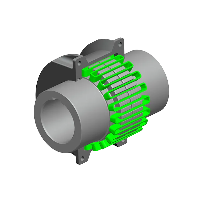
Grid couplings provide high torque capacity and good shock absorption through a spring-like grid element, but they commonly require lubrication and more involved assembly. Tire couplings offer strong flexibility and vibration isolation, although their envelope size and construction may not be ideal for every installation.
The MC coupling occupies a practical middle position. It has a compact radial envelope, a replaceable non-metallic element, and no routine lubrication requirement for the elastic interface. This makes it attractive for pumps, fans, conveyors, small gearboxes, lifting mechanisms, and many other standard drive systems.
4.5 Compared with Other Non-Metallic Elastic Couplings
Within the category of non-metallic elastic couplings, the MC design is distinguished by its claw-and-spider geometry, broad size range, simple construction, and convenient access to the elastic element. It can provide a good balance between flexibility and positive torque transmission without relying on a sleeve that surrounds the entire shaft connection.
Its performance depends strongly on the quality and hardness of the elastic element. A reliable manufacturer must therefore control elastomer formulation, molding accuracy, hardness, dimensional stability, and material traceability. The metal half couplings must also be accurately machined so that the element is loaded evenly.
5. Manufacturing Strengths and Production Capabilities
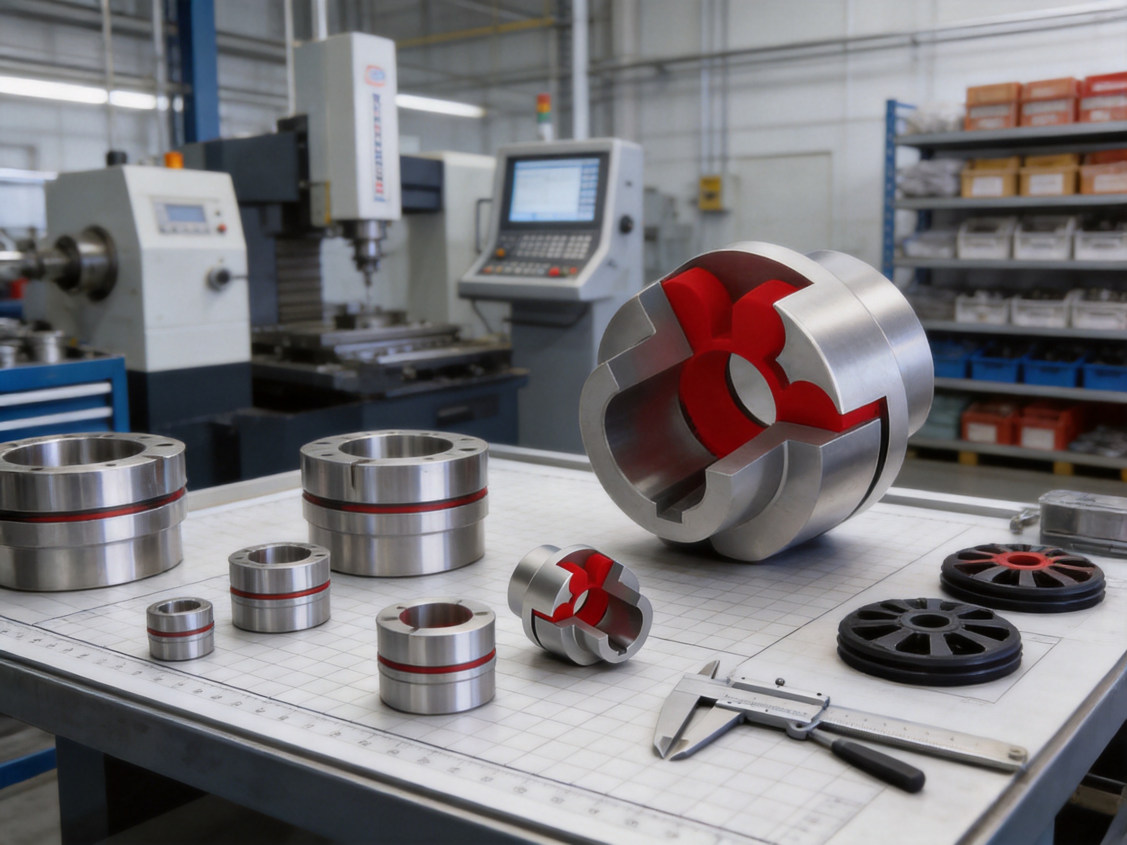
The performance of an elastic coupling is closely connected to the production system behind it. A coupling may have an attractive nominal rating, but inconsistent machining, poor material control, inaccurate bore dimensions, or weak inspection practices can reduce actual service reliability. The manufacturer of the MC series integrates research and development, manufacturing, sales, technical support, and after-sales service to provide a complete coupling supply capability.
The company operates a new workshop with a reported total area of approximately 16,463.52 square meters. The facility includes a heavy workshop of about 5,500 square meters, a precision workshop of about 4,600 square meters, an office building and gymnasium of approximately 2,000 square meters, a dining hall of about 500 square meters, a warehouse of approximately 1,000 square meters, and remaining areas for roads, landscaping, and parking.
5.1 Heavy Manufacturing Capability
The heavy workshop supports the production of large coupling components and other industrial transmission products. Large MC models, including MC11 through MC14, require suitable handling, machining, inspection, and storage capability. The approximate mass of the largest standard model is 197.5 kg when calculated using the stated material and largest bore assumptions.
Heavy manufacturing capability is important because large components must remain dimensionally stable during machining and handling. The production process must control runout, concentricity, face alignment, bore dimensions, and claw geometry. Adequate lifting and handling arrangements also help protect finished surfaces and reduce the risk of accidental damage before shipment.
5.2 Precision Workshop and Dimensional Control
The precision workshop supports the machining and inspection of coupling components requiring controlled tolerances. Critical features include the shaft bore, keyway, end face, external diameter, claw profile, overall length, and relationship between the bore axis and claw geometry.
Dimensional accuracy affects both installation and operating performance. An undersized or oversized bore may prevent correct mounting or create an insecure shaft connection. Excessive runout may increase vibration, especially at high speed. Inaccurate claw geometry can create uneven loading in the elastic element, increasing wear and heat generation.
A professional manufacturing process therefore uses controlled drawings, defined process routes, appropriate machining equipment, inspection instruments, and documented quality records. Each stage should support the next stage rather than relying only on final inspection to discover defects.
5.3 Research and Development
The manufacturer maintains research and development capabilities for standard and customized coupling products. This is valuable because real industrial applications often involve special shaft dimensions, unusual installation spaces, high starting torque, reversing operation, brake integration, corrosive environments, or a need to connect equipment from different manufacturers.
Engineering support can assist with model selection, torque calculation, bore configuration, keyway requirements, spacer arrangements, guard dimensions, and non-standard coupling design. The company also undertakes the design and manufacture of various non-standard couplings, allowing customers to obtain a coordinated solution instead of adapting an unsuitable standard product.
5.4 Product Breadth and Technical Experience
In addition to plum-shaped elastic couplings, the company produces or supports a wide range of coupling categories. These include toothed couplings, elastic sleeve pin couplings, elastic pin couplings, gear couplings with elastic pins, universal couplings, tire couplings, jaw couplings, star couplings, diaphragm couplings, drum couplings, grid couplings, Oldham couplings, flange couplings, clip-shell couplings, roller chain couplings, safety couplings, and customized designs.
This product breadth gives the engineering team experience across different transmission principles. It also enables a more objective selection process. If an MC coupling is not the best choice for a particular temperature, speed, torque, or misalignment condition, another coupling type may be evaluated within the same technical supply system.
5.5 Quality Management and Testing
The company states that its products comply with international standards and certifications such as ISO 9001. A quality management system provides a framework for controlled purchasing, production documentation, inspection, nonconformance management, corrective action, and customer feedback.
For MC couplings, quality control should include verification of raw material or casting quality, machining dimensions, bore and keyway accuracy, surface condition, runout, elastic element characteristics, assembly fit, and marking. For high-speed applications, additional balance and rotational checks may be required according to the equipment specification.
Testing facilities and process inspection are especially important for large and customized couplings. The customer may require inspection reports, material certificates, dimensional records, hardness data, balancing documentation, or other technical files. The ability to support these requirements improves confidence in the product and helps integrate the coupling into a broader equipment quality system.
5.6 Customization and Non-Standard Manufacturing
Standard shaft bores and dimensions meet many industrial requirements, but customized products may be needed when shaft diameters, keyways, axial distances, mounting limitations, or operating conditions fall outside the standard range. Customization may involve a special bore, a modified hub length, a different connection arrangement, a special surface treatment, a customized elastic element, or an entirely different coupling configuration.
Successful customization requires complete application information. The manufacturer should receive shaft diameters, shaft lengths, keyway standards, rated power, operating speed, torque, starting torque, duty cycle, ambient temperature, installation space, misalignment, environmental conditions, and any required certifications. The more complete the data, the more accurately the coupling can be designed and verified.
6. Application Areas
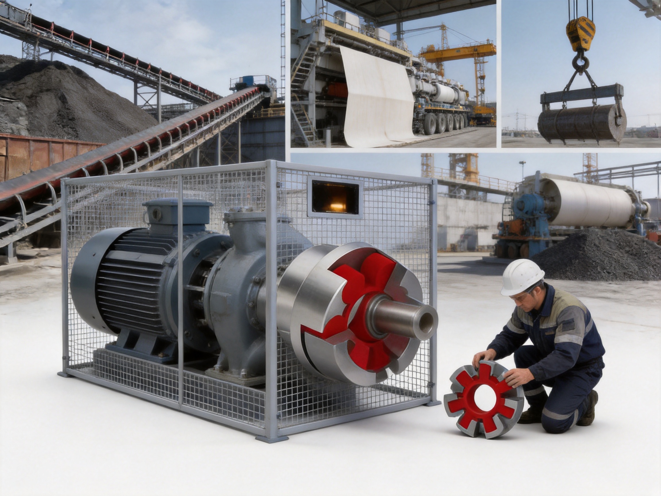
The MC plum-shaped elastic coupling is suitable for a wide variety of industrial drive systems. Its applications are supported by the combination of shock absorption, compact construction, broad torque capacity, speed range, and ease of maintenance.
6.1 Metallurgical Equipment
Metallurgical machinery often operates under heavy loads, frequent starts and stops, elevated temperatures, and severe vibration. Conveying systems, auxiliary drives, pumps, fans, and process machinery may all require flexible shaft connections.
The MC coupling can help reduce the transmission of impact loads and accommodate limited alignment changes caused by large equipment foundations or thermal movement. For hot areas or applications exposed to radiant heat, the stated temperature range must be carefully evaluated, and suitable protection or an alternative coupling material may be required.
6.2 Mining Machinery
Mining equipment commonly encounters fluctuating loads, dust, shock, and difficult maintenance conditions. Crushers, feeders, conveyors, pumps, screens, and auxiliary drives benefit from couplings that are straightforward to inspect and do not require frequent lubrication.
The elastic element provides a buffer against load variation, while the metal claws offer positive torque transmission. Correct guarding is essential in mining environments because dust and debris should not be allowed to interfere with rotating components or contaminate the coupling interface.
6.3 Hydraulic and Water Equipment
Pumps, hydraulic power units, water treatment systems, and other fluid-handling equipment often use electric motors connected to pumps or auxiliary machinery. These drives may experience frequent starts, variable flow conditions, or alignment changes from pipe loads and foundation movement.
The MC coupling can provide a compact connection with useful torsional damping. During installation, care should be taken to ensure that pipe forces are not transferred into the pump shaft and that the motor and pump remain correctly aligned after all piping has been connected.
6.4 Lifting and Transportation Equipment
Cranes, hoists, winches, conveyors, and transport systems may experience repeated acceleration, deceleration, braking, and reversing. These operating cycles can create significant transient torque.
A flexible coupling with an elastomeric element can reduce the severity of these torque changes. However, lifting equipment is safety-critical. The coupling must be selected using the complete duty cycle, including brake torque, emergency stopping conditions, shock factors, and possible load reversals. A standard nominal torque comparison alone is not sufficient.
6.5 Papermaking Machinery
Paper machinery contains numerous rotating shafts, rolls, pumps, fans, and auxiliary systems. Some areas require high speed and low vibration, while others experience moisture, process chemicals, or continuous operation.
The MC series offers several speed and torque options for supporting equipment. The environmental compatibility of the elastic element should be checked where water, steam, oils, cleaning chemicals, or process liquids may contact the coupling. Proper guarding and inspection intervals are also important because paper production frequently operates with limited opportunities for shutdown.
6.6 Port and Material-Handling Equipment
Port machinery operates outdoors and may be exposed to humidity, salt-laden air, wind, dust, and variable loads. Conveyors, stackers, reclaimers, loading equipment, pumps, and drive systems can benefit from a coupling that is easy to maintain and available in a broad range of sizes.
For these installations, corrosion protection of the metal components and environmental suitability of the elastomer should be reviewed. The coupling guard should prevent water accumulation and protect the rotating assembly from external objects while allowing sufficient ventilation and inspection access.
7. Coupling Selection Procedure
Correct selection begins with the actual operating conditions rather than the shaft diameter alone. The following procedure provides a practical engineering framework.
7.1 Determine the Operating Torque
For a motor-driven machine, operating torque can be estimated from power and speed using the relationship:
T = 9550 × P / n
In this expression, T is torque in N·m, P is power in kW, and n is rotational speed in r/min. The calculated running torque should then be adjusted for the application duty, starting characteristics, load fluctuations, reversing, braking, and operating hours.
The selected coupling should not be sized only for average running torque when the machine produces substantial peak or starting loads. The nominal torque rating should be compared with the design torque, and the maximum torque rating should be considered for short-duration overloads or transient events.
7.2 Consider the Service Factor
Different machines impose different levels of stress. A smoothly loaded fan may have a lower service requirement than a crusher, hoist, or reversing conveyor. A suitable application factor should be applied according to the equipment type and duty cycle.
Where the drive starts frequently, reverses often, or experiences impact loading, a larger coupling size or a more suitable elastic element may be required. If the system has high inertia, the acceleration time and starting torque should be included in the evaluation.
7.3 Check Speed
The operating speed must remain below the allowable speed of the selected model. High-speed applications also require attention to balance, mounting accuracy, shaft runout, and guard clearance. The MC1 model has the highest stated allowable speed at 15,300 r/min, while larger models have progressively lower allowable speeds.
It is not advisable to select a large coupling for a high-speed application merely because its torque rating is greater. The coupling must satisfy torque, speed, bore, dimensions, and dynamic requirements simultaneously.
7.4 Confirm Bore and Keyway
The shaft holes of both half couplings must match the actual shaft diameters. The keyway dimensions, key fit, shaft extension, hub length, and axial position must also be checked. A coupling bore should not be enlarged beyond the approved design limits without engineering review.
For shaft holes marked with an asterisk, the suitability for Z-type shaft holes and the required shaft hole length should be confirmed. If the shaft arrangement must follow GB/T 3852, the final configuration should be agreed with the manufacturer before manufacture.
7.5 Check Installation Space
Verify the coupling outside diameter D, overall length L0, and the relevant axial dimensions. There must be enough space for installation, removal, elastic element replacement, and protective guarding. The coupling should not contact nearby structures during operation.
Where the coupling is installed between a motor and gearbox, the distance between shaft ends should be compared with the coupling’s required dimension. If an unusual shaft-end distance exists, a customized arrangement or spacer design may be more appropriate.
7.6 Evaluate the Environment
Temperature, humidity, oil, water, chemicals, dust, ultraviolet radiation, and electrical conditions can influence the service life of the elastic element. The standard temperature range is approximately -30 °C to +80 °C. Applications beyond this range or with aggressive chemicals require additional confirmation.
8. Installation Guidelines
Proper installation is one of the most important factors affecting coupling performance. Even a well-manufactured coupling may fail prematurely if the shafts are misaligned, the bores are damaged, or the fasteners are incorrectly tightened.
8.1 Inspect All Components
Before installation, inspect both half couplings, the elastic element, keys, set screws, bolts, shaft ends, and related hardware. Confirm that the model and bore sizes match the approved order. Remove rust, dirt, burrs, protective coatings in the seating areas, and foreign material from the shaft and bore surfaces.
Do not install an elastic element that shows cracks, cuts, deformation, hardening, softening, or other visible damage. Storage conditions are also important. Elastomeric components should be kept away from direct sunlight, ozone-producing equipment, excessive heat, oils, solvents, and sharp objects.
8.2 Prepare the Shafts
The shaft ends should have suitable surface condition, correct diameter, appropriate keyway dimensions, and sufficient length for the hub. Check for burrs around the keyway and ensure that the key does not project excessively above the shaft surface. An improperly fitted key can create local stress and prevent the hub from seating correctly.
8.3 Mount the Half Couplings
Position each half coupling according to the required shaft-end distance. Do not use excessive impact force to drive a coupling onto a shaft. If heating is used for an interference fit, the temperature must be controlled to avoid damaging the finish, elastomer, or nearby components.
Set screws, clamping screws, keys, or other shaft retention methods must be installed according to the approved design. Fasteners should be tightened using appropriate tools and torque values. The connection must be secure but should not distort the hub.
8.4 Align the Shafts
Measure angular and parallel alignment with suitable instruments. Correct alignment reduces the working deformation of the elastic element and improves service life. Alignment should be checked after the equipment is bolted down and again after connected piping, guards, brakes, or other components have been installed.
Flexible couplings can compensate for limited misalignment, but they should not be used as a substitute for shaft alignment. Excessive misalignment can cause heat, accelerated wear, claw contact, vibration, and premature elastomer failure.
8.5 Install the Elastic Element and Guard
Insert the elastic element between the two half couplings without forcing or cutting it. The claws should engage evenly with the recesses. Confirm that the element is not twisted, folded, trapped, or locally compressed.
After installation, fit a suitable guard around the rotating assembly. The guard should comply with applicable workplace safety requirements and should prevent contact with rotating parts. It should also allow reasonable inspection and ventilation.
9. Maintenance and Failure Prevention
Routine maintenance for the MC coupling is generally straightforward, but it should be systematic. The elastic element is the part most likely to show service-related deterioration, and early detection can prevent secondary damage to the metal half couplings, shafts, bearings, and connected machines.
9.1 Regular Visual Inspection
Inspect the elastic element for cracking, tearing, surface wear, deformation, discoloration, swelling, hardening, and softening. Look for signs that the claws are contacting one another directly. Metal-to-metal contact usually indicates severe element wear, excessive misalignment, overload, incorrect assembly, or an unsuitable element.
9.2 Monitor Vibration and Temperature
An increase in vibration, unusual noise, or coupling temperature can indicate a developing problem. Possible causes include poor alignment, loose hubs, worn keys, shaft runout, damaged bearings, overload, or deterioration of the elastic element.
Trend monitoring is more useful than relying only on one measurement. Record vibration and temperature during normal operating conditions and investigate significant changes. Maintenance personnel should also compare the condition of the coupling with changes in motor current, machine output, starting behavior, and process load.
9.3 Replace Worn Elements Promptly
The elastic element should be replaced when it reaches the manufacturer’s service limit or shows clear deterioration. Continuing to operate with a damaged element may allow the claws to strike the metal component, causing impact damage and possibly interrupting torque transmission.
Replacement should include an inspection of the half couplings, shafts, keys, fasteners, and alignment. Installing a new element without correcting the cause of the original failure may lead to another early failure.
9.4 Consider Operating Conditions
Service life is influenced by more than transmitted torque. Frequent starts, repeated braking, reversing, high ambient temperature, chemical exposure, shaft misalignment, and excessive speed can all reduce the life of the elastic element.
Where conditions change after commissioning, the original coupling selection should be reviewed. For example, replacing a standard motor with a higher-power motor, increasing production speed, adding a brake, or changing the driven machine may alter the required coupling capacity.
10. Common Failure Modes and Corrective Actions
10.1 Cracking of the Elastic Element
Cracking may result from aging, excessive temperature, ozone exposure, chemical attack, overloading, severe misalignment, or material incompatibility. The corrective action is to identify the operating cause, verify the correct element type, improve environmental protection, and replace the damaged element.
10.2 Excessive Wear
Wear may occur when the coupling operates continuously with excessive misalignment or when torque exceeds the intended rating. Wear can also result from an incorrectly fitted element, loose hub, shaft movement, or repeated shock loading.
Inspect both half couplings for uneven claw marks. If wear is concentrated on only one side, alignment should be checked carefully. If all claws show severe wear, the application torque, speed, and duty cycle should be reviewed.
10.3 Abnormal Noise
Noise may indicate loose hardware, damaged keys, insufficient shaft engagement, a deteriorated elastic element, or direct contact between the claws. Stop the equipment safely and inspect the coupling rather than allowing the problem to continue.
10.4 Overheating
Overheating can be associated with high speed, excessive deformation, severe misalignment, environmental temperature, or elastomer incompatibility. Check the operating speed, alignment, element condition, and surrounding ventilation. If the coupling operates outside the standard temperature range, an engineering review is required.
10.5 Premature Element Failure
Premature failure often results from a combination of factors rather than one isolated defect. Typical causes include incorrect size selection, an underestimated service factor, frequent reversing, poor alignment, chemical exposure, improper storage, installation damage, or the use of an unapproved replacement element.
Replacement elements should match the coupling model and specified material or hardness. An element that physically fits may not provide the intended torsional characteristics or environmental resistance.
11. Why Manufacturer Support Matters
Coupling selection affects the reliability of the entire drive system. A manufacturer with engineering, production, testing, and after-sales capability can provide more value than a supplier that only offers a catalog dimension.
Technical support can help evaluate uncertain operating data, calculate design torque, identify the correct MC size, check bore options, review shaft-end dimensions, and recommend alternatives when the application exceeds the standard range. This reduces the risk of selecting a coupling based only on nominal torque or shaft diameter.
Manufacturing support is equally important for repeat orders and equipment projects. Controlled drawings, consistent materials, traceable production records, and stable dimensions help ensure that replacement couplings remain compatible with previously supplied equipment.
For customized projects, communication between the customer, equipment designer, and coupling manufacturer should begin before the shaft design is finalized. Early cooperation can prevent problems involving insufficient shaft length, inaccessible fasteners, inadequate guard clearance, or incompatible keyway standards.
12. Engineering Value and Total Cost of Ownership
The purchase price of a coupling is only one part of its economic value. A coupling that is inexpensive but difficult to inspect, frequently requires lubrication, or causes repeated downtime may have a higher total cost than a slightly more expensive component with easier maintenance and longer service life.
The MC coupling can contribute to lower operating cost through its simple construction, replaceable elastic element, broad standard range, and reduced maintenance complexity. Its shock absorption may also help reduce stress on connected equipment, although the actual benefit depends on correct selection and installation.
Standardized models make spare-parts planning easier. Maintenance departments can stock appropriate MT elastic elements for the installed MC sizes and establish inspection procedures based on operating hours or production cycles. This can support planned replacement rather than emergency repair.
For original equipment manufacturers, the availability of standard and customized coupling designs can simplify equipment development. The same supplier can support several machine platforms, provide technical drawings, and manufacture non-standard arrangements where standard dimensions are insufficient.
13. Environmental and Safety Considerations
The MC coupling must be enclosed by a suitable guard wherever personnel could contact the rotating assembly. The guard should be strong enough to withstand foreseeable contact, should not interfere with the coupling, and should allow inspection without creating an unsafe access point.
Before maintenance, isolate the power source, lock out and tag out the equipment, verify that rotation has stopped, and prevent unexpected movement from stored energy. Lifting or large coupling replacement should be performed with appropriate handling equipment and trained personnel.
The elastic element should be selected for the actual environment. Oils, solvents, acids, alkalis, cleaning agents, salt spray, ozone, and ultraviolet exposure may affect elastomer performance. If the coupling is installed outdoors or in a chemically aggressive area, the metal components may also require suitable corrosion protection.
Disposal of worn elastomeric elements and contaminated components should follow the site’s environmental procedures. The manufacturer can provide material information when required for purchasing, maintenance, or disposal documentation.
14. Recommended Information for an Enquiry
Customers requesting an MC coupling quotation or technical recommendation should provide as much of the following information as possible:
1. Driving machine type and motor power.
2. Normal operating speed and any variable-speed range.
3. Driven machine type and load characteristics.
4. Normal torque, starting torque, peak torque, and braking torque.
5. Operating hours, starts per hour, reversing frequency, and duty cycle.
6. Driving and driven shaft diameters.
7. Shaft lengths, keyway dimensions, and shaft-end distance.
8. Required bore standard or special shaft hole arrangement.
9. Ambient temperature, humidity, dust, oil, water, and chemical exposure.
10. Available radial and axial installation space.
11. Required certifications, inspection documents, balancing requirements, and coating specifications.
12. Any need for customized dimensions, special materials, or alternative coupling types.
Complete information enables the manufacturer to recommend a technically appropriate solution and identify potential installation issues before production.
15. Frequently Asked Questions
Q1: What is an MC plum-shaped elastic coupling?
The MC plum-shaped elastic coupling is a flexible shaft coupling consisting of two metal half couplings and a non-metallic elastic element. The element fits between claw-shaped projections on the half couplings and transmits torque while absorbing shock and accommodating limited misalignment.
Q2: Is this coupling also called a jaw coupling or spider coupling?
Yes. In industrial markets, the same general design is commonly described as a jaw coupling, spider coupling, star coupling, or plum blossom coupling. The exact model, dimensions, material, and performance should be confirmed from the manufacturer’s technical data rather than from the general name alone.
Q3: What standard does the MC series comply with?
The MC series is specified as complying with Q/YM 35012X-2018. Application-specific requirements, shaft hole standards, inspection documents, and customized dimensions should be confirmed before ordering.
Q4: What is the torque range of the series?
The standard series has nominal torque ratings from 28 N·m to 14,000 N·m. Maximum torque ratings range from 50 N·m to 25,200 N·m, depending on the model.
Q5: What is the maximum speed?
The allowable speed depends on the selected model. The stated range extends from 1,900 r/min for MC14 to 15,300 r/min for MC1. The coupling must be selected according to both torque and speed, and high-speed applications may require additional balance and installation controls.
Q6: What temperature range is available?
The standard operating temperature range is approximately -30 °C to +80 °C. Applications outside this range should be reviewed with the manufacturer because elastomer properties are temperature-dependent.
Q7: Does the coupling require lubrication?
The claw-and-elastic-element design does not normally require routine lubrication of the elastic interface. This is one of its maintenance advantages compared with some gear or grid couplings. Shaft connections, fasteners, and surrounding equipment should still be maintained according to their own requirements.
Q8: How often should the elastic element be replaced?
There is no single replacement interval suitable for every application. Inspection frequency and service life depend on torque, speed, temperature, misalignment, starts, reversing, chemical exposure, and operating hours. Replace the element when it shows cracking, wear, deformation, hardening, softening, or other deterioration.
Q9: Can the coupling compensate for poor alignment?
No. It can compensate for limited angular, radial, and axial misalignment, but it is not intended to correct poor installation. Excessive misalignment increases element deformation and may cause premature wear, heat, vibration, and failure.
Q10: Can the elastic element be replaced without changing the metal hubs?
In many installations, the elastic element can be replaced while the metal half couplings remain mounted. The exact procedure depends on the equipment layout and available access. The hubs, shafts, keys, and alignment should be inspected whenever the element is replaced.
Q11: Are customized shaft holes available?
The manufacturer supports customized coupling designs and non-standard products. Special shaft holes, keyways, lengths, materials, or connection arrangements should be discussed with the manufacturer using complete shaft and operating data.
Q12: What do the asterisks in the shaft hole table mean?
An asterisk identifies shaft hole diameters that may be used for Z-type shaft holes. The required shaft hole length and any GB/T 3852-related dimensions should be confirmed with the manufacturer before production.
Q13: Is the MC coupling suitable for lifting equipment?
It may be suitable for certain lifting and transportation applications, but selection must account for acceleration, braking, reversing, shock loads, emergency stops, and safety requirements. A lifting application should never be selected using nominal running torque alone.
Q14: What information is needed to select the correct model?
The essential information includes motor power, speed, driven machine type, torque, duty cycle, shaft diameters, shaft-end distance, keyway details, ambient conditions, misalignment, installation space, and any special certification or balancing requirements.
Q15: What are the main advantages over a rigid coupling?
The MC coupling provides limited misalignment compensation, shock absorption, and vibration damping, whereas a rigid coupling provides almost no flexibility. The MC design is therefore more suitable for many general industrial drives where alignment can change or transient loads are present.
Q16: What are the main advantages over a lubricated gear coupling?
The MC coupling has fewer components, does not normally require routine lubrication of the elastic element, and allows relatively simple replacement of its wear component. A gear coupling may still be more suitable for certain high-torque, high-temperature, or specialized applications.
Conclusion
The MC plum-shaped elastic coupling is a versatile transmission solution for industrial machinery requiring dependable torque transfer, vibration reduction, shock absorption, and practical maintenance. Its claw-and-elastic-element construction is simple enough for convenient installation while offering the flexibility needed to accommodate limited shaft misalignment and fluctuating loads.
The fourteen-model range provides nominal torque capacity from 28 N·m to 14,000 N·m, maximum torque up to 25,200 N·m, allowable speeds up to 15,300 r/min, and shaft hole options extending to 160 mm. This makes the series suitable for a wide variety of equipment, including metallurgical machinery, mining systems, hydraulic equipment, lifting machinery, paper equipment, port machinery, pumps, fans, conveyors, and general industrial drives.
Its competitiveness is strengthened by a broad product portfolio, research and development capability, heavy and precision manufacturing workshops, quality management practices, testing support, customized design services, and technical assistance before and after delivery. These capabilities help ensure that the coupling is not treated as an isolated catalog item but as part of a complete transmission solution.
For the best result, engineers should select the coupling using actual torque, speed, duty cycle, shaft dimensions, environmental conditions, and installation space. Correct alignment, suitable guarding, regular inspection, and timely replacement of the elastic element are equally important. When these requirements are addressed, the MC plum-shaped elastic coupling can provide reliable and economical service across demanding industrial applications.
References
1. Q/YM 35012X-2018, technical requirements for MC plum-shaped elastic couplings.
2. GB/T 3852, basic requirements and dimensions for shaft holes and connection forms of couplings.
3. MC plum-shaped elastic coupling product data, basic parameters, and main dimensions.
4. Industrial coupling selection and installation practices for flexible shaft couplings.
5. ISO 9001 quality management system principles for manufacturing organizations.
6. General engineering guidance for elastomeric coupling inspection, alignment, and maintenance.
Product: MC plum shaped elastic coupling(Q/YM 35012X-2018)
- Quick Links
- About
- Products
- Our Service
- News & Events
- Contact
- Products Series
- Flexible Couplings with Non-Elastic Elements
- Flexible Couplings with Metal Elastic Elements
- Flexible Couplings with Non-Metallic Elastic Elements
- Safety Coupling
- Rigid Coupling
- Contact Us
- Tel : +86 511 8572 3800 +86 511 8572 3900
- Mobile : +86 15106109009
- Email : sales@couplingzy.com
- Add:No.1 Zhongye Yingbin Avenue, Gaozi Street, Dantu Economic Development Zone, Zhenjiang City, Jiangsu Province, China.


