:+86 15106109009
:sales@couplingzy.com


 English
  русский
  Español
  عربى
عربى  Português
  Deutsch
  Türk
Türk  Indonesia

GCL Drum Gear Coupling with Brake Wheel: Integrated Heavy-Duty Torque Transmission and Motion Control
Content
- 1 1. Product Overview and Operating Principle
- 2 2. Main Design Features
- 3 3. Technical Specifications
- 4 4. Advantages Compared with Conventional Coupling Arrangements
- 5 5. Application Fields
- 6 6. Manufacturing Strengths and Engineering Capabilities
- 7 7. Material, Gear, and Housing Considerations
- 8 8. Selection Guidelines
- 9 9. Installation Practices
- 10 10. Maintenance and Service Life
- 11 11. Reliability, Safety, and Lifecycle Value
- 12 12. Why Work with an Experienced Coupling Manufacturer
- 13 13. Recommended Technical Information for an Inquiry
- 14 14. Frequently Asked Questions
- 14.1 Q1: What is the primary function of the GCL drum gear coupling with brake wheel?
- 14.2 Q2: What standard applies to this product?
- 14.3 Q3: What torque range does the GCL series cover?
- 14.4 Q4: What are the allowable speeds?
- 14.5 Q5: Which shaft-hole types are available?
- 14.6 Q6: Can the coupling compensate for shaft misalignment?
- 14.7 Q7: Does the product include the complete brake system?
- 14.8 Q8: How is the coupling lubricated?
- 14.9 Q9: Is the GCL coupling suitable for conveyors?
- 14.10 Q10: Can the manufacturer provide customized couplings?
- 14.11 Q11: What information is needed for customized design?
- 14.12 Q12: What industries use this type of coupling?
- 14.13 Q13: How can service life be extended?
- 14.14 Q14: What makes this design different from an elastomeric coupling?
- 15 15. Conclusion
- 16 References
- 17 Product: GCL Drum gear coupling with brake wheel (Q/YG 13011X-2018)
Modern heavy industrial equipment must transmit substantial torque while also maintaining accurate control over acceleration, deceleration, stopping, and emergency response. Conveyors, crushers, mills, mixers, hoisting systems, port machinery, metallurgical equipment, and mining installations frequently operate under severe loads, repeated starts and stops, vibration, dust, shock loading, and changing alignment conditions. In these environments, selecting a coupling is not simply a matter of connecting two shafts. The coupling must support reliable torque transmission, compensate for shaft misalignment, work with a braking system, protect connected equipment, and remain serviceable throughout a demanding operating cycle.
The GCL drum gear coupling with brake wheel, manufactured according to Q/YG 13011X-2018, is designed for precisely this type of application. It combines the high torque capacity and misalignment compensation of a gear coupling with an integrated brake wheel for controlled deceleration and stopping. This combination creates a compact transmission and braking solution for industrial machinery in which space, safety, durability, and operational continuity are all important.
Unlike a conventional shaft coupling that performs only the basic task of transmitting rotation, the GCL design forms part of a wider motion-control system. Its drum gear structure transfers torque between connected shafts, while the brake wheel provides a dedicated surface for a compatible braking device. The result is a coordinated assembly that can transmit power during normal operation and help control the machine during shutdown, positioning, overload response, or emergency braking.
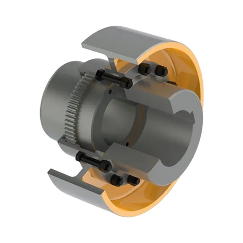
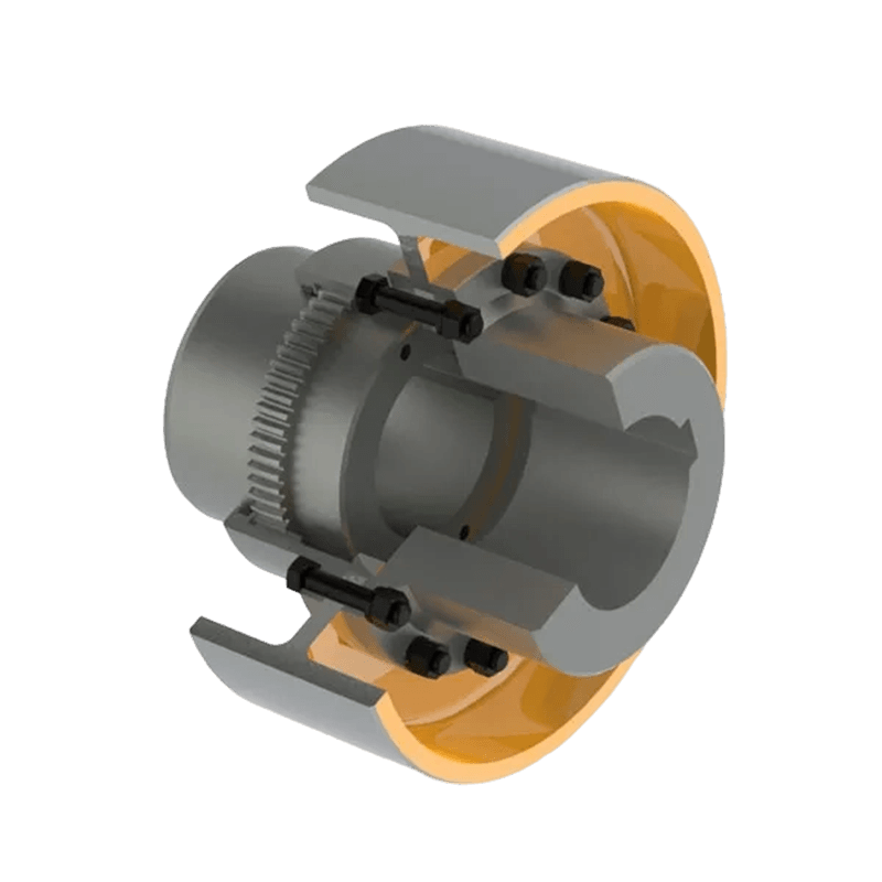
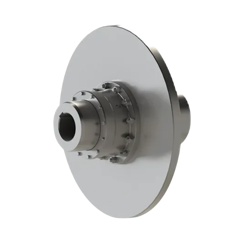
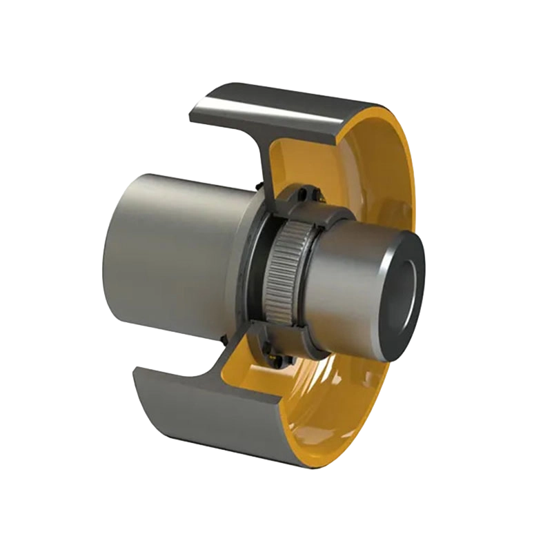
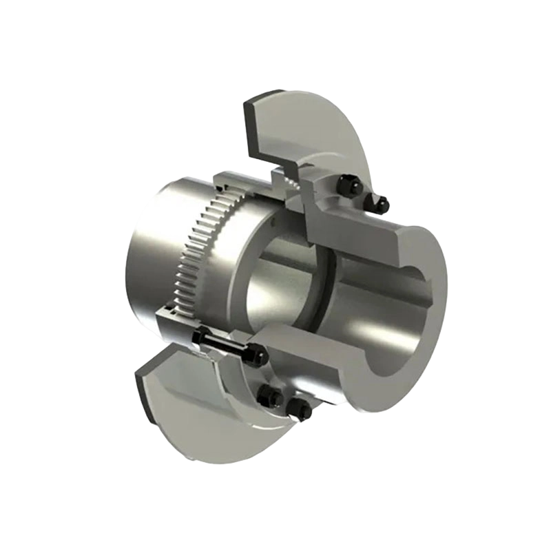
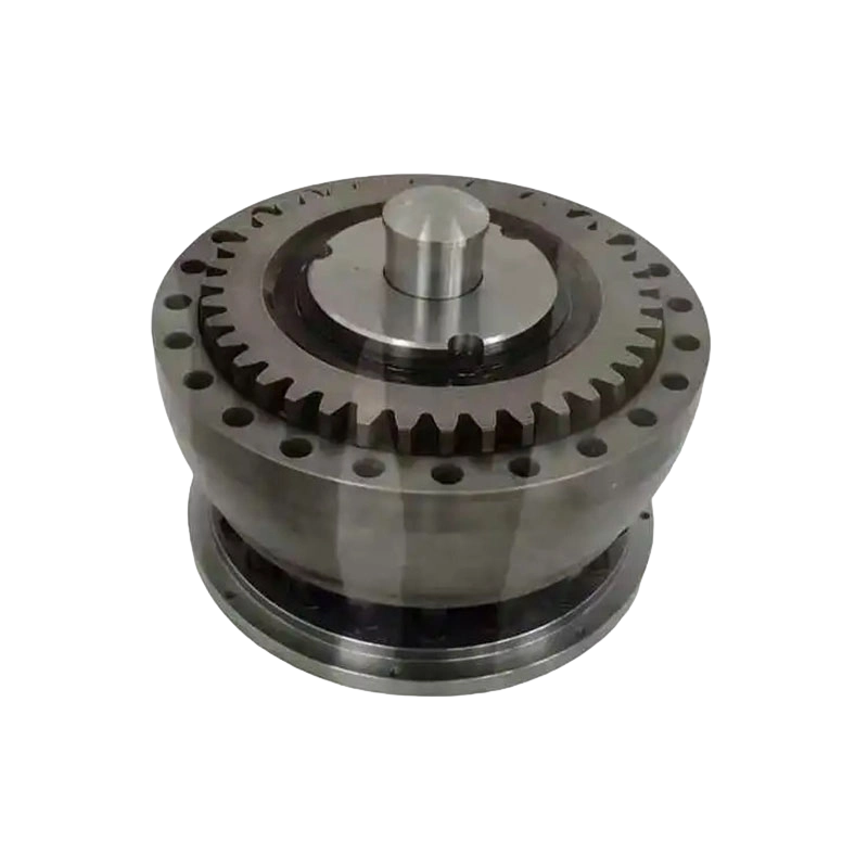
GCL Drum gear coupling with brake wheel (Q/YG 13011X-2018)
1. Product Overview and Operating Principle
The GCL coupling consists of gear-related transmission components, hubs, a housing, a brake wheel, and associated connection features. The coupling connects two shafts while allowing a controlled degree of relative movement between the shafts. This flexibility helps accommodate radial, axial, and angular misalignment that may occur because of installation tolerances, foundation movement, bearing clearance, thermal expansion, or operating deformation.
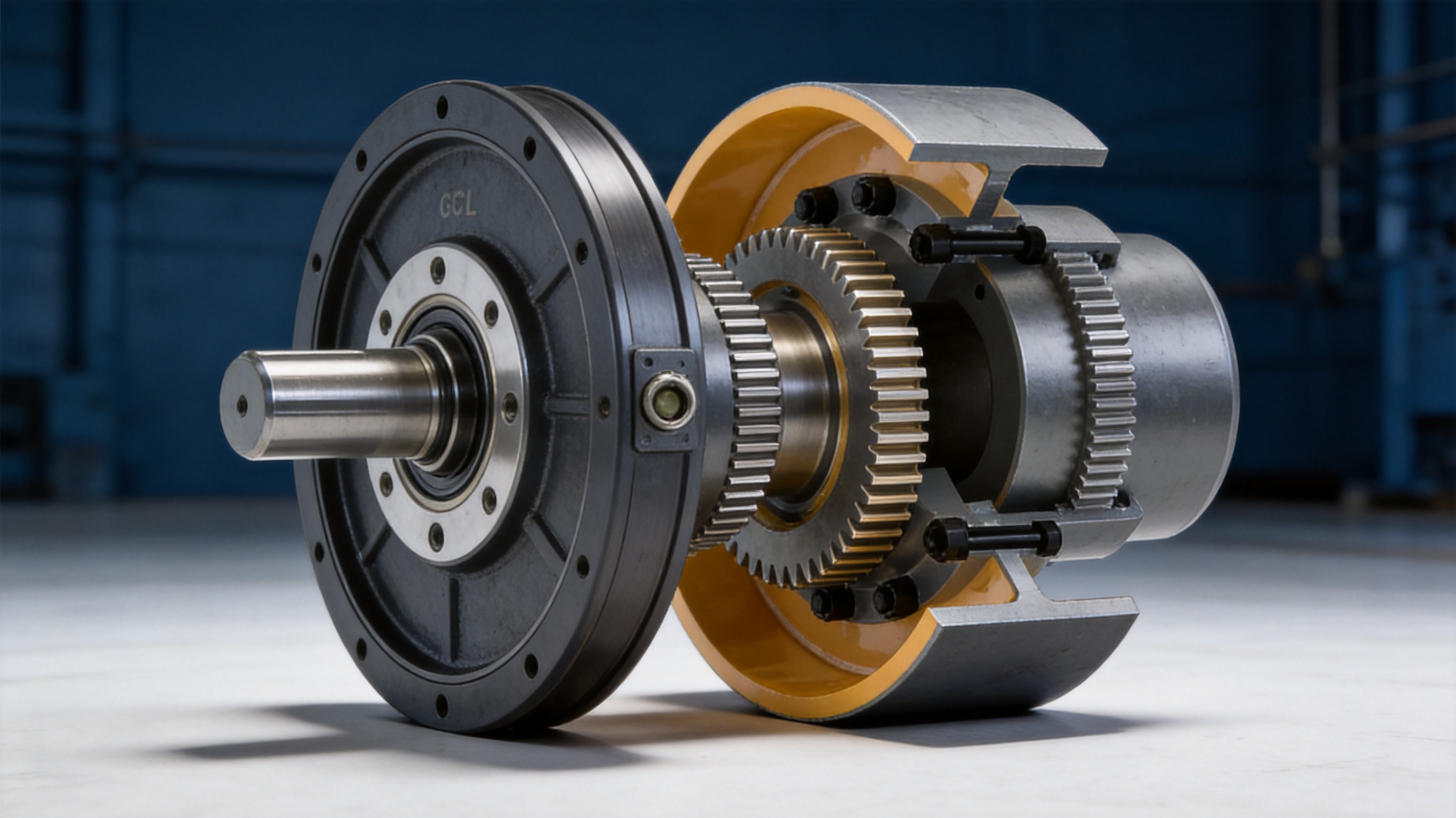
The central operating principle is based on external gear teeth engaging with internal gear teeth. One shaft drives a toothed hub, and the hub transfers torque through the gear engagement to the mating sleeve or housing connected to the second shaft. The gear geometry provides a large effective contact area and makes it possible to transmit high torque in a relatively compact package.
The drum gear arrangement is especially valuable where angular movement and radial displacement must be accommodated. Compared with a simple rigid connection, the crowned or drum-shaped tooth profile can maintain more favorable contact as the connected shafts move relative to one another. This reduces the likelihood of concentrated edge loading and helps distribute forces across the tooth flanks.
The integrated brake wheel is mounted as part of the coupling assembly. A suitable brake mechanism can act on the wheel to reduce rotational speed or hold the equipment stationary. The brake wheel does not replace the selection of a properly engineered industrial brake. Instead, it provides a purpose-designed braking interface that can be matched with the required braking torque, stopping time, duty cycle, thermal capacity, and safety arrangement.
Two principal structural arrangements are available: GCL-I and GCL-II. These arrangements provide flexibility when the machine designer must work around limited installation space, different shaft positions, or different equipment layouts. The correct form should be selected after reviewing shaft dimensions, available axial space, brake location, maintenance access, and the dynamic characteristics of the driven machine.
2. Main Design Features
2.1 Integrated torque transmission and braking
The most distinctive feature of this product is the integration of a high-capacity gear coupling and brake wheel in one assembly. This arrangement can simplify the overall drive design because the coupling and braking interface are coordinated from the beginning rather than added as unrelated components.
For a large conveyor, for example, the coupling may transmit motor torque to a gearbox or drive pulley during normal operation. When the conveyor must stop, the brake system can act on the integrated wheel. In a hoisting or lifting system, the brake can help control lowering, stopping, and load holding, subject to the complete safety design of the equipment. In a crusher or mill, it can support controlled stopping after power is removed or during inspection and maintenance procedures.
Integrating these functions can reduce the number of separate shaft-mounted components and help improve packaging. It may also reduce alignment interfaces, simplify the arrangement of guards, and make the drivetrain easier to evaluate as a complete system. The final benefit depends on the machine layout and the brake selected, but the coupling provides a purpose-built foundation for this integrated approach.
2.2 High torque capacity
The GCL series covers nominal torque ratings from 800 N·m to 180,000 N·m. This range allows the same basic product family to serve both medium-duty and very heavy industrial applications. The available sizes extend from GCL1 through GCL14, giving engineers multiple options when matching coupling capacity to motor power, shaft speed, service factor, and driven-machine characteristics.
High torque capacity is supported by the use of robust gear transmission components and a housing designed for industrial service. The coupling is intended for applications in which shock loads and cyclic torque may be significant. Nevertheless, nominal torque should not be treated as the only selection criterion. The engineer should also consider peak torque, starting torque, reversing duty, torsional vibration, braking torque, operating temperature, speed, misalignment, and the required service factor.
A properly selected coupling should normally have adequate capacity above the calculated working torque. This margin helps account for starting conditions, process fluctuations, impact loads, and changes in machine operation. For equipment such as crushers, mixers, and conveyors with large inertia, the transient torque during acceleration or blockage may be considerably higher than the steady-state running torque.
2.3 Misalignment compensation
Industrial shafts are rarely perfectly aligned under every operating condition. A machine may be aligned accurately during installation and still experience movement as the foundation settles, the temperature changes, the bearings wear, or the casing deflects under load. A flexible coupling must accommodate the expected misalignment without generating excessive forces.
The GCL gear arrangement is designed to compensate for radial, axial, and angular misalignment within the allowable limits of the selected size and installation. This flexibility helps reduce the additional stress transmitted to motors, gearboxes, bearings, and connected shafts. It can also help maintain smoother tooth contact and reduce the risk of premature wear caused by rigidly forcing shafts into an idealized position.
Misalignment compensation does not mean that alignment can be neglected. Excessive misalignment can increase tooth pressure, heat generation, lubricant degradation, vibration, and wear. Good installation practice remains essential. The coupling should be installed with shaft alignment within the specified limits, and alignment should be checked again after the equipment has reached its normal operating condition whenever thermal or structural movement is expected.
2.4 Integrated brake wheel geometry
The brake wheel is available in a range of standard diameters. Across the product series, brake wheel diameters range from approximately 160 mm to 800 mm. Different diameters permit the designer to balance braking torque, brake size, peripheral speed, installation space, and heat dissipation requirements.
A larger brake wheel can provide a greater effective braking radius, which may allow a required braking torque to be produced with a lower tangential force. However, larger dimensions also affect the mass, inertia, space envelope, and dynamic response of the complete drivetrain. For this reason, brake wheel selection must be coordinated with the braking device and the coupling size rather than made independently.
The brake wheel should be protected by an appropriate guard. The guard must prevent accidental contact, contain possible fragments, allow sufficient ventilation where required, and provide access for inspection and adjustment. The complete braking arrangement should also include the necessary fail-safe, monitoring, and emergency provisions for the specific equipment.
2.5 Lubrication access
Gear couplings depend on effective lubrication to limit friction, control wear, and protect tooth surfaces. The GCL housing includes a dedicated oil injection or grease access point that supports routine maintenance. This feature makes lubricant replenishment more convenient and reduces the need to dismantle the coupling during ordinary service.
Lubricant selection should follow the manufacturer’s technical requirements and the operating conditions of the machine. Important factors include speed, ambient temperature, load, duty cycle, contamination risk, and compatibility with sealing materials. The coupling should not be filled with an unsuitable lubricant simply because it is readily available at the plant.
Over-lubrication can also be undesirable. Excess lubricant may increase churning losses, temperature, and pressure within the housing. A controlled maintenance schedule should specify the lubricant type, quantity, replenishment interval, inspection method, and sealing procedure. If the coupling operates in a wet, dusty, or corrosive environment, the condition of seals and the cleanliness of the lubrication port deserve particular attention.
3. Technical Specifications
The GCL series includes fourteen principal sizes. The following summary presents key nominal parameters from the supplied technical data. Individual shaft-hole combinations and dimensions vary within each size, so the detailed product drawing should be consulted before final ordering.
| Model | Nominal Torque, Tn (kN·m) | Allowable Speed (r/min) | Typical Brake Wheel Diameter Options (mm) | Maximum Listed Shaft Hole Range (mm) |
|---|---|---|---|---|
| GCL1 | 0.8 | 4000 | 160, 200, 250 | 42 |
| GCL2 | 1.4 | 4000 | 200, 250, 315 | 56 |
| GCL3 | 2.8 | 4000 | 200, 250, 315 | 63 |
| GCL4 | 5.0 | 3000 | 250, 315, 400 | 80 |
| GCL5 | 8.0 | 3000 | 315, 400 | 90 |
| GCL6 | 11.2 | 3000 | 315, 400 | 100 |
| GCL7 | 16.0 | 2500 | 400, 500 | 110 |
| GCL8 | 22.4 | 2500 | 400, 500 | 125 |
| GCL9 | 28.0 | 2000 | 400, 500, 630 | 140 |
| GCL10 | 45.0 | 2000 | 400, 500, 630 | 160 |
| GCL11 | 63.0 | 1700 | 500, 630, 710 | 180 |
| GCL12 | 90.0 | 1700 | 500, 630, 710 | 200 |
| GCL13 | 125.0 | 1700 | 630, 710 | 220 |
| GCL14 | 180.0 | 1500 | 710, 800 | 260 |
The shaft-hole information in the detailed table includes Y, J1, and Z1 configurations. Depending on the model, listed shaft diameters begin at approximately 12 mm and extend to 260 mm. Shaft-hole length, hub geometry, and keyway details differ by size and bore arrangement. The ordering specification should therefore identify the complete model, structural form, shaft-hole type, bore dimensions, shaft-hole lengths, keyway requirements, brake wheel diameter, and any special balancing or coating requirements.
The supplied dimensional data also includes outside diameters, housing dimensions, axial dimensions, mass, moment of inertia, and lubricant quantities. These values are important for verifying the coupling against the available machine envelope and for calculating acceleration and braking performance. The coupling’s own moment of inertia contributes to the total rotating inertia of the drive, especially at higher speeds or in systems with frequent starts and stops.
4. Advantages Compared with Conventional Coupling Arrangements
4.1 More complete functionality than a basic flexible coupling
A conventional flexible coupling may transmit torque effectively but require a separate brake disc, brake drum, or shaft-mounted wheel. Adding an independent braking component can increase the number of parts, enlarge the shaft train, and create additional alignment and guarding requirements. The GCL solution incorporates the brake wheel into the coupling design, offering a more coordinated arrangement for machines that require both flexibility and braking.
This does not make every GCL installation automatically superior to every alternative. Disc couplings, elastomeric couplings, grid couplings, and other gear couplings each have their own strengths. The GCL design is particularly advantageous when high torque, misalignment compensation, and a mechanically accessible braking surface are required together.
4.2 Greater suitability for heavy shock loads than many elastic-element designs
Elastic-element couplings can provide torsional damping and may be highly effective in systems where vibration isolation is a primary concern. However, some high-impact industrial machines require a rigidly controlled, high-capacity gear transmission path. The GCL coupling uses metal gear components rather than relying on a polymeric or elastomeric element to carry the primary torque. This makes it well suited to heavy-duty environments where temperature, oil exposure, impact loading, or long operating periods may challenge non-metallic elements.
Because the GCL design is not dependent on an elastic insert for torque transfer, its performance is less directly affected by the aging, hardening, tearing, or fatigue modes associated with some elastomeric elements. The trade-off is that it requires correct lubrication and careful tooth inspection. The choice should always reflect the actual operating conditions.
4.3 Compact high-capacity transmission
Gear couplings can transmit high torque through a relatively compact radial envelope. The GCL series extends this advantage by combining the coupling and brake wheel in one coordinated unit. For large conveyors, hoisting machinery, and compact drive stations, reducing the number of separately mounted components can simplify layout and help preserve valuable installation space.
A compact design may also reduce the length of exposed rotating shafts. This can simplify guarding and reduce the number of potential maintenance interfaces. The final machine design must still provide adequate access for lubrication, inspection, brake adjustment, and safe removal.
4.4 Broad size and bore selection
The range from GCL1 to GCL14 gives designers a broad selection of torque and speed ratings. Multiple brake wheel diameters and shaft-hole configurations further improve adaptability. A supplier with a complete coupling portfolio can also help customers use related coupling types where the application requires a different performance characteristic, such as torsional damping, electrical isolation, or extremely low backlash.
4.5 Adaptability for non-standard applications
Industrial equipment is often developed around existing foundations, imported gearboxes, special shaft diameters, or restricted maintenance spaces. Standard couplings may not always fit without costly redesign. The manufacturer supports customized and non-standard coupling design, which can be valuable when standard dimensions do not align with the customer’s equipment.
Customization may include special bore sizes, modified shaft-hole lengths, alternative keyways, different brake wheel dimensions, protective finishes, altered mounting arrangements, or application-specific design changes. Each modification should be evaluated for strength, balance, manufacturability, lubrication, and compatibility with the applicable technical requirements.
5. Application Fields
5.1 Large conveyor systems
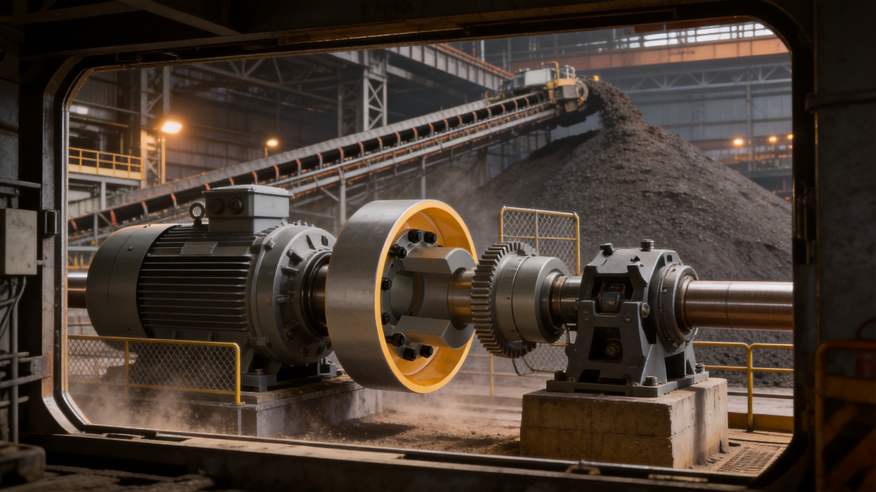
Large conveyors often have high starting inertia and may need controlled stopping when material flow must be interrupted or when an emergency occurs. The GCL coupling can transmit drive torque while providing a brake wheel for a compatible braking system. Its misalignment compensation is useful in long conveyor installations where foundations, drive frames, and gearboxes may not remain perfectly aligned over time.
Conveyor selection should account for belt acceleration, loaded and unloaded starting conditions, emergency stopping distance, downhill operation, backstopping requirements, and the consequences of a stopped belt. The coupling and brake must be sized as part of the complete conveyor drive rather than selected from motor power alone.
5.2 Crushers and mixers
Crushers, mixers, and similar machines can create fluctuating torque and impact loads. A coupling used in these systems must tolerate repeated load variation without excessive tooth stress or premature fatigue. The GCL gear arrangement provides a robust torque path for such applications, while the brake wheel can support controlled stopping during inspection, clearing, or maintenance.
For crushers, the designer should evaluate potential jam or blockage torque, reverse operation, starting frequency, and the mechanical behavior of the crusher rotor. For mixers, the material viscosity and batch variation may affect starting torque and steady-state load. A suitable service factor and torsional analysis are recommended for both types of equipment.
5.3 Mills and metallurgical equipment
Mills and metallurgical machines frequently operate continuously under high loads and in environments containing heat, dust, scale, and vibration. A gear coupling with an integrated brake wheel can provide a durable connection between the drive and driven equipment while supporting controlled stopping. Proper sealing and lubricant maintenance are especially important in these environments.
When used in steel, aluminum, or other metallurgical equipment, the coupling may be exposed to radiant heat and rapid temperature variation. The installation should include suitable thermal protection, guarding, and lubricant selection. Where water spray or cooling fluids are present, the sealing arrangement should be reviewed regularly.
5.4 Hoisting and lifting machinery
Hoisting systems require dependable torque transmission and carefully engineered braking. The GCL coupling may be used in drive arrangements for lifting, lowering, or travel mechanisms, subject to the complete design requirements of the hoisting equipment. The brake system must be capable of safely controlling the suspended load, and the coupling must be selected for the relevant duty class, acceleration cycle, emergency conditions, and load spectrum.
In safety-critical lifting applications, the coupling should not be considered the sole load-holding or safety device unless the applicable equipment design specifically permits it. Redundant braking, load monitoring, emergency power arrangements, and other protective systems may be required by the machine standard or local regulations.
5.5 Port, mining, and water equipment
Port machinery and mining equipment often combine large dimensions with harsh outdoor conditions. Dust, moisture, temperature changes, and difficult access can increase maintenance demands. The GCL coupling provides a heavy-duty transmission option with accessible lubrication and a broad range of shaft sizes.
Water equipment, including large pumps and related machinery, may have strict requirements for corrosion resistance, balance, and continuous operation. The coupling specification should address the environmental exposure, motor speed, pump torque characteristics, alignment conditions, and the possibility of water entering the housing.
6. Manufacturing Strengths and Engineering Capabilities
The product is manufactured by Zhongye Heavy Industry Technology (Zhenjiang) Co., Ltd., a company focused on the research, development, manufacturing, and sales of industrial couplings. Its product range includes toothed couplings, elastic sleeve column pin couplings, elastic column pin couplings, gear couplings with elastic pins, universal couplings, tire couplings, jaw couplings, star couplings, diaphragm couplings, drum couplings, grid couplings, Oldham couplings, flange couplings, clip-shell couplings, roller chain couplings, safety couplings, and customized coupling solutions.
This broad product portfolio is an advantage for customers whose equipment includes several types of drives. Instead of treating each coupling as an isolated purchase, the customer can obtain application support across different transmission technologies. A coupling manufacturer with experience in both flexible and rigid arrangements is better positioned to compare torsional flexibility, misalignment capacity, braking requirements, speed, maintenance, and installation constraints.
The company’s new workshop covers approximately 16,463.52 square meters. It includes a heavy workshop of approximately 5,500 square meters, a precision workshop of approximately 4,600 square meters, an office building and gymnasium, a dining hall, a warehouse, and designated road, greening, and parking areas. This layout supports the separation of heavy processing, precision manufacturing, storage, technical work, and administration.
6.1 Heavy-duty processing capability
Large GCL models require the handling of substantial metal components. A heavy workshop provides the working space and equipment environment needed for large housings, hubs, brake wheels, and related components. Heavy-duty manufacturing capability is important because dimensional stability, handling safety, and process control become increasingly significant as component size and mass increase.
The production sequence for a heavy coupling generally begins with engineering review and material preparation. Components are then produced through appropriate machining and forming processes, followed by heat treatment or material conditioning where specified. Gear surfaces, bores, keyways, mounting faces, and sealing locations require controlled machining because errors in these areas can affect alignment, tooth contact, balance, and service life.
6.2 Precision workshop and dimensional control
The precision workshop supports the production of parts that require tighter dimensional control, including gear teeth, shaft bores, bearing or sealing surfaces, and mating interfaces. Precision is essential in a gear coupling because excessive dimensional deviation can alter tooth contact and concentrate load at the edges of the gear teeth.
Inspection should verify critical dimensions against the approved drawings and technical requirements. Typical inspection activities may include bore measurement, shaft-hole length verification, keyway inspection, runout measurement, tooth profile evaluation, surface condition checks, and dimensional matching of mating components. Where the application requires it, dynamic balancing and additional testing can be incorporated into the manufacturing plan.
6.3 Process control from engineering to shipment
A reliable coupling manufacturer must control more than the final machining step. Product quality is influenced by design interpretation, raw material traceability, process planning, equipment condition, operator skill, inspection methods, assembly practice, lubrication, packaging, and transport protection. A structured production system helps ensure that the selected model is manufactured consistently.
The company emphasizes strong research and development, manufacturing capability, testing facilities, strict quality control, complete specifications, customization support, technical assistance before sale, and after-sale service. These strengths are particularly relevant for large industrial couplings because the cost of an incorrect selection or premature failure can exceed the original component price by many times through downtime, lost production, secondary damage, and emergency labor.
6.4 Custom design and non-standard manufacturing
Customization is an important capability for coupling applications. Customers may need a non-standard bore, a special shaft extension, an unusual brake wheel diameter, a modified housing, a different coating, or a coupling designed around an existing machine. The manufacturer’s experience with multiple coupling categories supports the development of application-specific solutions.
A sound custom design process should begin with complete operating data. This includes motor power, rated speed, starting method, driven-machine torque, peak torque, reversing frequency, shaft diameters, shaft lengths, key details, misalignment, ambient conditions, installation orientation, braking torque, stopping time, and maintenance limitations. The supplier can then evaluate the required coupling size and propose a suitable configuration.
7. Material, Gear, and Housing Considerations
The internal gear components are described as being made from high-strength materials such as alloy steel. Material selection is important because the gear teeth must withstand repeated contact stress, bending stress, impact, and sliding under conditions that may change during operation.
Heat treatment, when included in the approved manufacturing process, can improve the hardness, strength, wear resistance, and fatigue performance of the gear surfaces. The exact treatment should be confirmed in the product documentation for the selected model. Surface hardness alone is not enough to guarantee performance; tooth geometry, core toughness, alignment, lubrication, surface finish, and manufacturing accuracy are equally important.
The housing protects the gear engagement and retains lubricant. It must provide adequate structural strength while maintaining the required relationship between the mating components. Sealing surfaces should limit lubricant leakage and help exclude contaminants. In dusty or wet environments, inspection of the housing and seals should be part of the preventive maintenance program.
The brake wheel must also be manufactured with appropriate dimensional accuracy and surface condition. Runout, balance, mounting concentricity, and surface integrity affect brake contact and vibration. The brake wheel and brake mechanism should be installed according to the approved drawing and checked after assembly.
8. Selection Guidelines
8.1 Calculate the working torque
The first selection step is to calculate the actual operating torque. For a rotating drive, torque can be related to power and speed using the appropriate engineering relationship. The calculated torque should then be adjusted for the machine’s service factor, starting conditions, impact loads, operating cycle, and environmental conditions.
Machines with relatively uniform loads may require a lower service factor than machines with severe shock, frequent starts, reversing operation, or intermittent blockage. Crushers, mills, bucket conveyors, and certain hoisting applications generally require more careful evaluation than continuously running pumps or fans.
8.2 Check speed and peripheral velocity
The allowable speed listed for each GCL model decreases as coupling size increases. GCL1 through GCL3 are listed with allowable speeds up to 4,000 r/min, while larger models have lower allowable speeds, reaching 1,500 r/min for GCL14. The operating speed must remain within the permissible value for the selected configuration.
The brake wheel’s peripheral speed also deserves attention. A larger wheel rotating at high speed can generate significant surface velocity and energy. Brake selection, wheel balance, guarding, and thermal calculations should be coordinated with the operating speed and stopping duty.
8.3 Confirm shaft and bore compatibility
The shaft-hole type may be Y, J1, or Z1, with different bore dimensions and shaft-hole lengths. The customer should provide accurate shaft measurements rather than relying on nominal shaft size. Important information includes actual diameter, keyway width and depth, shaft extension, end clearance, shoulder location, and any taper or special fit.
Incorrect bore or keyway details can cause installation delays, poor torque transfer, excessive fretting, or unsafe loosening. When existing equipment is being refurbished, the coupling should be checked against the actual shaft condition, including wear, corrosion, deformation, and previous keyway modifications.
8.4 Evaluate misalignment
Radial, axial, and angular misalignment should be measured or estimated for both the initial installation and normal operation. The coupling’s flexibility is intended to accommodate permitted movement, not to compensate for poor assembly. If the expected misalignment exceeds the allowable value, the machine foundation, bearing arrangement, shaft alignment, or coupling type may need to be reconsidered.
8.5 Match the braking requirement
The braking system must be evaluated for normal stopping, emergency stopping, holding, heat generation, and repeated operation. Required braking torque depends on the rotating inertia, speed, load direction, acceleration, stopping time, and mechanical losses. The coupling’s brake wheel diameter and mounting arrangement should be selected to suit the brake.
The designer should also consider whether the brake must be spring-applied, hydraulically released, electrically released, or otherwise fail-safe. Brake control, monitoring, and emergency circuits are part of the machine safety system and must be designed in accordance with the relevant requirements.
9. Installation Practices
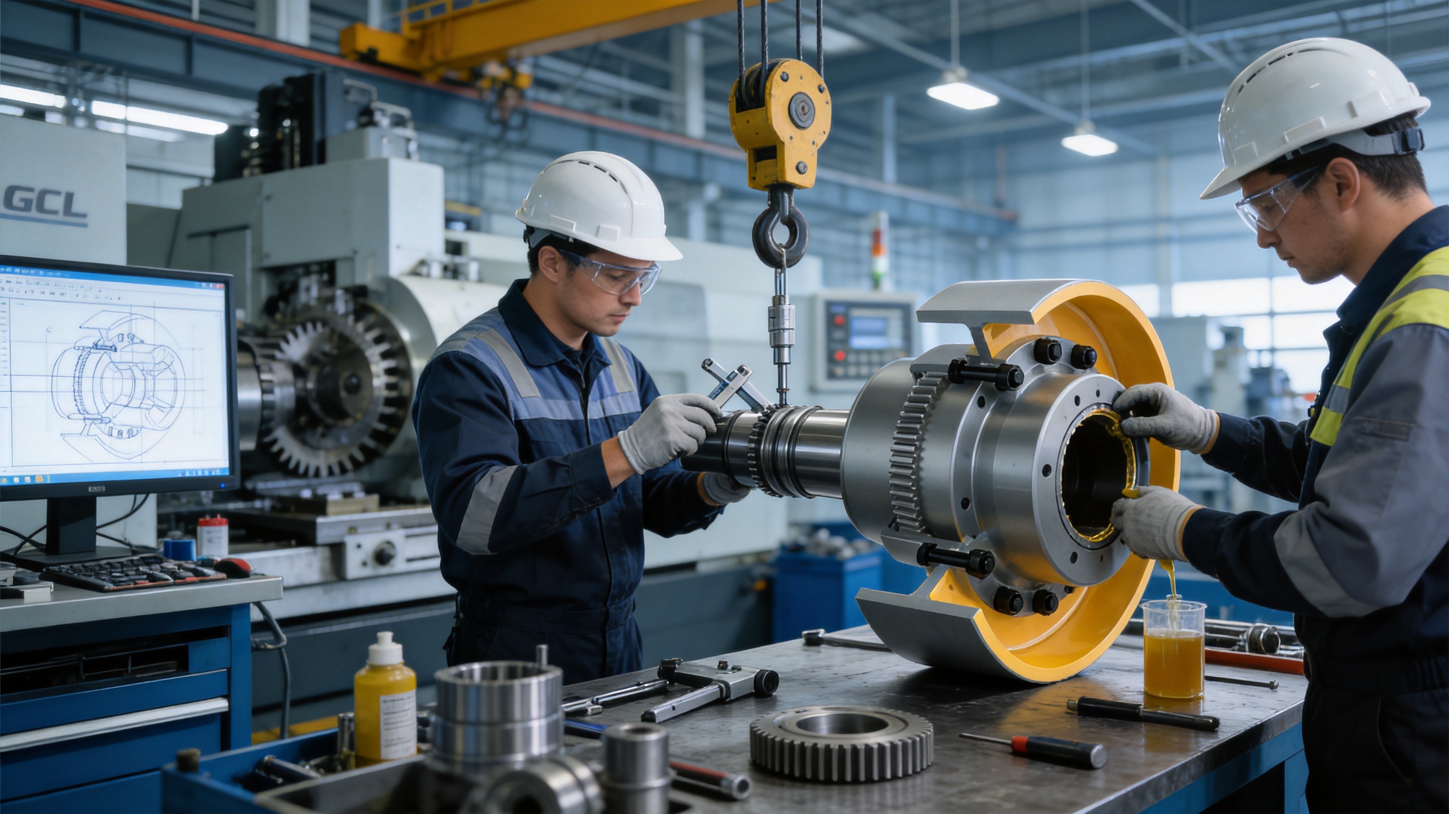
Before installation, inspect the coupling, brake wheel, shafts, keys, fasteners, seals, and protective packaging. Confirm that the model and bore dimensions correspond to the approved order. Remove dirt, rust-preventive residue, and foreign material from mating surfaces without damaging precision fits.
Check the shaft alignment using suitable measurement equipment. The coupling should be installed on clean, properly prepared shafts. Keys must fit correctly and should not be forced in a way that distorts the hub. Heating may be used for interference-fit installation only when approved procedures are followed and seals, lubricant, and material properties are protected.
Install the GCL-I or GCL-II arrangement according to the correct drawing. Ensure that the required axial position and end clearances are maintained. Tighten fasteners using the specified sequence and torque. After assembly, rotate the shaft manually when possible to confirm that there is no binding, interference, or abnormal resistance.
The brake must be aligned with the wheel so that contact is uniform and the mechanism does not drag during normal running. Verify that the brake wheel is concentric and that the brake guard is secure. The final installation should include a low-speed or no-load trial, followed by a controlled operating test.
During commissioning, monitor vibration, temperature, noise, lubricant leakage, brake response, and shaft movement. A short initial inspection after operation can identify loose fasteners, settling, unexpected contact, or alignment changes before the equipment is placed into full production.
10. Maintenance and Service Life
Routine maintenance is essential to obtain the expected service life from a gear coupling. Maintenance personnel should establish inspection intervals based on operating hours, starts and stops, load severity, environmental contamination, and the consequences of failure.
Visual inspections should look for lubricant leakage, damaged seals, loose fasteners, corrosion, abnormal wear, brake wheel damage, and guard problems. Unusual noise or vibration may indicate insufficient lubrication, tooth wear, misalignment, loose mounting, bearing problems, or a brake issue. Any abnormal condition should be investigated rather than corrected only by adding lubricant.
Lubricant should be replenished through the dedicated access point using the correct product and quantity. Before opening the lubrication port, clean the surrounding area to prevent contamination from entering the housing. If the coupling is disassembled, inspect gear teeth for pitting, scoring, cracking, plastic deformation, or unusual contact patterns.
Tooth wear often provides useful information about the machine. Wear concentrated at one side of the tooth may indicate angular or radial misalignment. Surface scoring may suggest inadequate lubrication or contamination. Pitting may be associated with contact fatigue or excessive load. A comprehensive inspection should record findings and compare them with previous service records.
The brake wheel should be checked for surface damage, excessive wear, cracks, runout, and secure attachment. The brake mechanism should be inspected separately for lining condition, actuator performance, spring or hydraulic condition, release clearance, and control-system response. Coupling maintenance and brake maintenance should be coordinated but not treated as the same inspection task.
Before maintenance, isolate and lock out all energy sources. The machine must be prevented from starting, and any suspended or stored mechanical energy must be secured. Guards should be removed only by authorized personnel and replaced before the equipment returns to service.
11. Reliability, Safety, and Lifecycle Value
The value of an industrial coupling is determined not only by its purchase price but also by its reliability, serviceability, compatibility, and effect on total equipment operation. A coupling that is correctly selected and maintained can help reduce unplanned downtime and protect more expensive components such as motors, gearboxes, shafts, and bearings.
The GCL design contributes to lifecycle value through its heavy-duty gear transmission, integrated brake wheel, lubrication access, broad model range, and ability to support customized configurations. The integrated arrangement may reduce the number of separate components and simplify the transmission layout. High torque capacity can also permit the coupling to be used in demanding applications without resorting to multiple smaller components.
Safety benefits arise from the ability to provide controlled stopping through a compatible brake. However, safe operation depends on the entire machine system. Correct brake sizing, guarding, emergency control, maintenance, inspection, and operator procedures remain necessary. No coupling should be selected without considering the applicable machinery, electrical, lifting, conveyor, and workplace safety requirements.
12. Why Work with an Experienced Coupling Manufacturer
Coupling selection often requires more than choosing a catalog number. The manufacturer must understand the relationship between torque, speed, misalignment, bore design, gear tooth stress, brake geometry, lubrication, and installation. An experienced supplier can help identify whether a standard GCL configuration is sufficient or whether a customized version is more appropriate.
Zhongye Heavy Industry Technology combines product development, manufacturing, sales, technical support, and after-sale service. Its experience covers many coupling technologies and multiple industrial sectors, including metallurgy, mining, water equipment, lifting equipment, paper machinery, port machinery, and other heavy industrial applications.
The company’s engineering and manufacturing resources support both standard products and non-standard designs. This is important for original equipment manufacturers, maintenance contractors, engineering companies, and end users managing replacement projects. A replacement coupling may need to fit an existing shaft arrangement exactly, while a new machine may benefit from an optimized coupling and brake-wheel configuration developed during the design stage.
Quality control and testing are also important when supplying large rotating components. Customers should expect technical drawings, material and process information where applicable, dimensional inspection, assembly verification, and documentation appropriate to the project. For critical applications, additional requirements such as balancing records, inspection reports, or special acceptance tests can be discussed before production.
13. Recommended Technical Information for an Inquiry
To obtain an accurate recommendation, the customer should provide the motor power, rated speed, driven-machine type, working torque, peak torque, service factor, starting method, reversing frequency, operating temperature, ambient conditions, and expected working hours.
The inquiry should also include the two shaft diameters, shaft-hole lengths, keyway dimensions, shaft extension, distance between shaft ends, required coupling form, available installation space, preferred brake wheel diameter, braking torque, stopping time, brake type, and guarding limitations.
Photographs, existing coupling drawings, gearbox data sheets, foundation drawings, and maintenance records can be helpful when replacing an installed coupling. If the equipment has experienced repeated coupling failures, the failure history should be provided. Repeated failures may result from misalignment, inadequate lubrication, excessive torque, torsional resonance, incorrect bore fits, brake drag, or an unsuitable coupling type.
Providing complete data at the beginning helps the manufacturer evaluate the application more efficiently and reduces the risk of late-stage dimensional changes. It also allows the coupling, brake, shaft, and guard to be reviewed as one mechanical system.
14. Frequently Asked Questions
Q1: What is the primary function of the GCL drum gear coupling with brake wheel?
Its primary function is to transmit high torque between two shafts while accommodating permitted misalignment and providing an integrated brake wheel for controlled deceleration or stopping. It is intended for industrial machinery requiring both heavy-duty drive transmission and braking capability.
Q2: What standard applies to this product?
The product is identified as a GCL type drum gear coupling with brake wheel manufactured according to Q/YG 13011X-2018. The exact technical requirements, dimensions, tolerances, and ordering details should be confirmed against the applicable product drawing and documentation.
Q3: What torque range does the GCL series cover?
The supplied product information identifies nominal torque ratings from 800 N·m to 180,000 N·m, corresponding to GCL1 through GCL14. Selection must also consider service factor, peak torque, shock loading, speed, braking duty, and misalignment.
Q4: What are the allowable speeds?
Allowable speed depends on the model. The listed range reaches 4,000 r/min for smaller sizes and decreases to 1,500 r/min for GCL14. The selected coupling must remain within the allowable speed for its complete configuration, including the brake wheel and bore arrangement.
Q5: Which shaft-hole types are available?
The technical information lists Y, J1, and Z1 shaft-hole configurations. Available bore diameters and shaft-hole lengths vary by model. Customers should provide precise shaft and keyway details before final selection.
Q6: Can the coupling compensate for shaft misalignment?
Yes. The drum gear design is intended to compensate for permitted radial, axial, and angular misalignment. It does not eliminate the need for accurate installation. Excessive misalignment can increase tooth loading, heat, vibration, and wear.
Q7: Does the product include the complete brake system?
The product includes an integrated brake wheel, but the complete braking system must be matched separately to the application. Brake torque, actuator type, stopping time, thermal capacity, safety function, control circuit, and guarding must be evaluated by the machine designer.
Q8: How is the coupling lubricated?
The housing includes a dedicated lubrication access point for routine grease or oil replenishment as specified by the manufacturer. The correct lubricant type and quantity should be used, and the lubrication port should be cleaned before service.
Q9: Is the GCL coupling suitable for conveyors?
It is suitable for many heavy conveyor drive applications, including systems requiring controlled or emergency stopping. The complete conveyor design must evaluate belt inertia, loaded starting, downhill operation, emergency stopping distance, brake capacity, and backstop requirements.
Q10: Can the manufacturer provide customized couplings?
Yes. The company undertakes the design and manufacture of non-standard couplings. Customization may involve bores, shaft-hole lengths, keyways, brake wheel dimensions, mounting arrangements, coatings, or other application-specific features, subject to engineering review.
Q11: What information is needed for customized design?
Useful information includes power, speed, torque, peak torque, shaft dimensions, shaft spacing, misalignment, brake torque, stopping time, environment, installation orientation, operating cycle, and available space. Drawings and photographs of the existing equipment are also valuable.
Q12: What industries use this type of coupling?
Typical fields include conveying, metallurgy, mining, lifting, ports, water conservancy machinery, crushers, mixers, mills, and other heavy industrial equipment. Suitability depends on the actual mechanical and environmental conditions.
Q13: How can service life be extended?
Service life can be improved through accurate alignment, correct installation, proper lubrication, regular inspection, brake maintenance, contamination control, vibration monitoring, and prompt investigation of abnormal noise or temperature. The coupling should be operated within its torque, speed, and misalignment limits.
Q14: What makes this design different from an elastomeric coupling?
The GCL coupling uses gear transmission and a metal brake wheel rather than relying on a non-metallic elastic element for primary torque transfer. It is therefore particularly suited to high torque, heavy shock, and harsh industrial applications where a robust gear connection is preferred. Elastomeric couplings may be more appropriate where torsional damping is the dominant requirement.
15. Conclusion
The GCL drum gear coupling with brake wheel is a specialized industrial transmission component designed to combine high torque capacity, flexible shaft connection, and braking functionality. Its GCL1 to GCL14 size range, multiple bore configurations, broad brake wheel selection, lubrication access, and two structural forms allow it to serve a wide variety of demanding applications.
Its principal advantage over a basic coupling arrangement is the coordinated integration of torque transmission and braking. This can simplify machine layout, support controlled stopping, reduce the number of separately mounted shaft components, and provide a practical solution for conveyors, crushers, mills, mixers, hoisting systems, metallurgical machinery, mining equipment, port machinery, and water equipment.
The product’s performance ultimately depends on correct engineering selection and maintenance. Torque, speed, misalignment, shaft dimensions, braking requirements, lubrication, environment, and safety provisions must all be considered. When these factors are properly evaluated, the GCL coupling can provide a dependable connection for heavy industrial machinery.
Supported by research and development, heavy and precision workshop resources, testing capability, quality control, broad coupling experience, and customization support, Zhongye Heavy Industry Technology is positioned to provide more than a standard catalog component. It can support customers from initial application review through engineering design, manufacturing, inspection, delivery, installation guidance, and after-sale service. For industrial users seeking a durable coupling and integrated brake-wheel solution, the GCL series offers a strong foundation for reliable power transmission and controlled machine operation.
References
1. Q/YG 13011X-2018, Technical Requirements for GCL Type Drum Gear Couplings with Brake Wheel.
2. GCL Type Drum Gear Coupling with Brake Wheel, Product Overview and Basic Parameters, supplied technical product information.
3. Industrial Gear Coupling Design Principles, including torque transmission, tooth contact, lubrication, and misalignment considerations.
4. Machinery Coupling Selection Practice, guidance on service factors, shaft fit, alignment, speed, and operating conditions.
5. Industrial Brake Application Principles, including braking torque, stopping time, thermal duty, guarding, and maintenance.
6. ISO 9001 Quality Management Systems, general principles for controlled manufacturing and quality assurance.
Product: GCL Drum gear coupling with brake wheel (Q/YG 13011X-2018)
- Quick Links
- About
- Products
- Our Service
- News & Events
- Contact
- Products Series
- Flexible Couplings with Non-Elastic Elements
- Flexible Couplings with Metal Elastic Elements
- Flexible Couplings with Non-Metallic Elastic Elements
- Safety Coupling
- Rigid Coupling
- Contact Us
- Tel : +86 511 8572 3800 +86 511 8572 3900
- Mobile : +86 15106109009
- Email : sales@couplingzy.com
- Add:No.1 Zhongye Yingbin Avenue, Gaozi Street, Dantu Economic Development Zone, Zhenjiang City, Jiangsu Province, China.


