:+86 15106109009
:sales@couplingzy.com


 English
 русский
 Español
 عربى
 Português
 Deutsch
 Türk
 Indonesia


Large-Size Standard Telescopic Flange Universal Coupling for Heavy-Duty Power Transmission
Content
- 1 1. The Role of a Large-Size Universal Coupling
- 2 2. Product Design and Operating Principle
- 3 3. Main Technical Specifications
- 4 4. Advantages Over Conventional Coupling Solutions
- 5 5. Application Areas
- 6 6. Manufacturing Strengths and Engineering Capabilities
- 7 7. Installation and Commissioning Considerations
- 8 8. Maintenance and Service Life
- 9 9. Selection Guide
- 10 10. Why the SWC-BF Series Is a Competitive Choice
- 11 11. Customization and Technical Support
- 12 12. Frequently Asked Questions
- 12.1 What is the primary function of the SWC-BF coupling?
- 12.2 What does “telescopic” mean in this coupling?
- 12.3 What is the largest available model?
- 12.4 Can the coupling operate at 15°?
- 12.5 Is this coupling suitable for steel mill equipment?
- 12.6 Is it suitable for mining crushers?
- 12.7 Does the coupling eliminate the need for alignment?
- 12.8 How should the model be selected?
- 12.9 Can a non-standard version be manufactured?
- 12.10 What information is needed for a quotation?
- 12.11 What industries does the manufacturer serve?
- 12.12 What support is available after purchase?
- 13 13. Conclusion
- 14 References
- 15 Product: SWC-BF large size standard expansion flange universal coupling
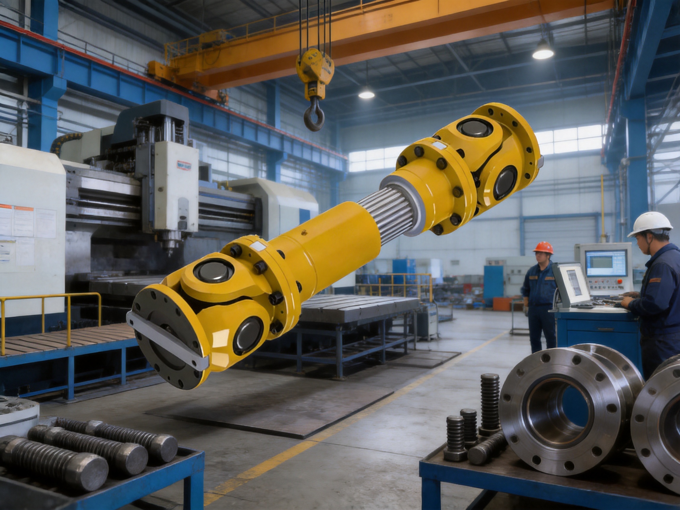
Large industrial machines require coupling systems that can transmit substantial torque while accommodating the movement and deformation that naturally occur during operation. In steel production, mining, power generation, shipbuilding, lifting equipment, and other heavy-duty applications, shafts are rarely exposed to perfectly aligned and completely static conditions. Thermal expansion, foundation settlement, frame distortion, installation tolerances, angular misalignment, and axial movement can all affect the connected equipment. A coupling that cannot compensate for these conditions may transfer excessive loads into bearings, gears, shafts, and housings.
The SWC-BF large-size standard telescopic flange universal coupling is designed for this demanding operating environment. It combines high-capacity torque transmission with angular displacement compensation and axial expansion and contraction. Its universal-joint configuration allows connected shafts to operate with a controlled angular deviation, while its telescopic flange structure provides a practical solution for axial movement. The result is a robust connection for large machines that need reliable power transmission under changing mechanical conditions.
Available in sizes from SWC620BF to SWC1320BF, the series covers turning diameters from 620 mm to 1,320 mm. Depending on the model and operating angle, nominal torque ratings extend up to 16,000 kN·m, while fatigue torque ratings reach up to 9,600 kN·m. The product range is therefore suitable for large-scale systems in which ordinary rigid couplings or smaller flexible couplings cannot provide an appropriate combination of strength, displacement compensation, and service life.
1. The Role of a Large-Size Universal Coupling
A universal coupling is used to connect two shafts whose centerlines may not remain perfectly aligned. Unlike a simple rigid flange connection, it allows controlled angular movement between the connected shafts. This capability is essential in long shaft lines, rolling equipment, converters, crushers, large pumps, marine propulsion arrangements, and other installations where the shafts are separated by a considerable distance or installed on structures that experience movement.
The coupling transfers torque from the driving machine to the driven machine through a mechanical connection designed to maintain effective power transmission while compensating for certain types of misalignment. It does not eliminate the need for correct shaft alignment, proper foundation design, or suitable operating procedures. Instead, it provides a controlled tolerance for the movements that remain after careful engineering and installation.
The SWC-BF design adds axial expansion and contraction capability to the universal coupling function. This is particularly useful when the distance between machines changes during operation. Temperature changes can cause shafts, housings, and machine frames to expand or contract. In large equipment, even a moderate temperature change can produce significant axial movement over a long center distance. If this movement is blocked, the resulting thrust may overload bearings or create stress in the connected machine structures.
By allowing telescopic movement through the standard expansion flange arrangement, the coupling helps absorb these changes. The coupling can continue transmitting torque while accommodating a specified expansion and contraction quantity. This makes it an effective connection solution for large industrial systems with demanding mechanical and thermal conditions.
2. Product Design and Operating Principle
2.1 Universal-joint configuration
The basic operating principle is based on a universal-joint arrangement that permits angular displacement between the connected shafts. The coupling is designed to operate within an axis angle range of 5°, 10°, or 15°, depending on the selected application condition and model. The allowable operating angle influences the torque and fatigue torque values, bearing life factor, and dimensional arrangement.
At a lower axis angle, the coupling generally provides its highest rated torque and fatigue torque for a given model. As the angle increases, the permissible torque and calculated bearing life factor change. This is a normal characteristic of universal coupling operation because angular movement affects the kinematics, load distribution, bearing forces, and contact conditions within the assembly.
The available technical data lists each model at three representative operating angles. This gives designers a practical basis for selecting a coupling according to both the required torque and the expected shaft geometry. Instead of selecting only by outside diameter or nominal shaft size, engineers can evaluate the complete operating condition, including torque, angle, axial movement, dimensions, and service requirements.
2.2 Telescopic expansion flange
The telescopic flange arrangement is one of the principal features of the SWC-BF series. It provides an axial expansion and contraction quantity of 250 mm, 300 mm, or 350 mm, depending on the model. This movement allowance enables the coupling to accommodate changes in shaft spacing caused by thermal expansion, cold contraction, structural deformation, and installation conditions.
A conventional rigid flange coupling can transmit torque effectively when the shafts are correctly aligned and their relative position remains constant. However, it has little ability to absorb axial movement. A non-telescopic connection may therefore impose unwanted axial loads on the machine bearings and structures. The telescopic design addresses this limitation while maintaining a large, rigid torque path suitable for heavy machinery.
The expansion and contraction allowance must be considered during equipment layout and installation. The available movement should be sufficient for the calculated thermal and structural displacement, but the coupling should not be forced to operate continuously at the end of its movement range. Proper installation should ensure that the coupling has suitable working clearance and that adjacent components do not interfere with the telescopic action.
2.3 Flange connection and high-capacity torque path
The flange connection provides a broad and stable interface between coupling components and the connected shafts or machine assemblies. The listed flange dimensions include bolt-hole patterns such as 20 × diameter 26 mm, 24 × diameter 26 mm, 24 × diameter 33 mm, 24 × diameter 39 mm, 20 × diameter 45 mm, 20 × diameter 52 mm, and 24 × diameter 52 mm, depending on the model.
These large bolt patterns are consistent with the intended application in heavy equipment. A correctly engineered flange connection distributes torque and reaction forces over multiple fasteners and a substantial contact area. This helps reduce local stress concentration and supports the transmission of high torque under cyclic loading. Fastener selection, tightening procedure, flange face condition, and inspection remain important to the performance of the complete assembly.
The high-capacity torque path is supported by a large turning diameter ranging from 620 mm to 1,320 mm. The larger models are intended for systems with exceptionally high torque requirements. The SWC1320BF, for example, has a nominal torque rating of 16,000 kN·m at the listed 5° operating condition and a fatigue torque rating of 9,600 kN·m. Such capacity allows the coupling to be considered for large production lines, heavy crushers, major conveying systems, and other high-power installations.
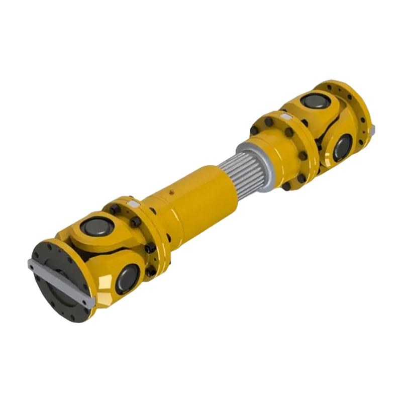
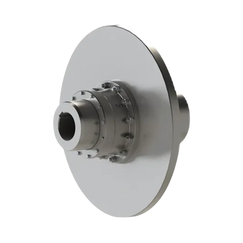
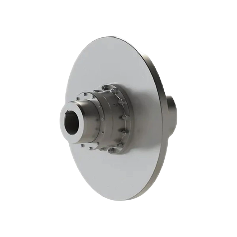
SWC-BF large size standard expansion flange universal coupling
3. Main Technical Specifications
The product family includes ten principal models: SWC620BF, SWC680BF, SWC740BF, SWC780BF, SWC840BF, SWC920BF, SWC1000BF, SWC1100BF, SWC1200BF, SWC1280BF, and SWC1320BF. The model number generally corresponds to the nominal turning diameter in millimeters.
The smallest listed model has a turning diameter of 620 mm, a nominal torque of 1,600 kN·m at 5°, and a fatigue torque of 960 kN·m at 5°. The largest listed model has a turning diameter of 1,320 mm, a nominal torque of 16,000 kN·m at 5°, and a fatigue torque of 9,600 kN·m at 5°. This broad capacity range enables engineers to select a coupling that matches the required load without automatically oversizing every installation.
| Model | Turning Diameter (mm) | Nominal Torque at 5° (kN·m) | Fatigue Torque at 5° (kN·m) | Expansion and Contraction (mm) |
|---|---|---|---|---|
| SWC620BF | 620 | 1,600 | 960 | 250 |
| SWC680BF | 680 | 2,180 | 1,310 | 250 |
| SWC740BF | 740 | 2,800 | 1,680 | 250 |
| SWC780BF | 780 | 3,200 | 1,920 | 250 |
| SWC840BF | 840 | 3,600 | 2,160 | 250 |
| SWC920BF | 920 | 5,300 | 3,200 | 300 |
| SWC1000BF | 1,000 | 6,900 | 4,140 | 300 |
| SWC1100BF | 1,100 | 9,200 | 5,520 | 300 |
| SWC1200BF | 1,200 | 12,000 | 7,200 | 300 |
| SWC1280BF | 1,280 | 14,600 | 8,760 | 350 |
| SWC1320BF | 1,320 | 16,000 | 9,600 | 350 |
The values in the table represent the principal 5° operating-angle condition. For detailed engineering, the rated values at 10° and 15° must also be considered. The technical data shows that torque and fatigue torque decrease as the axis angle increases. This relationship is important when the coupling is installed in an arrangement with substantial angular deviation.
3.1 Performance at different axis angles
The SWC620BF provides nominal torque values of 1,600 kN·m, 1,400 kN·m, and 1,220 kN·m at 5°, 10°, and 15° respectively. Its corresponding fatigue torque values are 960 kN·m, 840 kN·m, and 730 kN·m. The same selection principle applies throughout the product family.
For the SWC1320BF, the nominal torque values are 16,000 kN·m at 5°, 13,900 kN·m at 10°, and 12,000 kN·m at 15°. The corresponding fatigue torque values are 9,600 kN·m, 8,340 kN·m, and 7,200 kN·m. These figures show that the largest model retains substantial torque capacity even when operating at the highest listed axis angle.
Designers should use the actual working angle rather than the maximum possible angle when calculating the required coupling size. If the installation may experience varying angular conditions, the highest credible continuous and transient angle should be included in the selection process. Shock loads, starts and stops, reversing operation, load fluctuations, and emergency conditions may also require additional engineering analysis.
3.2 Bearing life factor
The technical table includes a bearing life factor designated as K. The values increase significantly with model size, ranging from 0.13 × 10⁶ to 288 × 106 across the listed operating conditions. The K value changes with axis angle and is intended to support bearing-life evaluation in conjunction with the actual load, speed, angle, lubrication, operating cycle, and maintenance conditions.
A bearing life factor should not be interpreted as a guaranteed service life without a complete calculation. Actual bearing performance depends on many factors, including radial and axial loads, rotational speed, contamination, lubrication quality, alignment, vibration, temperature, and the frequency of angular movement. However, the inclusion of this factor provides useful technical information for preliminary design and comparative selection.
3.3 Principal dimensions
The data includes Lmin, D1 with jS11 tolerance, D2 with H7 tolerance, D3, Lm, bolt-hole arrangement, and k. These dimensions allow the coupling to be evaluated against available installation space, shaft geometry, flange design, and maintenance access.
For example, the SWC620BF has an Lmin value of 3,100 mm at 5°, with associated length values of 3,180 mm and 3,220 mm at the listed angle conditions. Its D1 dimension is 575 mm at 5°, 500 mm at 10°, and 480 mm at 15°, while the D2 dimension is 325 mm, 345 mm, and 355 mm in the corresponding arrangement shown in the technical data. Larger models have progressively larger dimensions and bolt patterns.
Because large universal couplings are substantial mechanical assemblies, dimensional planning is essential. The engineer should reserve adequate clearance for installation, inspection, lubrication, bolt access, telescopic movement, and component replacement. The coupling should also be protected from unnecessary contact with guards, supports, foundations, piping, and adjacent rotating parts.
4. Advantages Over Conventional Coupling Solutions
4.1 Higher accommodation of axial movement
One of the clearest advantages of the SWC-BF design is its ability to absorb substantial axial expansion and contraction while continuing to transmit torque. Rigid couplings are effective where alignment is stable and axial movement is negligible, but they may introduce harmful thrust when installed between machines that move relative to one another.
Flexible couplings with elastomeric elements can accommodate certain types of misalignment, but their working temperature, material aging, torque capacity, and environmental resistance may limit their use in very large and highly loaded systems. The metal-based mechanical construction of a large universal coupling is more appropriate for applications that demand high torque and controlled displacement compensation without relying on a polymeric element as the primary torque-transmitting component.
4.2 Broad torque range
The series covers a wide range of torque requirements. Smaller models serve heavy-duty applications requiring thousands of kilonewton meters, while the largest models extend to 16,000 kN·m nominal torque. This broad selection helps reduce the need for improvised or highly customized arrangements when a standard product can meet the basic load requirement.
A product range with multiple sizes also supports standardization across a plant. Maintenance teams can become familiar with a consistent product family, while engineering departments can simplify preliminary specifications, spare-parts planning, inspection procedures, and replacement practices.
4.3 Controlled angular compensation
The product is designed for axis angles of 5°, 10°, and 15°, providing more flexibility than a rigid flange connection. This is valuable in systems where the driver and driven machine cannot be positioned on precisely the same centerline or where structural movement may create angular deviation during operation.
Angular compensation can reduce the transfer of bending moments and alignment-related forces into connected shafts and bearings. It can also help maintain stable transmission when equipment operates under changing load or temperature conditions. Nevertheless, the coupling should always be selected using the actual angle and load data, because higher angular displacement affects torque rating and bearing conditions.
4.4 Suitability for heavy industrial environments
The SWC-BF series is intended for metallurgical equipment, mining equipment, energy systems, shipbuilding applications, and other heavy machinery. These environments commonly involve high torque, vibration, dust, temperature variation, shock loading, and long operating cycles. A large mechanical coupling with a robust flange structure is well suited to such conditions when properly specified, installed, lubricated, and maintained.
Compared with lighter couplings designed for low or moderate torque, the large-size universal design offers a more substantial mechanical load path and greater dimensional stability. Compared with purely rigid connections, it provides useful movement compensation. This combination represents its principal competitive advantage.
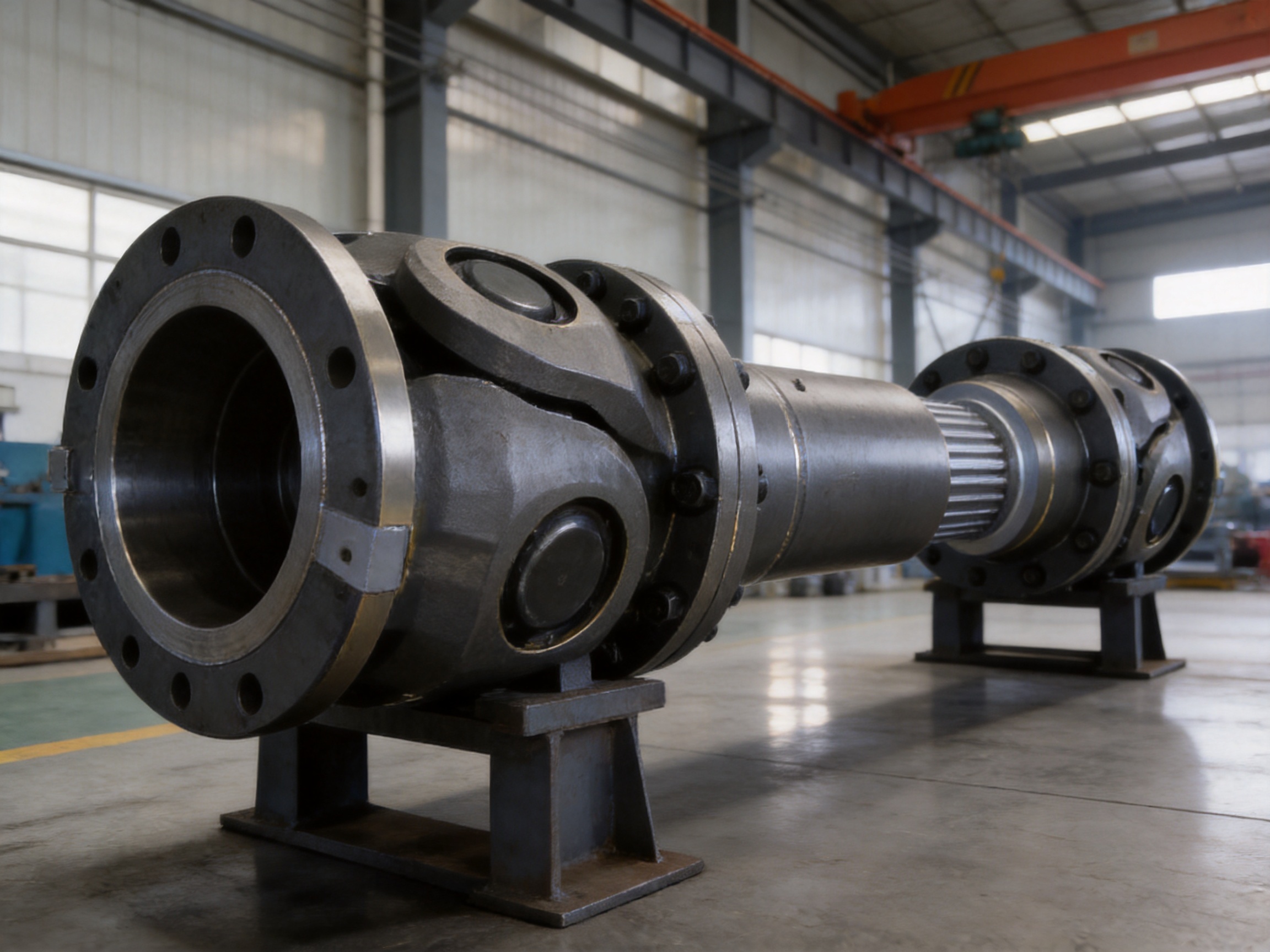
5. Application Areas
5.1 Steel and metallurgical equipment
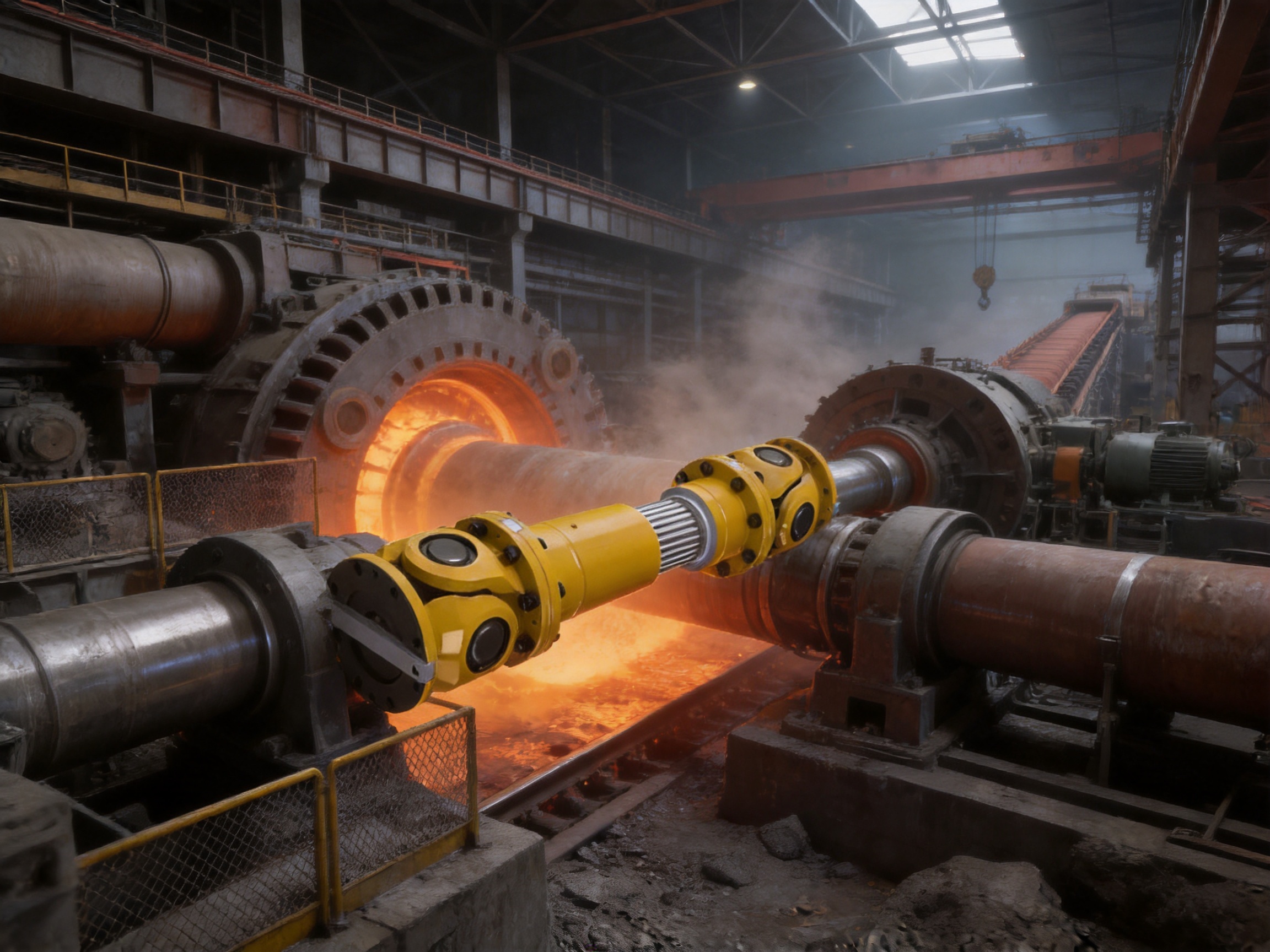
Steel production equipment often contains long drive lines, large rolls, gearboxes, and heavy rotating assemblies. The equipment may experience high torque, frequent starts and stops, thermal variation, and structural deflection. A universal coupling can accommodate angular deviations between the drive and driven components, while the telescopic flange can compensate for axial movement caused by heat and machine deformation.
Potential applications include rolling mills, steel processing lines, transfer equipment, continuous casting auxiliaries, large shears, furnace-related machinery, and other metallurgical systems. Selection should consider the motor or turbine output, gearbox ratio, roll torque, operating cycle, shock load, and expected temperature range.
5.2 Mining and crushing machinery
Mining equipment is frequently exposed to shock loads, dust, vibration, and uneven operating conditions. Crushers, mills, conveyors, reclaimers, stackers, and large material-handling machines require reliable torque transmission and may have long shafts or separated drive units.
The coupling can help accommodate misalignment generated by structural movement and foundation conditions. Its high nominal torque capacity makes it suitable for large drives, while the range of model sizes allows the selection to be matched to the load. For crushing applications, engineers should pay particular attention to transient torque, blockage conditions, start-up loads, and torsional vibration.
5.3 Power generation and energy equipment
Energy systems depend on continuous operation and controlled vibration. Large fans, pumps, auxiliary drives, hydro equipment, and other power-generation machinery may require a coupling that accommodates thermal growth between connected machines. The axial movement capability of the telescopic flange can be useful where the machine train changes dimension during warm-up or under sustained operating temperature.
For power-generation applications, coupling selection should include a detailed review of rotational speed, balance requirements, torsional characteristics, bearing loads, emergency shutdown conditions, and alignment procedures. The coupling should be integrated into the overall rotor-dynamic and maintenance plan.
5.4 Shipbuilding and marine engineering
Shipboard machinery and marine systems operate on structures that can flex under load. Propulsion-related systems, large pumps, winches, cranes, and auxiliary drives may experience changes in alignment as the vessel structure responds to loading and sea conditions.
A universal coupling can provide controlled angular compensation in a shaft line, while the telescopic function may assist with axial movement. Marine applications also require careful consideration of corrosion protection, sealing, lubrication, balance, access, and classification or project-specific requirements. The coupling should be specified together with the complete marine shafting system.
5.5 Lifting, port, and large conveying systems
Lifting equipment and port machinery often operate with variable loads and frequent acceleration and deceleration. Large conveyors, ship unloaders, stacker-reclaimers, and heavy cranes may use drive systems with long center distances and structural movement.
The SWC-BF series can be considered where the drive requires high torque and where a rigid coupling would not provide sufficient movement compensation. Engineers should evaluate braking torque, emergency stop loads, reversing duty, duty cycle, and the influence of suspended or moving loads.
6. Manufacturing Strengths and Engineering Capabilities
The manufacturer, Zhongye Heavy Industry Technology (Zhenjiang) Co., Ltd., integrates research and development, manufacturing, and sales. Its product portfolio includes universal couplings, toothed couplings, elastic sleeve column pin couplings, elastic column pin couplings, gear couplings with elastic pins, tire couplings, jaw couplings, star couplings, diaphragm couplings, drum couplings, grid couplings, Oldham couplings, flange couplings, clip-shell couplings, roller-chain couplings, safety couplings, and other transmission products.
This breadth is important because coupling selection is rarely isolated from the rest of a machine. A company experienced with multiple coupling technologies can compare rigid, elastomeric, metallic, gear, diaphragm, universal, and safety coupling concepts according to torque, speed, misalignment, environment, maintenance, and installation conditions. It can also recommend a different coupling principle when the standard configuration is not the best solution.
6.1 Dedicated production facilities
The company’s new workshop covers approximately 16,463.52 square meters. The facility includes a heavy workshop of approximately 5,500 square meters, a precision workshop of approximately 4,600 square meters, an office building and gymnasium of approximately 2,000 square meters, a dining hall of approximately 500 square meters, a warehouse of approximately 1,000 square meters, and additional areas for roads, landscaping, and parking.
The separation between heavy and precision work areas is valuable for the manufacture of large couplings. Heavy components require suitable lifting capacity, machining capability, handling systems, and assembly space. Precision components require controlled machining, measurement, finishing, and inspection. A facility organized for both requirements can support the dimensional accuracy and structural scale needed for large universal couplings.
6.2 Research and development
Large couplings require more than simple component fabrication. Their design must account for torque transmission, angular kinematics, bearing loads, fatigue, shaft alignment, expansion movement, flange strength, lubrication, balance, and maintainability. A professional research and development team can evaluate these factors during product development and customization.
The company supports non-standard design solutions in addition to standard coupling models. This capability is useful when an installation has unusual shaft dimensions, special flange interfaces, limited space, unique expansion requirements, non-standard operating angles, or special environmental conditions. Customized engineering should be based on complete technical data from the equipment owner, including power, speed, torque, shaft dimensions, angle, axial movement, duty cycle, temperature, and installation constraints.
6.3 Testing and quality control
Reliable coupling performance depends on material quality, machining accuracy, heat treatment where applicable, assembly control, dimensional inspection, balancing, surface protection, and final testing. The company states that it has advanced testing facilities and strict quality control procedures. These capabilities support the production of coupling components that must operate under high mechanical loads and long service cycles.
Quality control for a large universal coupling should include verification of critical dimensions, shaft and flange interfaces, bolt-hole positions, joint movement, bearing and lubrication conditions, runout, component fit, and overall assembly condition. Depending on the project, additional tests or inspection records may be requested by the customer.
The company’s products are described as complying with international standards and certifications such as ISO 9001. Customers should confirm the specific standards, certificates, inspection scope, and documentation required for each order and application.
7. Installation and Commissioning Considerations
7.1 Confirm the operating data
Before installation, the engineer should verify the transmitted torque, rated power, rotational speed, axis angle, axial displacement, load spectrum, start-up condition, stopping condition, and environmental temperature. The coupling should be selected according to the most demanding credible operating condition, not only the average running load.
Where the drive experiences impact or fluctuating loads, a service factor should be applied according to the machinery duty and engineering standard. If there is a risk of blockage, sudden braking, reversing, or resonance, transient torque should be evaluated. The nominal torque rating alone may not describe every condition that the coupling must survive.
7.2 Verify shaft and flange dimensions
The shaft diameter, keyway or other connection method, flange diameter, bolt-hole circle, bolt size, pilot dimensions, and available axial space should be compared with the coupling drawings and technical data. The D1 and D2 dimensions include specified tolerances, and these interfaces should be prepared accurately to ensure proper fit.
Incorrect shaft preparation can create eccentricity, excessive runout, or local stress concentration. Bolt holes should not be enlarged or modified without written engineering approval. The flange faces should be clean, flat, and free from burrs, scale, paint buildup, or foreign material that could prevent full contact.
7.3 Alignment and movement allowance
The coupling compensates for defined angular and axial movement, but it should not be used to correct poor installation. Initial shaft alignment should be performed carefully using appropriate measurement equipment. The coupling should be installed so that the expected expansion and contraction can occur without obstruction.
The specified expansion and contraction quantity is a design allowance, not a substitute for calculating the actual thermal movement. The machine train should be evaluated from cold to hot operating conditions. Supports, bearings, guards, and neighboring equipment should be checked to ensure that they do not restrict telescopic movement.
7.4 Fastener tightening and inspection
Flange bolts should be installed according to the approved assembly procedure and tightened in a controlled sequence. Correct bolt grade, lubrication condition, tightening method, and torque value are essential. Uneven tightening can distort the flange or create non-uniform load distribution.
After initial commissioning, the coupling should be inspected for abnormal noise, vibration, temperature rise, leakage, looseness, or visible movement outside the intended range. A follow-up inspection after the first operating period can identify installation issues before they develop into serious damage.
8. Maintenance and Service Life
Maintenance requirements depend on the operating environment, speed, load, angle, lubrication system, and coupling configuration. A maintenance plan should identify inspection intervals, lubrication requirements, bolt checks, wear monitoring, alignment verification, and replacement criteria.
In dusty mining environments, contamination control is particularly important. In hot metallurgical applications, lubricant selection and temperature monitoring require special attention. In marine environments, corrosion protection and sealing should be inspected regularly. In high-cycle applications, fatigue-related inspection should be scheduled according to operating hours and load history.
Operators should monitor vibration trends rather than relying only on visual inspection. An increase in vibration may indicate misalignment, worn bearings, imbalance, loose fasteners, shaft problems, insufficient lubrication, or a change in operating conditions. Early detection can reduce the risk of secondary damage to the gearbox, motor, bearings, and connected machinery.
Replacement parts should be genuine or approved equivalents with the correct dimensions, material properties, and performance characteristics. Mixing components from different designs without engineering confirmation may change the coupling’s balance, load distribution, or movement behavior.
9. Selection Guide
Selecting the correct SWC-BF model requires a structured evaluation. The first step is to calculate the operating torque. For a known power and speed, the torque can be determined using the appropriate engineering relationship, with unit conversion handled carefully. The design torque should then include the applicable service factor and transient conditions.
The second step is to determine the axis angle under both cold and operating conditions. The coupling must be rated for the actual angle, and the 10° or 15° data should be used where those conditions apply. If the angle varies, the worst credible angle should be considered.
The third step is to calculate the required axial movement. This may include thermal expansion of shafts, machine housings, supporting structures, and foundation elements. The selected model must provide adequate expansion and contraction capacity while retaining a suitable operating margin.
The fourth step is to verify the physical dimensions. This includes shaft diameter, flange dimensions, minimum length, overall length, bolt-hole pattern, radial clearance, axial clearance, guard dimensions, and installation access.
The fifth step is to assess bearing life, lubrication, speed, balance, and environmental conditions. The bearing life factor supplied in the technical data can support preliminary evaluation, but final bearing-life calculations should include the actual loads and duty cycle.
| Selection Item | Information Required | Why It Matters |
|---|---|---|
| Torque | Continuous, peak, starting, braking, and shock torque | Determines the required transmission capacity |
| Rotational speed | Normal and maximum speed | Influences balance, bearing load, and lubrication |
| Axis angle | Cold, operating, and maximum angular deviation | Changes torque rating and bearing conditions |
| Axial movement | Thermal, structural, and installation displacement | Determines required telescopic allowance |
| Interface dimensions | Shafts, flanges, bolt pattern, pilots, and available space | Ensures physical compatibility |
| Environment | Temperature, dust, water, corrosion, and vibration | Guides sealing, lubrication, and protection measures |
| Maintenance plan | Inspection access, lubrication schedule, and spare parts | Supports long-term reliability |
10. Why the SWC-BF Series Is a Competitive Choice
The competitive value of the SWC-BF series comes from the combination of features rather than from a single specification. It provides a standard product platform for very large torque transmission, but it also accommodates angular and axial movement. This combination can reduce the need to choose between a rigid coupling with insufficient movement capability and a lighter flexible coupling with insufficient torque capacity.
The range of eleven model sizes allows equipment designers to select a closer match to the required load. The standardization of the product family can simplify procurement, plant-wide maintenance, and replacement planning. The three listed operating-angle conditions provide useful selection data for systems with different shaft arrangements.
The product is also supported by a manufacturer with experience across many coupling categories. This means that the customer can obtain technical discussion for standard products, customized couplings, non-standard flange connections, and complete transmission solutions. Such engineering support can be especially valuable for large projects where coupling performance affects the reliability of the entire machine train.
Another advantage is the combination of manufacturing scale and precision capability. A large universal coupling must be structurally strong, but it must also maintain appropriate dimensional accuracy and assembly quality. The manufacturer’s heavy workshop and precision workshop provide a foundation for producing components that satisfy both requirements.
11. Customization and Technical Support
Although the SWC-BF series is offered as a standard product family, heavy machinery projects frequently require adaptation. Possible customization areas may include shaft interfaces, flange dimensions, bolt-hole patterns, overall length, telescopic movement, protective arrangements, lubrication provisions, materials, coatings, and installation accessories.
Customization should begin with a complete technical questionnaire. The customer should provide the machine type, motor or engine power, speed, continuous torque, peak torque, duty cycle, shaft diameters, key or spline details, angular deviation, axial movement, ambient conditions, expected service life, installation orientation, and available space.
Drawings should be reviewed before production to confirm all critical interfaces. For large assemblies, transportation weight, lifting points, packaging, storage, and site assembly should also be considered. Clear communication at the design stage can prevent delays during installation and reduce the risk of modifications in the field.
The manufacturer provides pre-sale technical support, non-standard design solutions, production coordination, and after-sale service support. These services are particularly relevant to steel mills, mining projects, energy plants, ports, and other facilities in which the coupling is integrated into a larger engineered system.
12. Frequently Asked Questions
What is the primary function of the SWC-BF coupling?
The primary function is to transmit very high torque between connected shafts while compensating for controlled angular displacement and axial expansion or contraction. It is intended for large industrial machinery and demanding shaft-line applications.
What does “telescopic” mean in this coupling?
Telescopic means that the coupling can accommodate axial movement by allowing expansion and contraction along the shaft-line direction. The available movement listed for the series is 250 mm, 300 mm, or 350 mm depending on the model.
What is the largest available model?
The largest listed model is the SWC1320BF. It has a 1,320 mm turning diameter, a nominal torque of 16,000 kN·m at 5°, and a fatigue torque of 9,600 kN·m at 5°. Its listed expansion and contraction quantity is 350 mm.
Can the coupling operate at 15°?
Yes. The technical data includes operating conditions of 5°, 10°, and 15°. However, torque and fatigue torque ratings decrease as the operating angle increases, so the model must be selected using the actual working angle.
Is this coupling suitable for steel mill equipment?
Yes. Its high torque capacity, angular compensation, and axial movement capability make it suitable for many steel and metallurgical applications. The final selection must consider the specific machine load, speed, shock conditions, thermal movement, and installation dimensions.
Is it suitable for mining crushers?
It can be considered for large crushers and related mining machinery. Crusher applications require careful evaluation of impact torque, blocked-rotor conditions, start-up loads, vibration, dust protection, and maintenance access.
Does the coupling eliminate the need for alignment?
No. It compensates for defined displacement, but proper alignment remains essential. Incorrect installation can cause excessive bearing loads, vibration, wear, and reduced service life.
How should the model be selected?
The model should be selected using torque, speed, axis angle, axial movement, dimensions, load spectrum, environment, bearing-life requirements, and maintenance conditions. The selection should be checked against both continuous and transient operating loads.
Can a non-standard version be manufactured?
Yes. The manufacturer undertakes the design and manufacture of non-standard couplings. Customers should provide complete technical information so that the shaft interfaces, flange geometry, length, movement allowance, and operating conditions can be reviewed before production.
What information is needed for a quotation?
Useful information includes equipment type, power, speed, torque, shaft diameter, shaft connection, angular deviation, axial movement, operating temperature, environmental conditions, installation space, quantity, and any required standards or inspection documentation.
What industries does the manufacturer serve?
The manufacturer’s products are used in metallurgical equipment, mining equipment, water equipment, lifting equipment, paper equipment, port equipment, energy systems, shipbuilding, and other industrial fields.
What support is available after purchase?
Available support includes technical assistance, product documentation, installation guidance, non-standard design support, spare-parts coordination, and after-sale service. The exact scope should be confirmed for each project.
13. Conclusion
The SWC-BF large-size standard telescopic flange universal coupling is engineered for heavy-duty power transmission where high torque, angular displacement, and axial movement must be managed in one mechanical assembly. With turning diameters from 620 mm to 1,320 mm, nominal torque ratings up to 16,000 kN·m, fatigue torque ratings up to 9,600 kN·m, and operating angles up to 15°, it addresses the requirements of large industrial drive systems.
Its principal advantages include a broad standardized size range, a substantial telescopic expansion and contraction capability, controlled universal-joint movement, large flange interfaces, and suitability for severe industrial environments. These features make it a strong alternative to rigid couplings where axial movement and angular deviation are present, and to smaller flexible couplings where torque and structural demands are exceptionally high.
The effectiveness of any coupling depends on correct engineering, installation, lubrication, inspection, and maintenance. Selection should be based on actual torque, speed, angle, movement, dimensions, environment, and duty cycle. When these factors are properly evaluated, the SWC-BF series can support reliable operation in steel plants, mines, energy facilities, shipyards, ports, and other heavy machinery installations.
Backed by research and development, heavy and precision manufacturing facilities, quality control, testing capabilities, standard product expertise, and customization support, Zhongye Heavy Industry Technology (Zhenjiang) Co., Ltd. provides a practical source for large universal couplings and related transmission solutions. Its technical capability across multiple coupling technologies also allows customers to seek a solution that is matched to the complete machine system rather than to a single isolated component.
References
1. Product technical data: BF Type Large-Size Standard Telescopic Flange Universal Coupling Basic Parameters and Main Dimensions.
2. Manufacturer product information for the SWC-BF large-size standard telescopic flange universal coupling.
3. General engineering principles for universal joint couplings, shaft alignment, torque transmission, and axial movement compensation.
4. Industrial coupling selection practices for metallurgical, mining, power-generation, port, lifting, and shipbuilding equipment.
5. General maintenance principles for high-torque mechanical couplings, bearings, flange connections, lubrication systems, and rotating machinery.
6. Quality management and manufacturing information supplied for Zhongye Heavy Industry Technology (Zhenjiang) Co., Ltd.
Product: SWC-BF large size standard expansion flange universal coupling

- Quick Links
- About
- Products
- Our Service
- News & Events
- Contact
- Products Series
- Flexible Couplings with Non-Elastic Elements
- Flexible Couplings with Metal Elastic Elements
- Flexible Couplings with Non-Metallic Elastic Elements
- Safety Coupling
- Rigid Coupling
- Contact Us
- Tel : +86 511 8572 3800 +86 511 8572 3900
- Mobile : +86 15106109009
- Email : sales@couplingzy.com
- Add:No.1 Zhongye Yingbin Avenue, Gaozi Street, Dantu Economic Development Zone, Zhenjiang City, Jiangsu Province, China.


