:+86 15106109009
:sales@couplingzy.com


 English
 русский
 Español
 عربى
 Português
 Deutsch
 Türk
 Indonesia


GAP Drum Gear Coupling with Brake Disc: Advanced Power Transmission for Heavy-Duty Industrial Systems
Content
- 1 1. Product Overview and Operating Purpose
- 2 2. Core Design and Structural Features
- 3 3. Performance Advantages Compared with Conventional Alternatives
- 4 4. Technical Specification Range
- 5 5. Brake Torque and Safety Considerations
- 6 6. Manufacturing Technology and Quality Strengths
- 7 7. Industrial Applications
- 8 8. Selection and Engineering Procedure
- 9 9. Installation and Maintenance Recommendations
- 10 10. Why Choose a Specialized Coupling Manufacturer
- 11 11. Frequently Asked Questions
- 11.1 Q1: What type of coupling is the GAP model?
- 11.2 Q2: What is the nominal torque range?
- 11.3 Q3: Can the coupling rotate in both directions?
- 11.4 Q4: What is the maximum allowable braking torque?
- 11.5 Q5: Why is the brake disc mounted directly on the half coupling?
- 11.6 Q6: What does the “e” dimension mean?
- 11.7 Q7: What bore configurations are available?
- 11.8 Q8: What brake disc diameters are available?
- 11.9 Q9: Is the GAP coupling suitable for high-speed machinery?
- 11.10 Q10: Does the coupling require lubrication?
- 11.11 Q11: Can the product be customized?
- 11.12 Q12: Which industries commonly use this coupling?
- 11.13 Q13: Does the coupling eliminate the need for shaft alignment?
- 11.14 Q14: How should the coupling be selected?
- 12 12. Conclusion
- 13 References
- 14 Product: GAP Drum gear coupling with brake disc (Q/YG 12008X-2018)
Reliable torque transmission, controlled braking, and compensation for shaft misalignment are essential requirements in modern heavy industrial machinery. Lifting equipment, metallurgical machinery, mining systems, port equipment, conveyors, paper machines, and water-treatment installations frequently operate under high loads, repeated starting and stopping cycles, vibration, and demanding environmental conditions. In these applications, the coupling is not merely a connection between two shafts. It is a precision transmission component that influences system safety, service life, maintenance requirements, and operating efficiency.
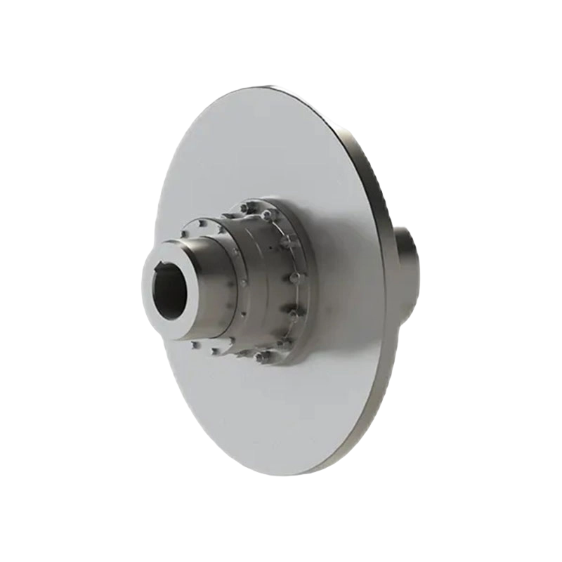
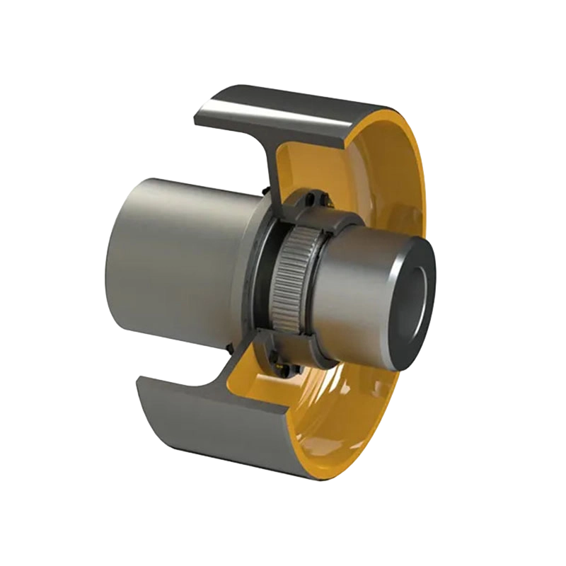
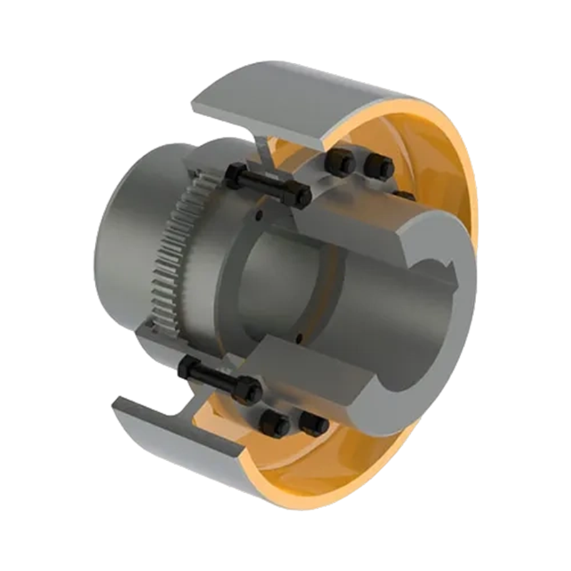
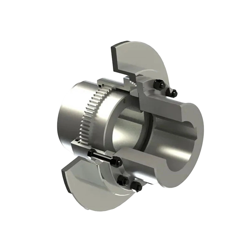
The GAP drum gear coupling with brake disc, manufactured according to Q/YG 12008X-2018, is designed for these demanding conditions. It combines the high torque capacity of a gear coupling with an integrated braking interface. Its crowned gear-tooth structure compensates for installation and operating misalignment, while its wide internal gear sleeve provides enhanced axial displacement compensation. The brake disc is mounted directly on the half coupling, creating a load-distribution arrangement intended to improve tooth engagement and reduce harmful effects during braking.
The GAP series includes models from GAP1 through GAP14. Nominal torque ratings range from 630 N·m to 112,000 N·m, while standard brake disc diameters extend from 315 mm to 1,000 mm. Depending on the model, allowable speed reaches up to 4,000 r/min, and available bore configurations support a broad range of shaft arrangements. This combination of torque capacity, speed capability, braking integration, and misalignment compensation makes the series suitable for both standard industrial machinery and customized heavy-duty transmission systems.
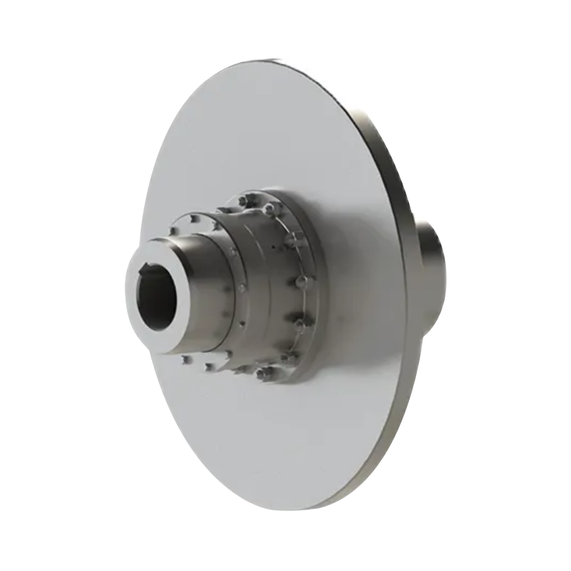
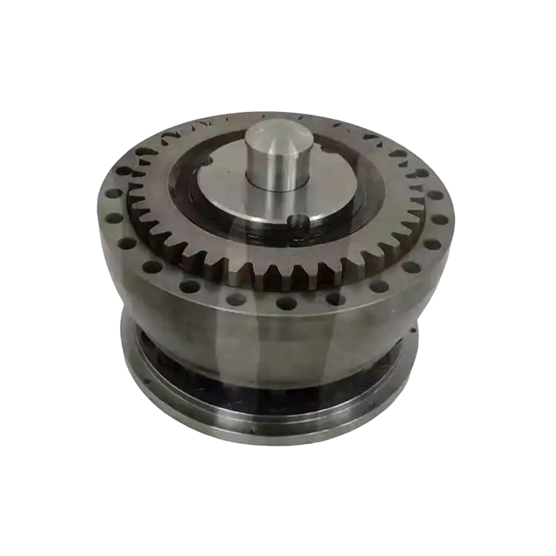
GAP Drum gear coupling with brake disc (Q/YG 12008X-2018)
1. Product Overview and Operating Purpose
A drum gear coupling is a flexible coupling with non-elastic elements. Instead of using rubber, polymer blocks, or metallic springs as the primary flexible element, it uses the controlled clearance and crowned geometry of gear teeth to accommodate angular, radial, and axial shaft displacement. Torque is transmitted through the engagement of external gear teeth on the half coupling and internal gear teeth in the sleeve.
The GAP design adds a brake disc to this transmission arrangement. The integrated disc provides a mounting surface for a disc brake system and allows the coupling and brake assembly to function as a coordinated unit. This is particularly useful where the driven machine must be stopped quickly, positioned accurately, or held securely after deceleration.
In a typical installation, the GAP coupling may be used together with GBZ and GAZ couplings. The intermediate shaft is connected through the external gear sleeve end, while the brake disc is fixed directly to the half coupling. This arrangement transfers the brake disc mass and braking vibration into the half coupling rather than allowing these loads to act excessively on the gear mesh or intermediate shaft connection.
The coupling is bidirectional. It can transmit torque during clockwise and counterclockwise rotation, making it suitable for reversing drives, positioning systems, lifting mechanisms, and machines that experience frequent changes in direction.
1.1 Main functional objectives
The design addresses several practical requirements at the same time:
First, it transmits high torque from one shaft to another while maintaining a relatively compact mechanical connection.
Second, it compensates for shaft misalignment caused by manufacturing tolerances, foundation movement, thermal expansion, bearing displacement, and assembly conditions.
Third, it provides a dedicated interface for a brake disc, reducing the need for a separate disc-support structure.
Fourth, it supports repeated braking and reversing operations without relying on an elastic insert that may fatigue, harden, or deteriorate with age.
Fifth, it incorporates a maintenance clearance dimension identified as “e,” allowing seals to be replaced without completely dismantling the transmission system.
2. Core Design and Structural Features
2.1 Wide internal gear sleeve
One of the most important structural features of the GAP coupling is its wider internal gear sleeve. Compared with conventional configurations, the wider sleeve provides a larger effective tooth-engagement area and improved axial movement capability. This allows the coupling to accommodate greater axial displacement while maintaining functional contact between the crowned gear teeth.
Axial displacement can occur when shafts move because of thermal expansion, bearing float, structural deflection, or changes in machine loading. If a coupling cannot accommodate this movement, excessive axial force may be transferred to the bearings and connected equipment. The GAP structure is intended to reduce this risk by providing additional internal space and axial compensation capacity.
The wider sleeve also contributes to more stable engagement when the connected shafts are not perfectly aligned. Proper tooth engagement is essential because uneven contact can increase local stress, noise, wear, and temperature. By supporting a broader operating envelope, the sleeve geometry helps the coupling maintain reliable torque transmission under complex operating conditions.
2.2 Crowned gear teeth
The gear teeth are crowned rather than completely flat across their tooth width. This geometry allows the teeth to maintain contact when the connected shafts experience angular or radial misalignment. The crown reduces the tendency for tooth edges to carry excessive load and helps distribute torque more evenly across the working tooth surface.
Crowned teeth are especially valuable in heavy machinery because alignment cannot always remain ideal during operation. A large lifting mechanism may deflect as its load changes. A rolling mill may experience shock and frame movement. A conveyor may be installed over a long distance with multiple structural supports. In these conditions, a rigid, non-compensating connection would transmit excessive forces into the shafts and bearings.
Gear-tooth compensation does not eliminate the need for alignment. Installation should still follow the specified shaft centerline, axial clearance, and mounting requirements. However, the crowned tooth profile provides a practical operating margin and helps the coupling tolerate unavoidable displacement more effectively than a rigid coupling.
2.3 Direct brake disc mounting
The brake disc is mounted directly on the half coupling. This is a major difference from arrangements in which a brake disc is mounted on an independent extension, a long intermediate shaft, or a separate support bracket.
Direct mounting allows the half coupling to absorb the weight of the disc and the vibration generated during braking. The braking torque is therefore introduced into a component designed to transmit torque and withstand mechanical loading. This reduces the likelihood that disc-related loads will produce excessive movement in the gear sleeve or intermediate shaft connection.
When the disc is mounted directly on the half coupling, the overall braking structure can also be more compact. A shorter load path may help reduce overhung loading and simplify the connection between the brake, coupling, and driven machine. The exact arrangement must be confirmed against the brake manufacturer’s requirements, including disc diameter, disc thickness, friction surface specification, braking torque, thermal capacity, and allowable speed.
2.4 Bidirectional rotation
The GAP coupling can operate in both directions of rotation. This makes it appropriate for reversing drives and equipment that must frequently alternate between forward and reverse movement.
Bidirectional operation is particularly important in lifting and positioning equipment. Hoisting mechanisms may raise and lower a load, while traveling mechanisms may move a machine forward and backward. In metallurgical machinery, reversing tables and transfer systems may apply alternating torque to the drive train. The coupling must maintain stable gear-tooth engagement in either direction without depending on a one-way mechanical feature.
Although the coupling supports both rotation directions, the complete system must still be evaluated for torsional shock. Motor acceleration, brake release timing, emergency stopping, load inertia, and control-system response can all influence peak torque. The coupling should be selected using the highest expected operating and transient loads rather than nominal motor torque alone.
3. Performance Advantages Compared with Conventional Alternatives
3.1 Higher torque capacity than many elastic couplings
The GAP series covers nominal torque ratings from 630 N·m to 112,000 N·m. This broad range allows one product family to serve applications ranging from relatively compact high-speed machinery to very large, slow-speed heavy-duty equipment.
Many elastic couplings are highly effective in applications requiring vibration damping and moderate torque transmission. However, as torque, bore size, and braking requirements increase, elastic elements may require larger dimensions or special materials. The GAP coupling instead transmits torque through gear teeth and can therefore provide a robust solution for large power systems where compactness and high load capacity are important.
The series includes fourteen model sizes. This provides more opportunities to select a coupling close to the actual system requirement rather than using an unnecessarily oversized product. Appropriate sizing can help control cost, installation space, rotating mass, and moment of inertia.
3.2 Better suitability for integrated braking
A conventional flexible coupling and a separately mounted brake disc may require additional hubs, brackets, shaft extensions, and supporting components. These parts can increase assembly complexity and create additional sources of alignment error.
The GAP design integrates the brake disc with the coupling half. This arrangement simplifies the mechanical relationship between torque transmission and braking. It can also reduce the amount of independent supporting structure required around the shaft line.
The direct mounting arrangement is particularly beneficial when the machine must stop accurately and repeatedly. The brake disc remains mechanically associated with the coupling that transmits drive torque, helping the braking force enter the drive system through a controlled load path.
3.3 Improved compensation for axial displacement
Axial movement is often overlooked during coupling selection. A machine may experience axial growth as its temperature rises, or shafts may move because of bearing tolerances and structural deflection. If the coupling is unable to accommodate this movement, it can impose unintended thrust loads on the connected equipment.
The wider internal gear sleeve of the GAP series is designed to provide superior axial displacement compensation compared with more conventional internal sleeve arrangements. This feature is useful in long-shaft systems, high-temperature equipment, and machinery where the relative shaft position changes during operation.
3.4 Lower risk of edge loading
Edge loading occurs when misaligned gear teeth make concentrated contact near their edges. It can result in high local stress, tooth wear, pitting, heat generation, and abnormal noise. The crowned gear profile helps reduce this problem by maintaining more favorable tooth contact when the shafts are not perfectly collinear.
As with any gear coupling, lubrication and alignment remain essential. The crowned profile improves tolerance to operating displacement, but it cannot compensate for severe installation errors or insufficient lubrication. Correct installation and planned inspection are necessary to realize the full benefit of the design.
3.5 High-speed capability for smaller models
The GAP1 model has an allowable speed of up to 4,000 r/min. This demonstrates that the product family is not limited to slow-speed heavy machinery. Smaller models can support relatively high rotational speeds while maintaining balanced operation and low vibration when correctly installed.
Allowable speed depends on model size, bore arrangement, balance condition, brake disc configuration, and operating environment. A complete selection should consider the rotating mass of the brake disc, the balance quality of all connected components, and the dynamic behavior of the entire shaft train.
3.6 Maintenance-friendly seal replacement
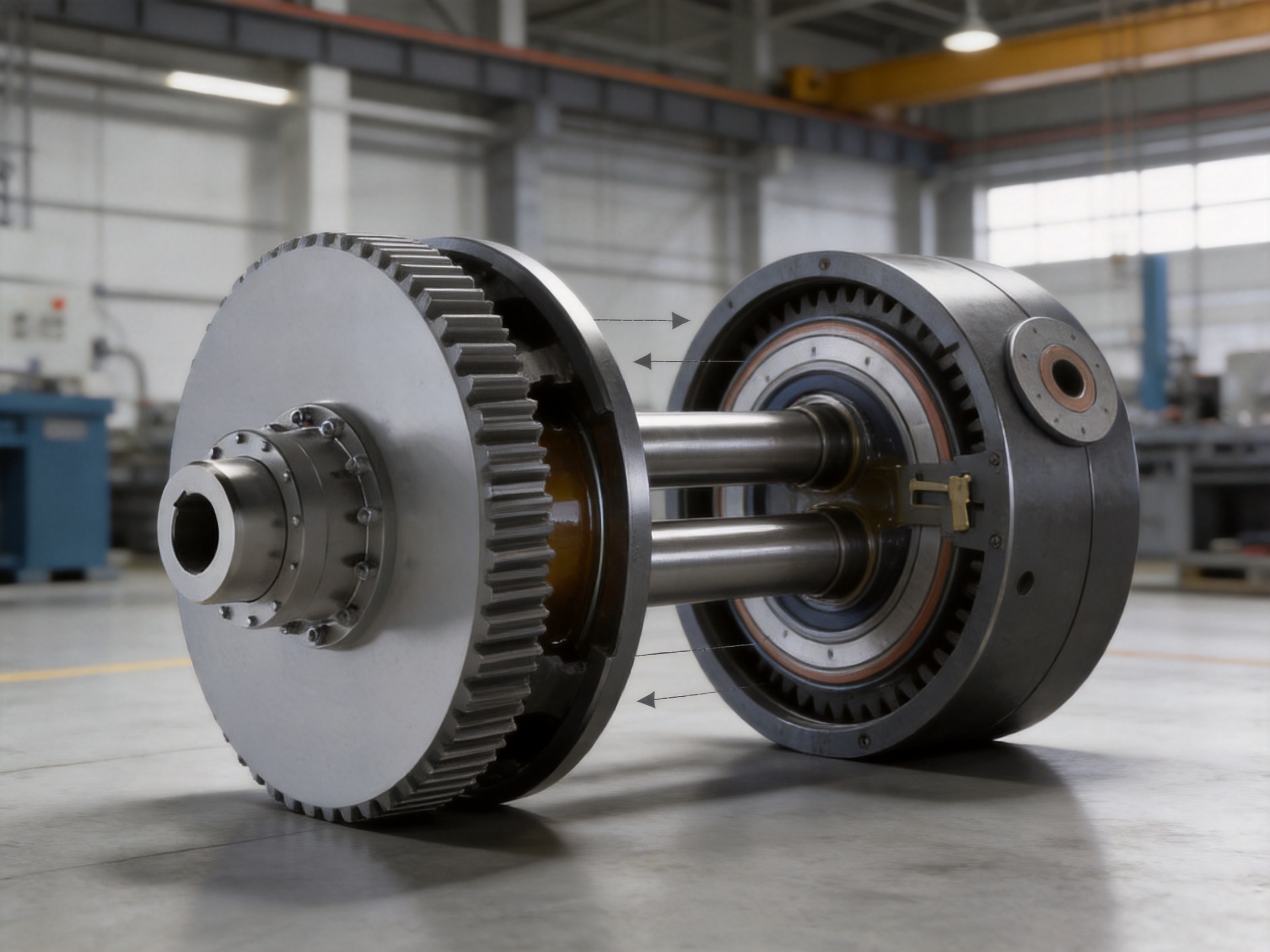
The dimension identified as “e” is reserved for seal replacement. This clearance enables maintenance personnel to access and replace seals without completely dismantling the coupling and connected machinery.
This feature can reduce maintenance time and lower the risk of damage to adjacent components during service. It is especially useful for equipment installed in locations where access is limited or where disassembly would require lifting large components. Shorter maintenance operations can also improve equipment availability and reduce production interruptions.
4. Technical Specification Range
The GAP series is available in models GAP1 through GAP14. The following summary provides representative nominal torque, allowable speed, and brake disc data. Final selection must be based on the complete dimensional drawing, shaft details, operating conditions, and brake requirements.
| Model | Nominal Torque | Allowable Speed | Typical Brake Disc Diameter Range | Approximate Maximum Bore Indication |
|---|---|---|---|---|
| GAP1 | 630 N·m | 4,000 r/min | 315 mm | Up to approximately 60 mm |
| GAP2 | 1,120 N·m | Application dependent | 315 mm | Up to approximately 84 mm |
| GAP3 | 2,240 N·m | 3,550 r/min | 355 mm | Up to approximately 107 mm |
| GAP4 | 3,550 N·m | 2,500 r/min | 400–500 mm | Up to approximately 107 mm |
| GAP5 | 5,000 N·m | 2,500 r/min | 400–500 mm | Up to approximately 107 mm |
| GAP6 | 7,100 N·m | 2,000 r/min | 450–630 mm | Up to approximately 132 mm |
| GAP7 | 10,000 N·m | 1,700 r/min | 450–630 mm | Up to approximately 132 mm |
| GAP8 | 14,000 N·m | 1,700 r/min | 500–710 mm | Up to approximately 167 mm |
| GAP9 | 18,000 N·m | 1,600 r/min | 560–800 mm | Up to approximately 167 mm |
| GAP10 | 31,500 N·m | 1,600 r/min | 630–800 mm | Up to approximately 202 mm |
| GAP11 | 40,000 N·m | 1,400 r/min | 710–900 mm | Up to approximately 242 mm |
| GAP12 | 56,000 N·m | 1,400 r/min | 710–900 mm | Up to approximately 242 mm |
| GAP13 | 80,000 N·m | 1,400 r/min | 800–900 mm | Up to approximately 282 mm |
| GAP14 | 112,000 N·m | 1,200 r/min | 900–1,000 mm | Up to approximately 282 mm |
The source dimensions identify several bore combinations, including Y–Y, J1–J1, Z–Z, Z1–J1, and mixed arrangements such as Y–J1. These options help engineers match the coupling to different shaft-end geometries and installation conditions.
The published data also include shaft hole diameters, shaft hole lengths, overall diameters, gear dimensions, installation dimensions, grease quantities, mass, and moment of inertia. These parameters are important when evaluating the coupling as part of a complete rotating system. Mass and moment of inertia influence motor acceleration, brake sizing, dynamic response, and energy dissipation during stopping.
5. Brake Torque and Safety Considerations
5.1 Maximum braking torque
The design specification states that the maximum braking torque, Tm, must not exceed twice the nominal coupling torque, Tn:
Tm ≤ 2Tn
This limitation provides an important safety margin. A brake can generate a high transient torque during emergency stopping, abrupt deceleration, or unexpected load movement. If that torque exceeds the capacity of the coupling, gear teeth, shafts, keys, or connected equipment, mechanical damage may occur.
Brake selection must therefore be coordinated with coupling selection. The brake’s maximum torque, not only its normal operating torque, should be compared with the permissible coupling value. The effects of motor torque, load inertia, gearbox ratio, braking time, and emergency-stop behavior should also be included in the calculation.
5.2 Disc and brake compatibility
The brake disc diameter must be compatible with the selected brake caliper or disc brake assembly. Important interface factors include disc diameter, usable friction radius, disc thickness, mounting arrangement, axial runout, surface finish, and allowable rotational speed.
Brake heat must also be evaluated. During repeated stopping, the disc absorbs kinetic energy and converts it into heat. The coupling may remain mechanically sound while the brake system becomes thermally overloaded if the duty cycle is not correctly calculated. Engineers should consider stopping frequency, load inertia, speed before braking, ambient temperature, cooling conditions, and required holding time.
5.3 Emergency stopping
Emergency stopping can generate substantially higher torsional shock than normal controlled stopping. The control system, motor, gearbox, shaft, coupling, and brake should be evaluated as one torsional system. Where necessary, a dynamic calculation should be completed to determine peak torque and torsional oscillation.
The GAP coupling’s gear structure is intended for robust power transmission, but it should not be treated as a substitute for a correctly designed braking and safety system. Mechanical guards, brake monitoring, overload protection, torque limitation, and emergency procedures remain necessary.
6. Manufacturing Technology and Quality Strengths
Zhongye Heavy Industry Technology (Zhenjiang) Co., Ltd. integrates research and development, manufacturing, and sales. Its product range includes gear couplings, drum couplings, diaphragm couplings, grid couplings, jaw couplings, tire couplings, universal couplings, flange couplings, safety couplings, and other standard and customized transmission products.
The company operates a new workshop with a total area of approximately 16,463.52 square meters. The facility includes a heavy workshop of about 5,500 square meters, a precision workshop of about 4,600 square meters, an office building and gymnasium, a dining facility, a warehouse, and supporting roads, green areas, and parking areas. This organization provides space for heavy fabrication, precision machining, assembly, storage, inspection, and technical management.
6.1 Engineering and product development
Coupling design begins with a clear understanding of the operating conditions. Engineers must consider nominal torque, peak torque, speed, bore dimensions, shaft extension, axial movement, radial and angular misalignment, braking duty, ambient conditions, lubrication, installation space, and maintenance access.
The company’s experience across multiple coupling categories allows it to compare different transmission principles when developing a solution. A gear coupling may be recommended where high torque and misalignment compensation are the priority. A diaphragm coupling may be more appropriate where torsional rigidity and clean operation are critical. A safety coupling may be selected where overload release is required. This broad technical background supports more appropriate product selection.
6.2 Heavy-duty machining capability
Large gear couplings require stable machining processes. The gear sleeve, half coupling, flange surfaces, shaft bores, keyways, and brake-disc mounting features must be produced within controlled dimensional tolerances. Heavy components also require appropriate handling, fixturing, and machining stability to prevent deformation or dimensional drift.
A heavy workshop allows large coupling components to be processed without the space constraints associated with small general-purpose machine shops. A dedicated precision workshop supports finishing operations and inspection of critical features. Together, these capabilities help create a controlled path from raw material preparation to final assembly.
6.3 Gear-tooth manufacturing
The performance of a drum gear coupling depends strongly on tooth geometry. Tooth profile, crown, pitch accuracy, surface condition, tooth flank finish, and concentricity influence load distribution and service life.
Manufacturing should maintain consistent gear geometry across the full circumference of the sleeve and half coupling. The crowned profile must be produced accurately so that the coupling can compensate for angular displacement without creating excessive local contact. Inspection of gear dimensions and tooth contact is therefore an essential part of quality control.
6.4 Bore and keyway accuracy
The shaft bore connects the coupling to the drive and driven shafts. Incorrect bore dimensions, excessive clearance, poor concentricity, or inaccurate keyways can lead to vibration, fretting, uneven load distribution, and premature wear.
Different bore configurations, including Y, J1, and Z arrangements, allow the coupling to be adapted to different shaft standards and installation requirements. During production, the selected bore type must be matched precisely to the approved drawing and customer shaft data.
6.5 Brake-disc mounting accuracy
Because the brake disc rotates with the coupling, its mounting surface must be stable and accurately aligned. Excessive axial runout can cause brake vibration, uneven pad wear, noise, and inconsistent stopping performance. Excessive radial runout can also affect brake operation and dynamic balance.
The brake-disc mounting structure should therefore be inspected for flatness, concentricity, bolt-hole position, and surface condition. These checks complement the gear and bore inspections and help ensure that the coupling performs as a combined transmission and braking component.
6.6 Inspection and testing
Quality control for a high-capacity coupling should include material verification, dimensional inspection, gear-tooth examination, bore and keyway checking, visual inspection, balance evaluation where required, and assembly verification. Depending on the project, additional non-destructive testing or load-related verification may be specified.
Inspection records provide traceability from production to delivery. This is particularly important for heavy machinery projects where the coupling may be installed in a critical production line or lifting system. Consistent documentation also supports replacement-part identification and future maintenance.
6.7 Custom manufacturing
Not every machine can use a standard coupling without modification. Customers may require special bore sizes, unusual shaft lengths, non-standard brake disc dimensions, modified flange arrangements, special materials, additional corrosion protection, or altered installation clearances.
The company undertakes non-standard coupling design and manufacture. Customized solutions can be developed from equipment drawings, shaft data, load calculations, existing coupling dimensions, and site requirements. The design process should verify the complete load path and ensure that any modification does not reduce tooth capacity, balance quality, seal performance, or maintenance access.
7. Industrial Applications
7.1 Lifting and hoisting machinery
Lifting equipment requires controlled acceleration, reliable stopping, and accurate positioning. A failure in the power transmission or braking system can result in load movement, equipment damage, or serious safety consequences.
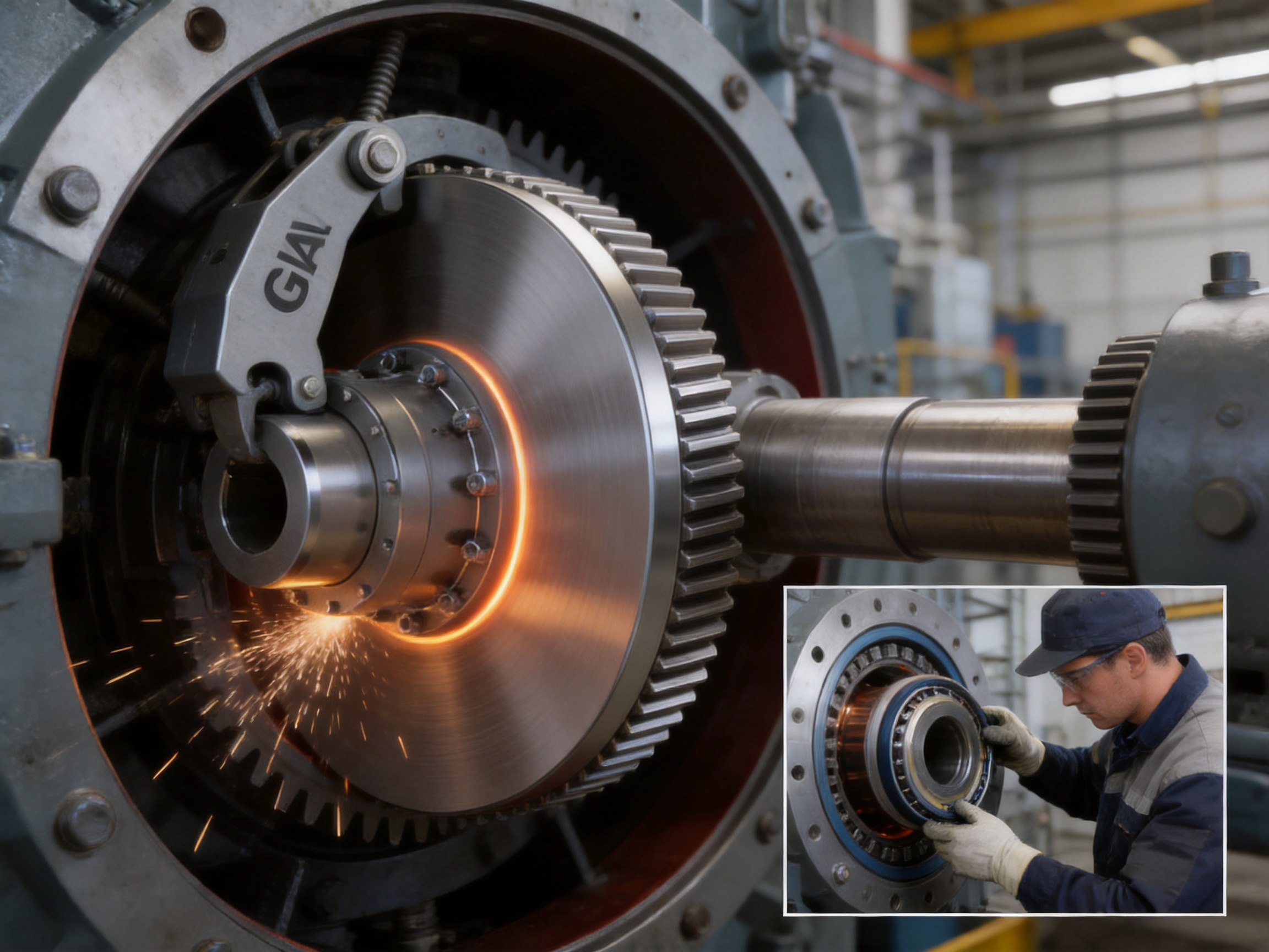
The GAP coupling supports these systems by combining torque transmission with a brake-disc mounting arrangement. It can be used in hoisting drives, traveling mechanisms, winches, transfer devices, and other machinery where the load must start and stop repeatedly.
For lifting applications, engineers should pay particular attention to brake torque, static holding requirements, emergency stopping, shock loading, load spectrum, and the effect of suspended mass. The coupling must be selected for the highest expected transient conditions, not simply the average lifting torque.
7.2 Port and marine terminal equipment
Port machinery often operates outdoors under variable weather conditions, high duty cycles, and heavy impact loads. Ship loaders, unloaders, cranes, transfer systems, and conveyor drives require robust components that can tolerate vibration and repeated braking.
The GAP coupling’s broad torque range and integrated brake disc make it suitable for drive systems where space, braking coordination, and high load capacity are important. Protective coatings, sealing, lubrication, and corrosion-control measures should be specified according to the local environment.
7.3 Metallurgical equipment
Steel mills and other metallurgical plants expose machinery to heat, dust, shock, and frequent load changes. Drives may be connected to rollers, transfer tables, shears, coilers, feeders, or heavy conveyors.
The crowned gear-tooth structure helps accommodate shaft displacement caused by frame deflection and thermal effects. The high torque capacity of the larger GAP models also supports heavy drive trains. Correct grease selection and sealing are particularly important where airborne dust or elevated temperature may affect lubrication.
7.4 Mining machinery
Mining equipment often operates under heavy impact, irregular loading, dust, and limited access for maintenance. Crushers, feeders, conveyors, hoists, and material-handling systems can impose severe transient torque on the drive train.
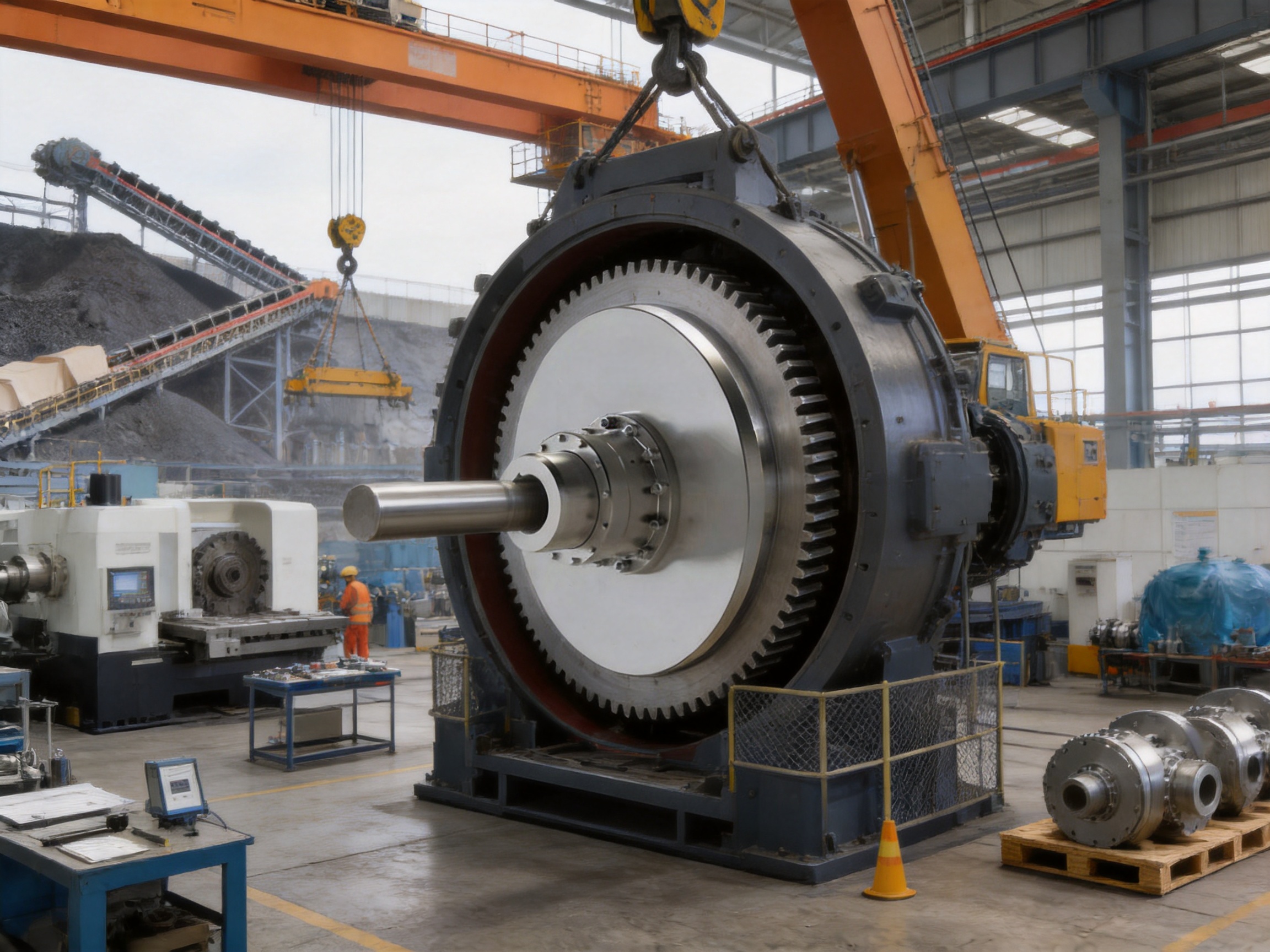
The GAP coupling provides a non-elastic flexible connection that is suitable for high torque and misalignment compensation. Its maintenance clearance for seal replacement may be valuable in remote or difficult-to-access locations, where extensive disassembly would significantly increase downtime.
7.5 Water-treatment equipment
Water-treatment facilities use large pumps, mixers, screens, sludge-handling systems, aeration equipment, and conveyors. Some systems operate continuously, while others start and stop according to process demand.
The coupling can support these applications when the required torque, speed, bore, and environmental protection are correctly specified. In wet or corrosive locations, material selection, surface treatment, sealing, and grease protection should be considered during the engineering stage.
7.6 Paper manufacturing equipment
Paper machinery depends on stable, low-vibration power transmission. Rollers, dryers, conveyors, winders, cutters, and stock-preparation equipment may require precise speed control and reliable stopping.
For higher-speed sections, the dynamic balance of the coupling and brake disc becomes especially important. The GAP1 and other smaller models offer higher allowable speeds, but the actual permissible speed must be confirmed for the complete configuration, including the selected bore, disc, key, and connected shaft.
7.7 Conveyor systems
Long conveyors may use intermediate shafts and multiple coupling arrangements. Alignment can change because of structural movement, foundation settlement, temperature variation, or maintenance work. Integrated braking can also be required on inclined conveyors or systems that must stop quickly.
The GAP coupling can be used where high torque transmission and braking integration are required. Proper alignment checks and lubrication schedules are essential because continuous operation can magnify small installation errors over time.
8. Selection and Engineering Procedure
8.1 Determine the operating torque
Begin by calculating the continuous operating torque from motor power and speed. The calculation should then be adjusted for service factor, starting conditions, shock loading, reversing cycles, and brake-related transients.
Nominal torque should not be selected solely from motor nameplate data. A machine with frequent starts and stops may impose a higher effective load than a continuously operating machine with the same motor power. Mining, lifting, and metallurgical equipment typically requires special attention to impact and overload conditions.
8.2 Check maximum braking torque
Compare the maximum brake torque with twice the selected coupling’s nominal torque. The condition Tm ≤ 2Tn must be satisfied. If the brake torque exceeds this limit, select a larger coupling or revise the braking arrangement.
Brake torque should be considered at the brake disc, coupling shaft, and gearbox output according to the actual transmission ratio. Do not compare values from different shaft locations without converting them to a common reference point.
8.3 Confirm speed
The operating speed must remain within the allowable speed for the selected model. The presence of a brake disc can influence balance and rotational behavior. If the operating speed is high, the complete rotating assembly should be evaluated for balance and critical-speed considerations.
8.4 Match the shaft bores
Confirm shaft diameters, shaft-end lengths, key dimensions, keyway orientation, and available axial installation space. Select the appropriate Y, J1, Z, or mixed bore arrangement. Shaft-hole length must be sufficient to transmit the required torque without creating excessive overhang or inadequate key engagement.
8.5 Evaluate misalignment
Measure or estimate angular, radial, and axial displacement. The coupling should be selected with a realistic allowance for operating movement. Alignment should be performed before commissioning, and the machine should be checked again after thermal stabilization or foundation settlement.
8.6 Verify space and maintenance access
Check outside diameter, brake disc diameter, overall length, guard dimensions, grease access, and the “e” dimension required for seal replacement. Adequate space should be reserved for inspection and service. A coupling that fits mechanically but cannot be maintained safely is not an appropriate selection.
8.7 Confirm environmental conditions
Specify ambient temperature, dust, moisture, corrosive substances, washdown exposure, installation altitude, and expected operating hours. These conditions influence seal selection, grease selection, surface treatment, and inspection frequency.
9. Installation and Maintenance Recommendations
9.1 Installation preparation
Before installation, inspect all coupling components for transport damage, corrosion, contamination, and dimensional conformity. Verify the model, bore arrangement, brake disc specification, and shaft requirements against the approved drawing.
Clean the shaft ends and coupling bores. Remove burrs from keyways and confirm that keys fit correctly without excessive looseness. Do not force components into position with uncontrolled impact, as this may damage bearings, seals, gear teeth, or precision-machined surfaces.
9.2 Alignment
Align the connected shafts according to the manufacturer’s installation requirements. Use suitable measuring equipment and account for thermal growth where applicable. The coupling’s flexibility should be treated as an operating allowance, not as a reason to ignore alignment.
After initial operation, inspect for unusual noise, temperature rise, grease leakage, brake vibration, and abnormal wear. A second alignment check may be useful after the machine has reached normal operating temperature.
9.3 Lubrication
Gear couplings rely on appropriate lubrication to reduce friction and wear between the gear teeth. Use the recommended grease type and quantity for the specific model and operating conditions. The technical data provide approximate grease quantities for the GAP models.
Overfilling may increase churning losses and temperature, while underfilling may result in inadequate tooth protection. Lubrication intervals should consider speed, load, temperature, contamination, and operating hours. Seals should be kept in good condition so that grease remains inside and contaminants remain outside.
9.4 Seal inspection
Inspect the seals for cracking, hardening, deformation, leakage, or displacement. The dedicated “e” dimension provides the clearance required for seal replacement. Replacing worn seals promptly helps protect the gear mesh and reduce grease loss.
9.5 Brake inspection
Check brake-disc surface condition, axial runout, mounting bolts, friction material wear, caliper alignment, and brake release. Any uneven disc wear or vibration should be investigated before continued operation.
Brake inspection should also include functional testing of emergency-stop and holding systems. The brake must release completely when commanded and apply consistently when required. A dragging brake can produce heat and unnecessary load on the coupling.
9.6 Periodic inspection
Inspection intervals should be based on the machine duty cycle and risk level. Check for abnormal tooth wear, pitting, fretting, loose fasteners, seal leakage, excessive backlash, temperature increase, and changes in vibration.
For critical equipment, record inspection findings and compare them over time. A gradual increase in vibration or temperature may identify developing alignment, lubrication, bearing, or brake problems before a serious failure occurs.
10. Why Choose a Specialized Coupling Manufacturer
A coupling is a precision mechanical component whose performance depends on more than a catalog torque rating. The gear profile, material quality, machining accuracy, bore arrangement, balance, sealing, lubrication, and assembly all influence actual service life.
A specialized manufacturer with experience in multiple coupling technologies can provide more than a standard product. It can help identify the correct coupling principle, calculate torque and braking requirements, interpret shaft drawings, develop a non-standard configuration, and provide technical support during installation and commissioning.
Zhongye Heavy Industry Technology benefits from an integrated structure covering research and development, manufacturing, sales, quality control, and technical service. Its product range serves metallurgical, mining, water, lifting, paper, port, and other industrial sectors. This application experience is valuable because similar torque ratings can produce very different coupling requirements depending on shock, speed, environment, and maintenance access.
The company also supports customized design and manufacturing. This is important for users replacing obsolete couplings, matching imported equipment, adapting to restricted installation space, or developing new machinery with special shaft and brake requirements.
11. Frequently Asked Questions
Q1: What type of coupling is the GAP model?
The GAP is a flexible coupling with non-elastic elements. It uses crowned gear teeth and an internal gear sleeve to transmit torque and compensate for shaft displacement. It also includes an integrated brake disc mounting arrangement.
Q2: What is the nominal torque range?
The GAP series covers nominal torque ratings from 630 N·m to 112,000 N·m, depending on the model from GAP1 through GAP14.
Q3: Can the coupling rotate in both directions?
Yes. The coupling is designed for clockwise and counterclockwise rotation, making it suitable for reversing drives and machinery with frequent directional changes.
Q4: What is the maximum allowable braking torque?
The maximum braking torque must not exceed twice the nominal coupling torque. The required relationship is Tm ≤ 2Tn.
Q5: Why is the brake disc mounted directly on the half coupling?
Direct mounting allows the half coupling to absorb the disc weight and braking vibration. It also creates a more direct load path between the brake and the torque-transmitting component, helping improve gear-tooth engagement during braking.
Q6: What does the “e” dimension mean?
The “e” dimension provides the clearance required for seal replacement. It allows maintenance personnel to replace seals without completely dismantling the coupling and connected transmission system.
Q7: What bore configurations are available?
The series supports several bore combinations, including Y–Y, J1–J1, Z–Z, Z1–J1, and mixed configurations such as Y–J1. The correct arrangement depends on the shaft geometry and installation requirements.
Q8: What brake disc diameters are available?
Depending on the model, standard brake disc diameters range from approximately 315 mm to 1,000 mm. The exact diameter must be selected together with the brake assembly and operating requirements.
Q9: Is the GAP coupling suitable for high-speed machinery?
Some smaller models support high rotational speeds. GAP1 has an allowable speed of up to 4,000 r/min according to the supplied technical data. Actual speed suitability must also consider the bore, disc, balance, shaft arrangement, and complete rotating system.
Q10: Does the coupling require lubrication?
Yes. The gear teeth require suitable grease to control friction and wear. The correct grease type, quantity, sealing condition, and maintenance interval should be determined according to the model and operating environment.
Q11: Can the product be customized?
Yes. Customized coupling designs can be developed for special bore dimensions, shaft lengths, brake-disc arrangements, materials, coatings, installation spaces, or other non-standard requirements. Technical evaluation should be completed before production.
Q12: Which industries commonly use this coupling?
Typical applications include lifting and port machinery, metallurgical equipment, mining machinery, water-treatment systems, paper-making equipment, conveyors, and other heavy industrial transmission systems requiring integrated braking and misalignment compensation.
Q13: Does the coupling eliminate the need for shaft alignment?
No. The coupling compensates for permitted operating misalignment, but accurate initial alignment remains essential. Excessive misalignment can cause premature tooth wear, overheating, vibration, and seal damage.
Q14: How should the coupling be selected?
Selection should consider nominal torque, peak torque, maximum braking torque, operating speed, shaft bores, shaft lengths, misalignment, brake disc diameter, environmental conditions, lubrication, installation space, and maintenance access.
12. Conclusion
The GAP drum gear coupling with brake disc provides a practical solution for heavy-duty drive systems that require high torque transmission, shaft displacement compensation, and coordinated braking. Its wide internal gear sleeve improves axial compensation, while crowned gear teeth support stable engagement under angular and radial displacement. Direct brake disc mounting helps transfer disc weight and braking vibration into the half coupling, supporting improved load distribution during stopping.
With fourteen model sizes, nominal torque ratings from 630 N·m to 112,000 N·m, brake disc diameters from approximately 315 mm to 1,000 mm, and multiple shaft-hole configurations, the series can serve a broad range of industrial machines. Its high-speed capability in smaller models and maintenance-friendly seal replacement clearance further increase its practical value.
The product is especially suitable for lifting machinery, port equipment, metallurgical and mining systems, water-treatment installations, paper machines, and conveyors. However, correct engineering remains essential. Torque, brake performance, speed, shaft geometry, alignment, lubrication, thermal conditions, and maintenance access must all be reviewed before final selection.
Supported by integrated research, manufacturing, inspection, customization, and technical service capabilities, Zhongye Heavy Industry Technology can provide both standard GAP couplings and engineered solutions for non-standard applications. For demanding industrial transmission systems, the combination of robust gear construction, integrated braking, broad specification coverage, and professional manufacturing support offers a strong alternative to conventional coupling arrangements.
References
1. Q/YG 12008X-2018, technical requirements for GAP-type drum gear couplings with brake discs.
2. Manufacturer-supplied GAP series dimensional and performance data, including torque, speed, bore, brake disc, mass, inertia, and lubrication specifications.
3. General engineering principles for gear couplings, shaft alignment, flexible coupling selection, and industrial power transmission.
4. General design practices for industrial disc brakes, braking torque calculation, thermal capacity, and emergency stopping systems.
5. Manufacturer technical information concerning heavy-duty coupling production, customization, inspection, and industrial applications.
Product: GAP Drum gear coupling with brake disc (Q/YG 12008X-2018)

- Quick Links
- About
- Products
- Our Service
- News & Events
- Contact
- Products Series
- Flexible Couplings with Non-Elastic Elements
- Flexible Couplings with Metal Elastic Elements
- Flexible Couplings with Non-Metallic Elastic Elements
- Safety Coupling
- Rigid Coupling
- Contact Us
- Tel : +86 511 8572 3800 +86 511 8572 3900
- Mobile : +86 15106109009
- Email : sales@couplingzy.com
- Add:No.1 Zhongye Yingbin Avenue, Gaozi Street, Dantu Economic Development Zone, Zhenjiang City, Jiangsu Province, China.


