:+86 15106109009
:sales@couplingzy.com


 English
 русский
 Español
 عربى
 Português
 Deutsch
 Türk
 Indonesia


DMB Key-Connected Single Diaphragm Coupling: Precision Torque Transmission for Demanding Industrial Systems
Content
- 1 Product Construction and Operating Principle
- 2 Core Performance Characteristics
- 3 Comparison with Other Coupling Technologies
- 4 Technical Specification Overview
- 5 Material and Manufacturing Advantages
- 6 Application Areas
- 7 Engineering Selection Guidelines
- 8 Installation and Maintenance Practices
- 9 Reliability, Service Life, and Total Cost
- 10 Company Manufacturing and Service Strengths
- 11 Frequently Asked Questions
- 11.1 What is a DMB key-connected single diaphragm coupling?
- 11.2 What is the largest nominal torque listed for this product?
- 11.3 Does the coupling require lubrication?
- 11.4 How does the DMB coupling compare with a snake spring coupling?
- 11.5 Can the coupling be used in corrosive environments?
- 11.6 Can a DMB coupling correct poor shaft alignment?
- 11.7 What information is required for product selection?
- 11.8 Is customization available?
- 11.9 What maintenance is recommended?
- 11.10 Are the listed allowable speeds operating targets?
- 12 Conclusion
- 13 References
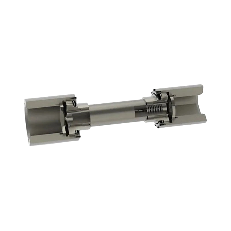
- 14 Product: DMB type key connection single type elastic diaphragm coupling(Q/YP 22004X-2018)
Modern industrial machinery increasingly depends on transmission components that can combine high torque capacity, accurate alignment control, low maintenance requirements, and dependable operation over long service intervals. The DMB type key-connected single diaphragm coupling, manufactured according to Q/YP 22004X-2018, is designed to meet these requirements through a compact all-metal construction and a carefully engineered diaphragm transmission system.
This coupling belongs to the category of flexible couplings with metal elastic elements. It connects two shafts through hubs and a single group of metallic diaphragms. The diaphragm group transmits torque while allowing controlled flexibility in response to axial, radial, and angular misalignment. Unlike couplings that rely on rubber, polyurethane, or other polymeric components, the DMB design uses a metal elastic element that can maintain its performance in demanding temperatures, high-speed conditions, corrosive environments, and lubrication-free applications.
The product range extends from compact size 00 models with a nominal torque of 9.8 N·m to size 40 models with a nominal torque of 8,100,000 N·m. This broad range allows the same basic coupling concept to serve precision machinery, high-speed equipment, power transmission systems, metallurgical machinery, mining installations, large lifting equipment, and other heavy industrial applications.
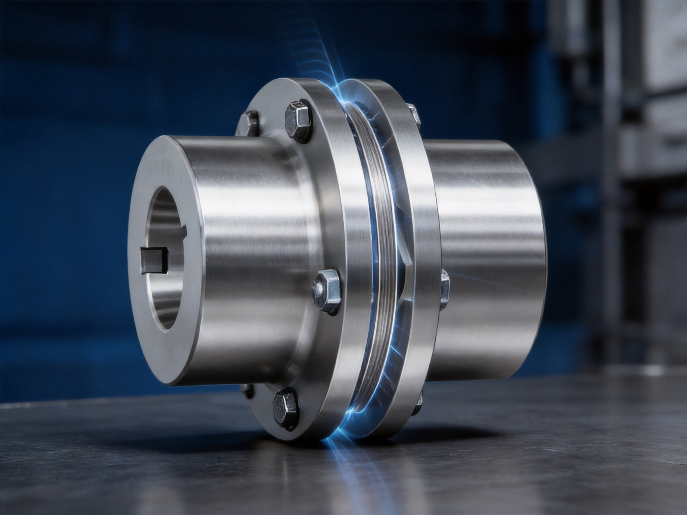
Its key-connected hub structure provides a positive mechanical connection between the shaft and coupling hub. At the same time, the diaphragm group supplies the flexibility required to compensate for installation and operating deviations. The result is a transmission component that combines high torsional rigidity with controlled flexibility, reduced backlash, long fatigue life, and low routine maintenance.
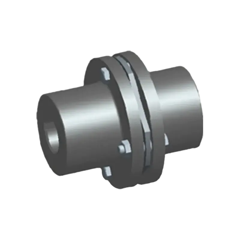
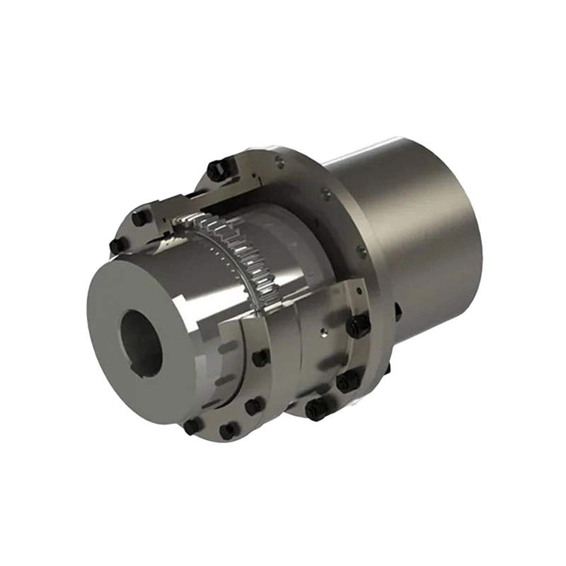
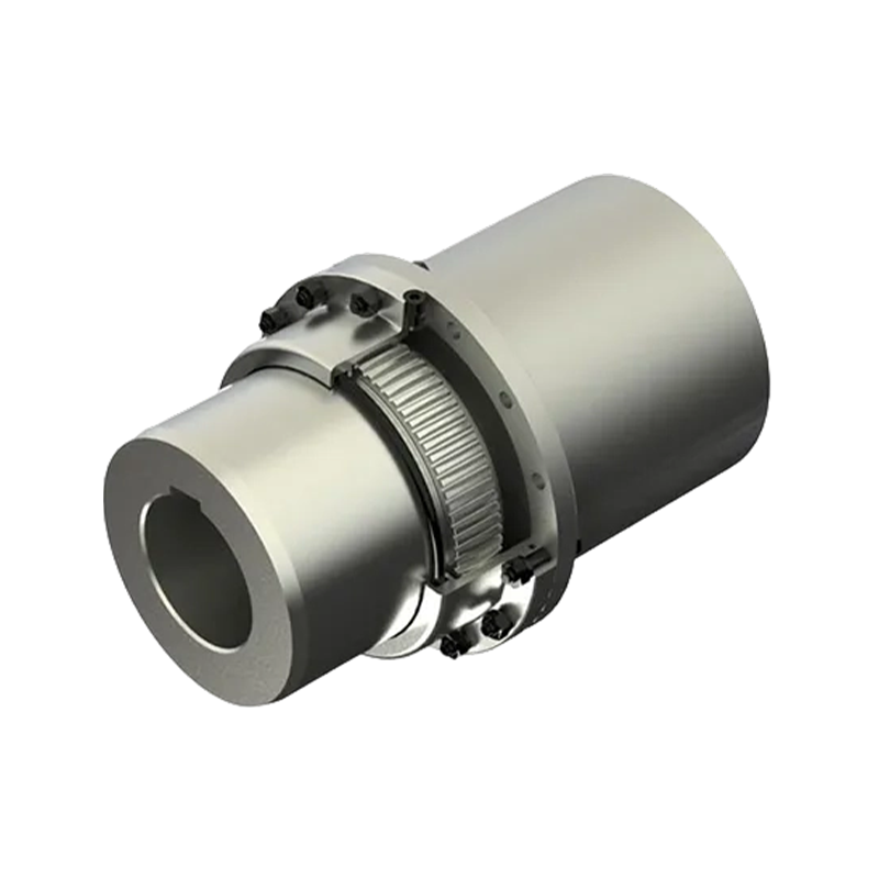
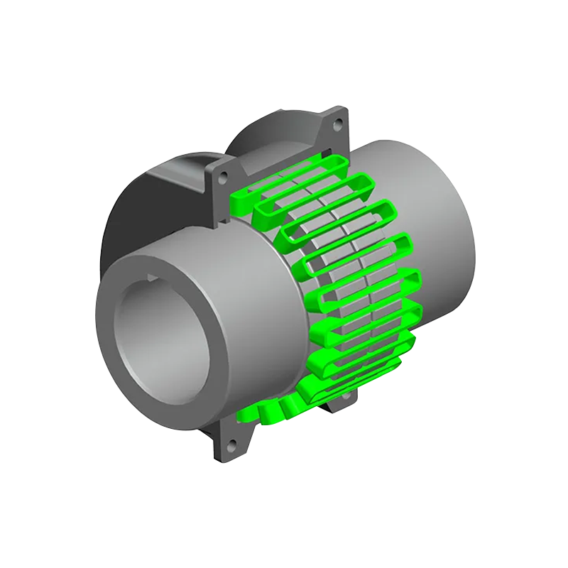
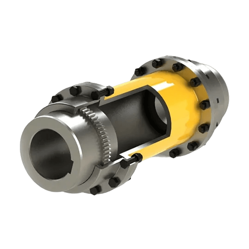
DMB type key connection single type elastic diaphragm coupling(Q/YP 22004X-2018)
Product Construction and Operating Principle
The DMB coupling is built around two wheel hubs, a single metal diaphragm group, connecting hardware, and shaft connection features based on a key connection. Each hub is installed on a shaft and secured through the keyway arrangement. The diaphragm group is attached to the hubs in a manner that enables torque to pass from one shaft to the other while allowing limited relative movement caused by shaft misalignment.
The metal diaphragm does not operate like a conventional flexible insert that deforms freely in every direction. Instead, it is carefully designed to provide predictable elastic deformation. During operation, the diaphragm remains highly rigid in the circumferential direction, which supports efficient torque transmission and accurate angular positioning. In the axial, radial, and angular directions, it can flex within the specified allowable compensation values.
This operating principle gives the coupling two important characteristics. First, the connection has high torsional stiffness, which helps preserve the timing and phase relationship between the driving and driven shafts. Second, the coupling can accommodate unavoidable alignment deviations without imposing excessive additional loads on shafts, bearings, gearboxes, motors, or other connected equipment.
The single diaphragm group contributes to a relatively compact axial arrangement. Compared with longer multi-element coupling assemblies, the DMB structure can reduce the space required around the shaft connection. This is particularly valuable where equipment layouts are crowded or where access for installation and inspection is limited.
The key connection is also suitable for applications requiring a positive shaft-to-hub torque path. It can provide reliable torque transfer when correctly designed and installed, while the diaphragm assembly supplies the flexibility that a fully rigid keyed connection would not provide. Shaft dimensions, keyway details, fits, fastening torque, and installation tolerances should be checked against the actual application before final selection.
Core Performance Characteristics
High Torque Transmission Capacity
The DMB type range covers a very large torque spectrum. The smallest listed model has a nominal torque of 9.8 N·m, while the largest model reaches 8,100,000 N·m. This makes the product suitable for both high-speed precision drives and extremely large industrial transmission systems.
The torque range is supported by progressively larger shaft bores, outside diameters, axial dimensions, diaphragm structures, and masses. As the model size increases, the allowable speed decreases to reflect the mechanical requirements of larger rotating assemblies. This relationship between torque, diameter, and allowable speed is important when selecting a coupling. A model should not be chosen only by nominal torque; operating speed, shaft diameter, misalignment, inertia, environmental conditions, and transient loading must also be considered.
For industrial systems with starting shocks, reversing loads, frequent acceleration, or other dynamic conditions, the nominal torque should be supplemented by an appropriate service factor. The actual selection should consider the motor or engine output, operating duty, peak torque, torsional vibration, braking conditions, and possible overloads.
Accurate Compensation of Misalignment
No practical shaft system remains perfectly aligned under all operating conditions. Installation tolerances, foundation movement, thermal expansion, bearing clearance, shaft deflection, manufacturing deviations, and load-induced deformation can create axial, radial, or angular misalignment.
The diaphragm group is designed to compensate for these deviations within specified limits. The table provides allowable axial compensation in millimeters and allowable angular compensation in degrees or minutes. For example, smaller models provide angular compensation of approximately 1 degree, while larger models use values such as 30 or 20 minutes. The allowable axial compensation varies according to model size and design geometry.
Misalignment compensation should not be treated as permission to omit alignment work. A flexible coupling is intended to accommodate operational movement, not to correct poor installation. Excessive initial misalignment can increase diaphragm stress, reduce fatigue life, raise bearing loads, and create unwanted vibration. Accurate shaft alignment remains one of the most important factors in achieving the expected service life.
High Torsional Rigidity
Metal diaphragm couplings generally provide greater torsional rigidity than couplings that use soft elastomeric elements. This characteristic is beneficial where the system requires precise torque transmission, accurate speed synchronization, rapid response, or stable positioning.
High torsional rigidity helps reduce angular displacement between the two shafts under load. It can also support the operation of equipment where transmission lag or torsional wind-up would negatively affect performance. Examples include precision drives, high-speed machinery, controlled motion systems, pumps, compressors, generators, and equipment with strict phase or speed requirements.
At the same time, the diaphragm supplies elastic compliance in selected directions. This balance between rigidity and flexibility is one of the primary reasons to use a diaphragm coupling instead of a fully rigid flange connection.
Lubrication-Free Operation
The DMB coupling does not depend on grease or oil to maintain the flexibility of its principal transmission element. Because the diaphragm is metallic, the coupling can operate without regular lubrication of the flexible element. This can simplify maintenance schedules and reduce the risk of lubricant leakage or contamination.
Lubrication-free operation is especially valuable in environments where access is difficult, where regular shutdowns are expensive, or where oil and grease could interfere with production. It can also be advantageous in high-speed applications where lubricant migration or temperature rise would create additional concerns.
Although the diaphragm itself does not require routine lubrication, other parts of the connected machine may have their own lubrication requirements. Fasteners, keyways, shaft fits, guards, bearings, and surrounding equipment should be maintained according to the applicable technical instructions.
Resistance to Temperature and Corrosion
The product description identifies stainless steel or alloy steel as the principal material options for the all-metal structure. Material selection can be adapted to the operating environment, required strength, fatigue conditions, and corrosion exposure.
Metallic construction is generally more stable than polymeric flexible elements when exposed to elevated temperatures, temperature cycling, oil mist, ultraviolet exposure, industrial chemicals, or harsh atmospheric conditions. In corrosive environments, the material grade, surface treatment, fastener material, and sealing or guarding arrangement should be selected together.
It is important to distinguish between general corrosion resistance and suitability for a specific chemical environment. The final material selection should take account of humidity, salt spray, process chemicals, pH, temperature, cleaning agents, and any galvanic contact between dissimilar materials.
Reduced Rotational Inertia
The compact design of the DMB coupling helps limit the rotating mass and moment of inertia of the transmission assembly. Reduced inertia can improve acceleration and deceleration response, reduce the energy needed for speed changes, and lower the dynamic load imposed on the drive system.
Low rotational inertia is particularly important for servo-related equipment, high-speed rotating machinery, indexing systems, and drives that frequently start and stop. A lighter coupling can also make installation and replacement easier, although large industrial models naturally require suitable lifting equipment and handling procedures.
Vibration and Shock Management
The diaphragm’s elastic properties allow the coupling to absorb certain operational disturbances and accommodate movement between the connected shafts. It is not a substitute for a dedicated torsional vibration damper, but it can contribute to smoother operation by reducing the transmission of certain alignment-related disturbances and mechanical impacts.
A properly selected and aligned coupling can help reduce abnormal vibration, noise, and wear in connected equipment. Conversely, an incorrectly selected coupling may amplify torsional excitation or experience excessive fatigue. For systems with pronounced resonance, cyclic torque, reciprocating loads, or rapid torque reversals, a torsional analysis should be completed before final selection.
Comparison with Other Coupling Technologies
Comparison with Snake Spring Couplings
Snake spring couplings are valued for their ability to absorb shock loads and provide damping through a spring grid or serpentine spring element. They can be highly effective in heavy-duty applications where impact loading and torsional vibration are major concerns.
The DMB diaphragm coupling takes a different approach. Its all-metal diaphragm provides high torsional rigidity, accurate shaft synchronization, and compensation for axial, radial, and angular deviations. It does not rely on a lubricated spring grid or an elastomeric component. This can make it preferable when the application prioritizes precision, high-speed stability, corrosion resistance, compact dimensions, and minimal routine maintenance.
A snake spring coupling may be attractive where strong shock absorption and replaceable flexible elements are central requirements. The DMB coupling may be more suitable where precise torque transmission, a clean lubrication-free design, long fatigue life, and predictable misalignment compensation are more important. The correct choice depends on the load profile, speed, environmental conditions, maintenance philosophy, and torsional requirements of the complete machine.
Comparison with Elastomeric Couplings
Elastomeric couplings use rubber, polyurethane, or similar materials to provide flexibility and damping. Their advantages can include simple construction, low cost, electrical isolation, and effective absorption of certain vibrations.
However, elastomeric elements can be affected by temperature, aging, chemical exposure, ultraviolet radiation, oil, and compression set. Their dynamic properties may also change over time. The DMB coupling avoids many of these limitations by using a metallic diaphragm element. Its performance is less dependent on polymer aging and is generally more stable across a wider range of operating conditions.
Elastomeric couplings can still be the better choice when high damping, electrical isolation, low initial cost, or simple replacement is required. The DMB coupling is generally favored for high precision, high speed, high temperature, or severe industrial service where metal fatigue design and alignment control are more important than soft damping.
Comparison with Gear Couplings
Gear couplings can transmit very high torque in a relatively compact package and may accommodate significant misalignment. They are widely used in heavy industrial machinery. However, they typically require regular lubrication and careful attention to tooth wear, seal condition, and lubricant contamination.
The DMB coupling offers a lubrication-free flexible element and avoids sliding gear tooth contact in the principal misalignment mechanism. This can reduce routine maintenance and eliminate concerns related to grease leakage. It may also produce less mechanical noise when correctly installed.
Gear couplings may remain preferable for some very high-torque applications, especially where their established design, compact radial dimensions, or specific misalignment capacity is required. The DMB product range nevertheless provides an attractive alternative when maintenance reduction, high torsional rigidity, and clean operation are primary objectives.
Comparison with Rigid Couplings
Rigid couplings provide direct shaft connection with essentially no intentional flexibility. They are suitable only where the shafts are accurately aligned and remain aligned throughout operation. Any movement or misalignment is transferred directly to the connected machine.
The DMB design provides a more forgiving connection while retaining substantially greater torsional stiffness than many soft flexible couplings. It can protect bearings and shafts from alignment-related loads and compensate for thermal or structural movement within the specified limits.
Where shaft alignment is permanently precise and no compensation is required, a rigid coupling may be adequate. Where operational movement is unavoidable, the DMB diaphragm coupling provides a safer and more versatile engineering solution.
Technical Specification Overview
The following table summarizes selected basic parameters across the DMB type key-connected single diaphragm coupling range. The values are based on the supplied product data. Final selection should be confirmed against the manufacturer’s technical drawings, application calculations, and operating conditions.
| Type | Nominal Torque (N·m) | Allowable Speed (r/min) | Maximum Bore (mm) | Outside Diameter D (mm) | Length L (mm) | Axial Compensation (mm) | Angular Compensation | Mass (kg) |
|---|---|---|---|---|---|---|---|---|
| 00 | 9.8 | 20,000 | 20 | 57 | 44.9 | ±0.8 | 1° | 0.14 |
| 01 | 33 | 20,000 | 22 | 68 | 58.1 | ±0.8 | 1° | 0.60 |
| 02 | 90 | 20,000 | 32 | 81 | 58.6 | ±1.0 | 1° | 1.10 |
| 03 | 173 | 18,000 | 35 | 93 | 66.4 | ±1.2 | 1° | 1.70 |
| 05 | 420 | 13,000 | 50 | 126 | 95.7 | ±1.6 | 45′ | 4.30 |
| 08 | 2,080 | 10,000 | 82 | 194 | 145 | ±2.2 | 45′ | 16.70 |
| 10 | 4,900 | 8,000 | 108 | 246 | 201.9 | ±2.6 | 45′ | 35.40 |
| 12 | 8,900 | 6,300 | 110 | 276 | 273.5 | ±1.8 | 45′ | 57.20 |
| 16 | 47,120 | 3,900 | 180 | 410 | 457.5 | ±2.2 | 30′ | 191 |
| 20 | 102,100 | 2,800 | 255 | 556 | 642.5 | ±2.5 | 30′ | 530 |
| 24 | 200,000 | 1,400 | 305 | 680 | 744 | ±3.5 | 30′ | 980 |
| 28 | 500,000 | 1,100 | 400 | 875 | 850 | ±4.8 | 20′ | 1,700 |
| 32 | 1,250,000 | 820 | 500 | 1,160 | 1,110 | ±5.8 | 20′ | 3,500 |
| 36 | 3,020,000 | 570 | 710 | 1,670 | 1,575 | ±7.2 | 20′ | 7,900 |
| 40 | 8,100,000 | 400 | 1,030 | 2,400 | 2,060 | ±8.2 | 20′ | 21,100 |
The complete range includes every size from 00 through 40. Intermediate models provide gradual increases in nominal torque, maximum bore, outside diameter, allowable axial compensation, and mass. The largest models are intended for very high-capacity industrial systems and require careful engineering review, transportation planning, lifting provisions, and installation control.
Material and Manufacturing Advantages
Integrated Research, Development, and Production
The manufacturer operates as an integrated research, development, manufacturing, and sales enterprise. This structure is important for coupling production because performance depends not only on the basic design but also on material control, machining accuracy, heat treatment, assembly quality, balancing, inspection, and application engineering.
An integrated organization can transfer field feedback into product improvements more efficiently. It can also coordinate non-standard design work with production capabilities, helping customers obtain a coupling adapted to unusual shaft sizes, installation constraints, torque requirements, or environmental conditions.
Heavy and Precision Workshop Capabilities
The company’s new workshop covers approximately 16,463.52 square meters. It includes a heavy workshop of approximately 5,500 square meters, a precision workshop of approximately 4,600 square meters, office and engineering facilities, a warehouse, and supporting infrastructure.
The combination of heavy and precision manufacturing areas is suitable for a product family that spans from very small, high-speed couplings to extremely large, high-torque assemblies. Heavy equipment and handling resources are necessary for processing large hubs and diaphragms, while precision machining resources are required for bore dimensions, keyways, mounting faces, concentricity, flatness, and assembly interfaces.
Large couplings must maintain dimensional consistency despite their size and mass. Even relatively small deviations in a large rotating component can influence balance, runout, bearing load, and operating vibration. A dedicated precision manufacturing environment helps control these factors during machining and inspection.
Material and Process Control
Metal diaphragm couplings depend heavily on the fatigue performance of their flexible elements. Material quality, thickness consistency, surface condition, heat treatment, hole geometry, edge finishing, and assembly stress all influence the service life of the diaphragm group.
Alloy steel and stainless steel options can be selected according to strength, corrosion resistance, fatigue requirements, temperature, and customer application. Proper material traceability and controlled processing help ensure that the diaphragm behaves consistently under repeated elastic deformation.
Hubs and other structural components also require controlled machining. Keyways must be accurately formed, mounting surfaces must remain square and concentric, and fastener holes must be positioned correctly. Dimensional errors at these interfaces can create uneven loading and unnecessary stress in the diaphragm assembly.
Quality Inspection and Testing
The company identifies strict quality control and advanced testing facilities among its principal advantages. For diaphragm couplings, quality assurance can include incoming material verification, dimensional inspection, hardness checks, surface inspection, runout measurement, balance verification, fastener inspection, and final assembly checks.
Depending on the order and application, inspection may also include non-destructive testing or specialized performance verification. Such measures are particularly important for large couplings used in critical equipment, where an unexpected transmission failure could cause extended downtime or damage to connected machinery.
Quality control should cover the complete product lifecycle, from design calculation through machining, assembly, packaging, shipment, installation, and after-sales support. The company’s ISO 9001-related quality management practices provide a structured basis for consistent production and documentation.
Customization and Non-Standard Design
Standardized models simplify selection and improve delivery efficiency, but industrial equipment often includes non-standard shaft diameters, unusual spacing, special mounting arrangements, limited access, or specific material requirements. The manufacturer undertakes the design and manufacture of non-standard couplings to address such conditions.
Customization may include modified bore dimensions, alternative keyway arrangements, special hub lengths, different flange interfaces, corrosion-resistant materials, adapted diaphragm characteristics, special balancing requirements, customized guards, or dimensional changes required by the equipment layout.
Non-standard design should begin with complete technical information. The customer should provide rated power, speed, nominal torque, peak torque, shaft diameters, shaft extensions, keyway dimensions, axial spacing, expected misalignment, environmental conditions, start-stop frequency, temperature, and available installation space. Drawings and load data are especially useful for confirming that the customized design will operate safely.
Application Areas
Metallurgical Equipment
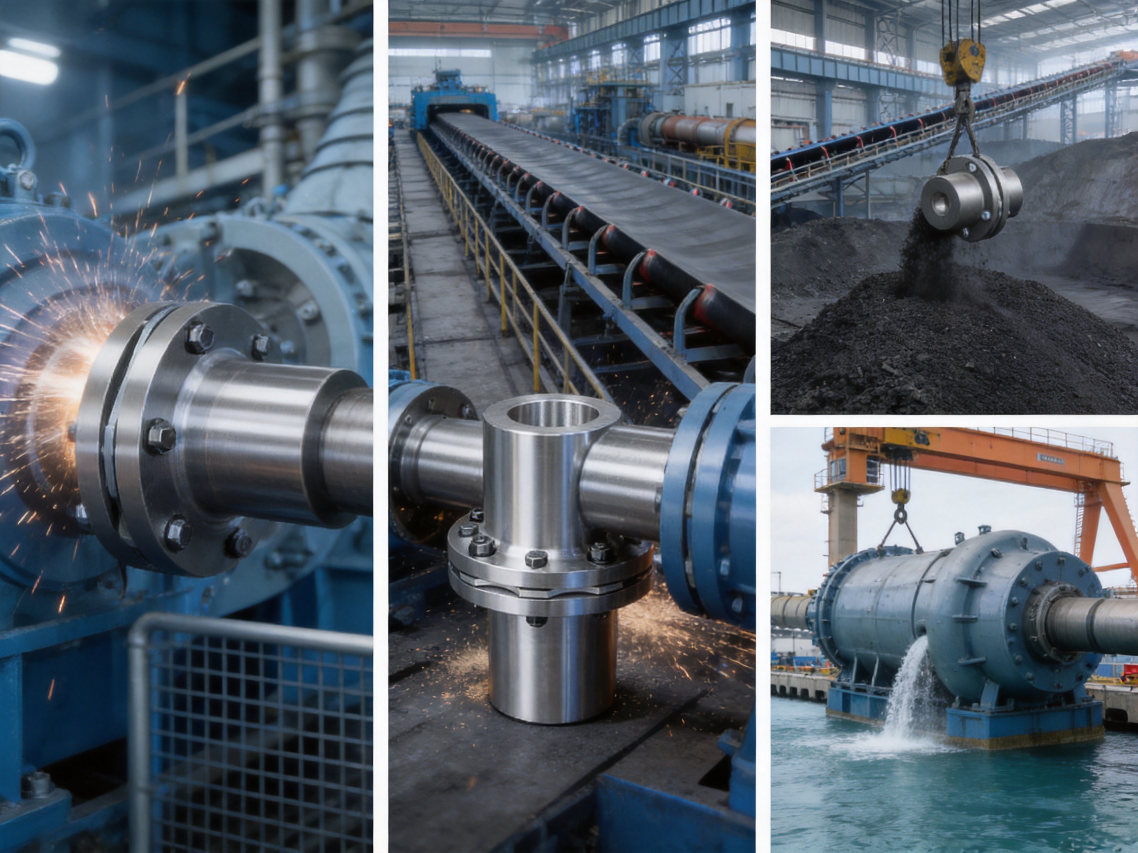
Steel mills and other metallurgical plants frequently use high-power drives, rolling equipment, conveyors, pumps, fans, and auxiliary machinery. These installations may experience high torque, shock loading, heat, dust, vibration, and difficult maintenance access.
The DMB coupling can be considered where high torque capacity, metal construction, and reduced lubrication requirements are valuable. Correct selection must account for rolling loads, transient torque, operating cycles, thermal effects, and the possibility of rapid load changes.
Mining Machinery
Mining equipment operates in abrasive, dusty, and often remote environments. Conveyors, crushers, hoists, pumps, and processing machines may be exposed to severe impact loads and long operating hours.
The metal diaphragm design can provide a dependable connection where contamination makes frequent lubrication difficult. However, applications with very high impact or severe torsional shock should be analyzed carefully. In some systems, a coupling with greater damping may be preferable, while in others the DMB design can be combined with suitable drive control and mechanical protection.
Water and Pumping Equipment
Pumps and water-treatment equipment benefit from reliable shaft alignment and low routine maintenance. Diaphragm couplings can be used in pump drives where the operating speed, torque, shaft diameter, and alignment conditions fall within the product range.
In water, wastewater, and coastal installations, corrosion protection deserves particular attention. Stainless steel or suitable coatings may be specified according to the atmosphere and chemical exposure. Guards and drainage arrangements should also be considered to prevent standing water around the rotating assembly.
Lifting and Port Equipment
Cranes, hoists, winches, ship-loading systems, and port machinery require dependable torque transmission under frequent starts, stops, braking events, and load changes. Coupling selection should consider emergency braking, reversal, acceleration, duty class, and the possibility of suspended-load shock.
The DMB coupling’s positive key connection and high torque capacity can be valuable in these systems. Nevertheless, the complete drive train should be reviewed for overloads and transient conditions. Braking torque can be significantly higher than steady operating torque and must be included in the calculation.
Paper and Process Machinery
Paper machines and process lines often require accurate speed coordination, long running hours, stable operation, and low vibration. Their operating environments may include moisture, heat, chemicals, and limited access to drive components.
The DMB coupling can support high torsional accuracy and lubrication-free operation. Its low maintenance characteristics may reduce planned shutdown requirements, while its metal construction can provide better stability than some polymeric couplings in elevated-temperature or chemically demanding areas.
Power and Energy Systems
Power-generation auxiliaries, generators, turbines, compressors, and large pumps require coupling systems with predictable dynamic behavior and strong reliability. High-speed models in the DMB range can support applications where torsional rigidity, balance, and alignment accuracy are critical.
High-speed installations require special attention to rotor dynamics, balancing grade, critical speeds, guard design, and installation precision. The allowable speed listed for each model is a fundamental limit, not a target that should be exceeded. The coupling should be selected with appropriate safety margins for the complete operating range.
Engineering Selection Guidelines
Step One: Determine Operating Torque
The first selection step is to determine the actual transmitted torque. For a rotating machine, torque can be calculated from power and speed, but rated torque alone is not enough. Starting torque, overload torque, braking torque, reversing torque, and cyclic torque must also be reviewed.
The selected nominal torque should exceed the calculated application torque after applying an appropriate service factor. The service factor depends on the driven machine, duty cycle, load variation, motor characteristics, operating hours, and shock level.
Step Two: Check Speed
The coupling’s allowable speed must be higher than the maximum continuous operating speed and any permitted overspeed condition. The speed limit should be evaluated together with rotor balance, shaft geometry, coupling orientation, guard design, and critical-speed behavior.
Small DMB models can operate at speeds up to 20,000 r/min according to the supplied data. The allowable speed decreases as model size and torque capacity increase, reaching 400 r/min for size 40. The selected model must satisfy both torque and speed requirements simultaneously.
Step Three: Confirm Shaft and Bore Dimensions
The coupling bore must match the shaft diameter and keyway arrangement. The shaft should have adequate strength and sufficient engagement length. Shaft shoulders, key dimensions, fits, and axial retention must be checked during the design stage.
Where the required bore exceeds the listed maximum or where a special shaft interface is necessary, a customized design may be considered. Any modification should be approved through engineering review rather than performed informally at the installation site.
Step Four: Evaluate Misalignment
Measure or calculate the expected axial, radial, and angular misalignment under both cold and operating conditions. Thermal growth can change alignment significantly, especially in long machines, large pumps, compressors, and systems with different operating temperatures at each shaft.
The expected misalignment must remain within the allowable compensation values. If the application approaches the listed limit, additional alignment margin should be provided. Excessive misalignment can reduce fatigue life even when the coupling initially appears to operate normally.
Step Five: Review Environment and Maintenance
Temperature, humidity, dust, chemicals, water spray, salt, vibration, and installation accessibility should be recorded. Material selection and surface protection should match the environment.
The coupling should also be protected by a suitable guard. The guard must prevent accidental contact with rotating parts while allowing adequate ventilation and inspection access. It should not interfere with coupling movement or impose loads on the coupling housing.
Installation and Maintenance Practices
Pre-Installation Inspection
Before installation, inspect the coupling for shipping damage, corrosion, burrs, missing fasteners, and contamination. Confirm the model number, bore dimensions, keyway details, and supplied accessories. Do not install a coupling if the diaphragm group has been bent, dented, or visibly damaged.
Check the shafts for correct diameter, surface condition, keyway accuracy, shoulder position, and axial length. Remove dirt, burrs, and excessive paint from the mounting surfaces. Ensure that the shaft and hub fits are compatible with the approved installation method.
Shaft Alignment
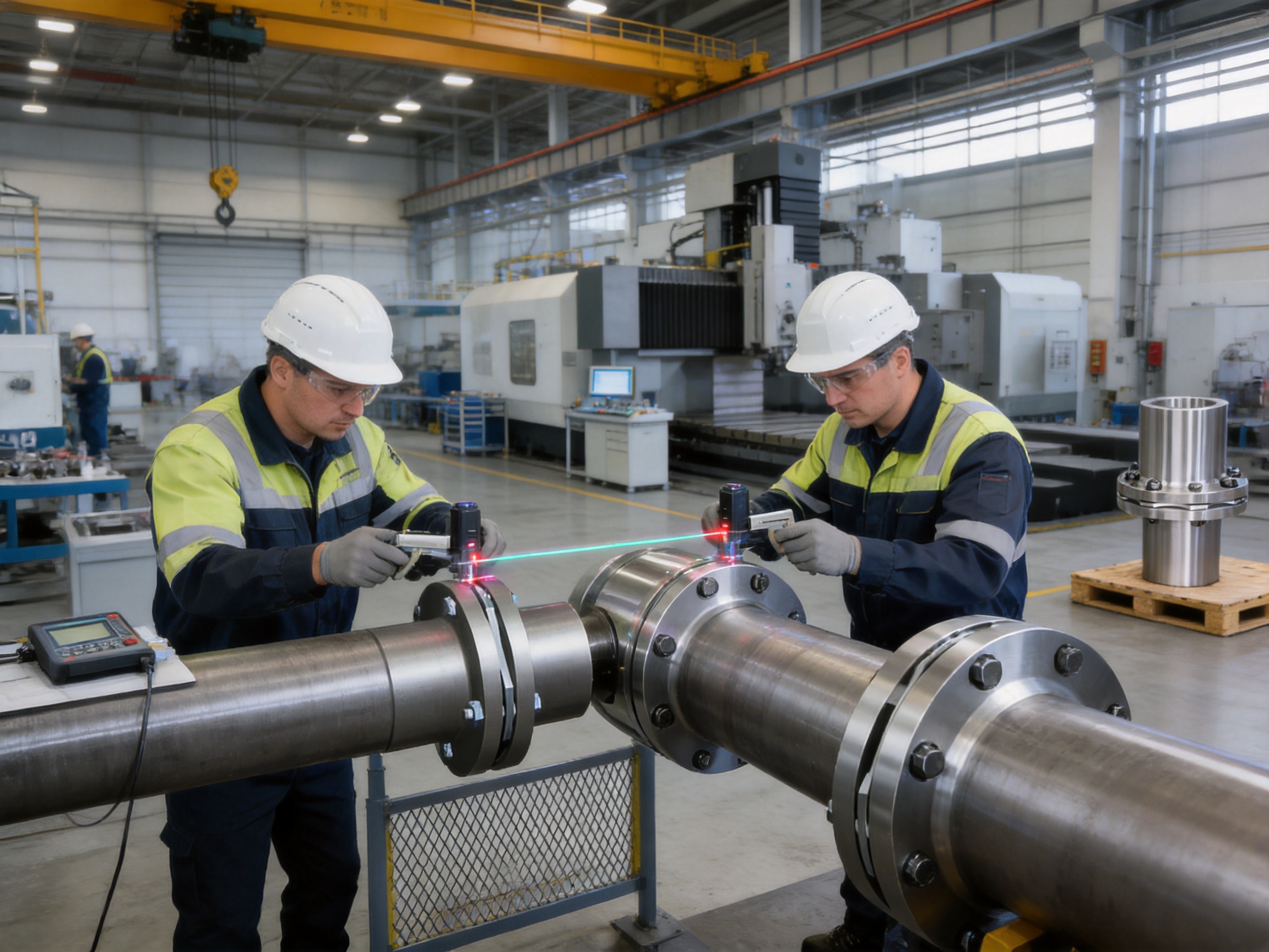
Align the shafts using appropriate dial-indicator, laser, or optical alignment equipment. Measure angular and offset alignment at multiple rotational positions where practical. Alignment should be completed at the actual installed condition, taking into account soft foot, thermal growth, pipe strain, foundation movement, and equipment settling.
Do not use the coupling to pull misaligned equipment into position. Doing so can preload the diaphragm group and cause premature fatigue. Correct the position of the motor, gearbox, pump, or driven machine first, then install and inspect the coupling.
Fastener Tightening
Fasteners should be tightened according to the approved torque values and sequence. Uneven tightening can distort the diaphragm group or create non-uniform load distribution. Locking methods should be applied as specified for the particular design and operating conditions.
Where the coupling is installed in a high-speed or safety-critical system, fastener identification, torque records, and inspection documentation should be retained. Any replacement fastener must meet the required grade, dimension, surface treatment, and thread specification.
Initial Run and Inspection
After installation, rotate the system manually where possible to confirm clearance and freedom from interference. Install all guards before powered operation. Conduct an initial run at low speed if the equipment permits, then gradually increase speed while monitoring vibration, noise, temperature, and abnormal movement.
After the first operating period, inspect the coupling and adjacent equipment. Check fasteners, shaft movement, guard clearance, and signs of fretting or contact. A follow-up inspection is especially advisable after the first start-up of a newly installed or customized coupling.
Routine Maintenance
The DMB coupling generally requires less routine maintenance than lubricated gear or grid couplings. Even so, regular visual inspection is recommended. Inspection intervals should be based on operating hours, duty severity, safety requirements, and the consequences of failure.
Look for cracks, deformation, corrosion, fretting, loose fasteners, unusual wear, and evidence of contact with the guard. Monitor changes in vibration or operating noise. Any sudden change should be investigated rather than attributed automatically to the coupling.
During planned shutdowns, verify alignment where practical and inspect the diaphragm group closely. If the coupling has experienced an overload, collision, severe vibration event, or unexpected shutdown, it should be removed from service until it has been evaluated.
Reliability, Service Life, and Total Cost
The economic value of a coupling is determined by more than its purchase price. Installation time, lubrication requirements, inspection labor, replacement frequency, unplanned downtime, energy consumption, and damage to connected equipment all influence the total cost of ownership.
The DMB coupling can reduce several of these costs through its lubrication-free diaphragm construction, long fatigue-life potential, compact arrangement, and broad application range. Reduced maintenance does not mean maintenance-free operation; it means that maintenance can be focused on alignment, fasteners, inspection, and the surrounding drive system instead of frequent lubrication and flexible-element replacement.
Long service life depends on correct selection and operation. The coupling must not be overloaded, oversped, excessively misaligned, improperly assembled, or exposed to an environment beyond its material capability. A well-designed coupling can provide reliable service for many years, while an incorrectly selected coupling may fail prematurely regardless of its nominal quality.
Company Manufacturing and Service Strengths
The manufacturer provides a broad portfolio of coupling products, including toothed couplings, elastic sleeve pin couplings, elastic pin couplings, gear couplings with elastic pins, universal couplings, tire couplings, jaw couplings, star couplings, diaphragm couplings, drum couplings, grid couplings, Oldham couplings, flange couplings, clamp-shell couplings, roller-chain couplings, safety couplings, and customized non-standard products.
This broad product portfolio gives the engineering team experience across multiple coupling technologies. Such experience is useful when comparing alternatives for a customer’s complete transmission system. Instead of promoting only one coupling principle, an experienced manufacturer can consider whether a diaphragm, gear, grid, elastomeric, rigid, safety, or customized design is best suited to the actual load and environment.
The company serves metallurgical, mining, water, lifting, paper, port, and other industrial sectors. Its manufacturing resources include heavy production, precision machining, warehousing, testing, engineering, and customer-support capabilities. These strengths support both standard product supply and application-specific design.
Pre-sale technical support can assist with model selection, shaft interface confirmation, torque calculations, misalignment evaluation, material selection, and installation planning. For non-standard projects, design support can help transform equipment drawings and operating data into a practical coupling specification.
After-sales service is also important for large industrial couplings. Installation guidance, inspection recommendations, spare parts support, troubleshooting, and technical documentation can reduce the risk of incorrect field operation. A coupling manufacturer’s responsibility should extend beyond shipment to the successful integration of the product into the customer’s machine.
Frequently Asked Questions
What is a DMB key-connected single diaphragm coupling?
It is a flexible shaft coupling that uses a key-connected hub arrangement and a single metallic diaphragm group to transmit torque between two shafts. The diaphragm provides controlled flexibility for axial, radial, and angular misalignment while maintaining high torsional rigidity.
What is the largest nominal torque listed for this product?
The largest listed model is type 40, with a nominal torque of 8,100,000 N·m, equivalent to 8,100 kN·m. It has a maximum bore of 1,030 mm, an outside diameter of 2,400 mm, an allowable speed of 400 r/min, and a listed mass of approximately 21,100 kg.
Does the coupling require lubrication?
The metallic diaphragm element is designed for operation without routine lubrication. This is one of the main advantages over many gear or grid couplings. However, the shafts, keys, fasteners, bearings, and other connected machine components must still be maintained according to their own technical requirements.
How does the DMB coupling compare with a snake spring coupling?
A snake spring coupling emphasizes shock absorption and torsional damping through its spring element. The DMB coupling emphasizes high torsional rigidity, precise torque transmission, lubrication-free operation, metal construction, and controlled misalignment compensation. The better choice depends on the application’s shock, vibration, speed, maintenance, and precision requirements.
Can the coupling be used in corrosive environments?
It can be designed for demanding environments through appropriate material and surface-treatment selection. Stainless steel or suitable alloy steel may be considered, but the exact material must be matched to the chemicals, temperature, humidity, salt exposure, and cleaning conditions of the application.
Can a DMB coupling correct poor shaft alignment?
No. It can compensate for limited operational misalignment within its specified values, but it should not be used to correct poor installation. Excessive initial misalignment can overload the diaphragm and connected bearings and reduce service life.
What information is required for product selection?
Important information includes rated power, operating speed, nominal and peak torque, motor type, load characteristics, shaft diameters, keyway details, shaft extensions, axial spacing, expected misalignment, ambient temperature, corrosion exposure, start-stop frequency, braking conditions, installation space, and required standards.
Is customization available?
Yes. The manufacturer undertakes non-standard coupling design and production. Customization may address bore dimensions, keyways, hub length, mounting interfaces, materials, balancing, diaphragm characteristics, corrosion protection, and special installation limitations.
What maintenance is recommended?
Recommended maintenance includes periodic visual inspection, alignment verification, fastener checks, corrosion inspection, vibration monitoring, guard inspection, and examination of the diaphragm group during planned shutdowns. The inspection interval should reflect operating speed, load severity, safety importance, and environmental conditions.
Are the listed allowable speeds operating targets?
No. They are maximum listed allowable speeds for the respective models under specified design conditions. The actual application should include appropriate engineering margin and should also be evaluated for balance, rotor dynamics, critical speed, and transient overspeed.
Conclusion
The DMB type key-connected single diaphragm coupling is a high-performance transmission solution for industrial systems that require accurate torque transfer, controlled misalignment compensation, high torsional rigidity, long service life, and reduced maintenance. Its all-metal diaphragm construction provides advantages over many elastomeric, lubricated gear, grid, and spring-based couplings in applications where temperature stability, corrosion resistance, cleanliness, and precision are important.
The extensive size range, from 9.8 N·m to 8,100,000 N·m, allows the same product principle to serve compact high-speed machinery and very large heavy-duty systems. Its key-connected hub structure supports positive torque transmission, while the diaphragm group accommodates operational movement without sacrificing transmission accuracy.
Product performance depends on more than the coupling design itself. Correct model selection, adequate torque margin, speed verification, shaft compatibility, accurate alignment, proper fastener tightening, suitable guarding, and routine inspection are all essential. When these factors are controlled, the DMB coupling can contribute to lower downtime, reduced maintenance effort, stable operation, and longer service life for the complete transmission system.
The manufacturer’s integrated research, development, heavy manufacturing, precision machining, testing, customization, and technical-support capabilities further strengthen the product offering. For standard and non-standard applications alike, engineering cooperation at the design stage can help ensure that the coupling is correctly matched to the equipment, environment, and operating duty.
References
Q/YP 22004X-2018, Technical Requirements for DMB Type Key-Connected Single Diaphragm Couplings.
Manufacturer-supplied DMB coupling product specifications and dimensional tables.
Manufacturer technical information on metal elastic-element flexible couplings and industrial transmission products.
ISO 9001, Quality Management Systems — Requirements.
General engineering principles for shaft alignment, flexible coupling selection, torsional analysis, rotating equipment inspection, and industrial machinery maintenance.
Product: DMB type key connection single type elastic diaphragm coupling(Q/YP 22004X-2018)

- Quick Links
- About
- Products
- Our Service
- News & Events
- Contact
- Products Series
- Flexible Couplings with Non-Elastic Elements
- Flexible Couplings with Metal Elastic Elements
- Flexible Couplings with Non-Metallic Elastic Elements
- Safety Coupling
- Rigid Coupling
- Contact Us
- Tel : +86 511 8572 3800 +86 511 8572 3900
- Mobile : +86 15106109009
- Email : sales@couplingzy.com
- Add:No.1 Zhongye Yingbin Avenue, Gaozi Street, Dantu Economic Development Zone, Zhenjiang City, Jiangsu Province, China.


