:+86 15106109009
:sales@couplingzy.com


 English
 русский
 Español
 عربى
 Português
 Deutsch
 Türk
 Indonesia


QGCA Cylindrical Bore Spherical Roller Coupling: Heavy-Duty Torque Transmission, Misalignment Compensation, and Reliable Industrial Performance
Content
- 1 1. Product Overview and Operating Purpose
- 2 2. Key Technical Characteristics
- 3 3. Advantages Compared with Conventional Coupling Designs
- 4 4. Performance in Severe Operating Conditions
- 5 5. Main Dimensions and Selection Data
- 6 6. Shaft Bore and Installation Flexibility
- 7 7. Wear Monitoring and Maintenance
- 8 8. Manufacturing Strengths and Engineering Capability
- 9 9. Industrial Applications
- 10 10. Coupling Selection Method
- 11 11. Installation and Commissioning Recommendations
- 12 12. Q&A
- 12.1 Q1: What type of coupling is the QGCA product?
- 12.2 Q2: What does the cylindrical bore mean?
- 12.3 Q3: How much angular misalignment can the coupling compensate for?
- 12.4 Q4: What is the nominal torque range?
- 12.5 Q5: What is the maximum radial force?
- 12.6 Q6: Is the QGCA coupling suitable for frequent starting and stopping?
- 12.7 Q7: How does it compare with a gear coupling?
- 12.8 Q8: Does the coupling require accurate alignment?
- 12.9 Q9: How is wear monitored?
- 12.10 Q10: Can the shaft bore be customized?
- 12.11 Q11: Which industries can use this coupling?
- 12.12 Q12: What information is needed for a technical quotation?
- 13 13. Supplier Service and Product Support
- 14 14. Conclusion
- 15 References
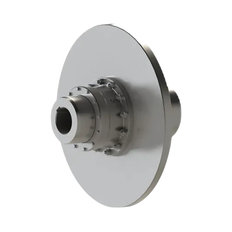
- 16 Product: QGCA type cylindrical shaft hole coupling spherical roller coupling (Q/YJ 16030X-2018)
Modern heavy industrial machinery demands coupling technology that can transmit substantial torque while tolerating shock loads, frequent starting and stopping, installation errors, and structural deformation. In applications such as metallurgy, mining, lifting, port handling, water equipment, paper production, and other continuous-duty industries, a coupling is not simply a connection between two shafts. It is a critical mechanical component that influences equipment availability, gearbox life, vibration levels, maintenance intervals, and overall production efficiency.
The QGCA type cylindrical bore spherical roller coupling, manufactured according to the Q/YJ 16030X-2018 standard, is designed for these demanding conditions. Its cylindrical shaft bore simplifies machining and assembly, while its spherical roller construction provides high torque capacity, radial load resistance, and automatic compensation for angular displacement. The result is a compact, robust, and service-oriented coupling for heavy machinery where conventional rigid connections or ordinary flexible couplings may not provide sufficient operating tolerance.
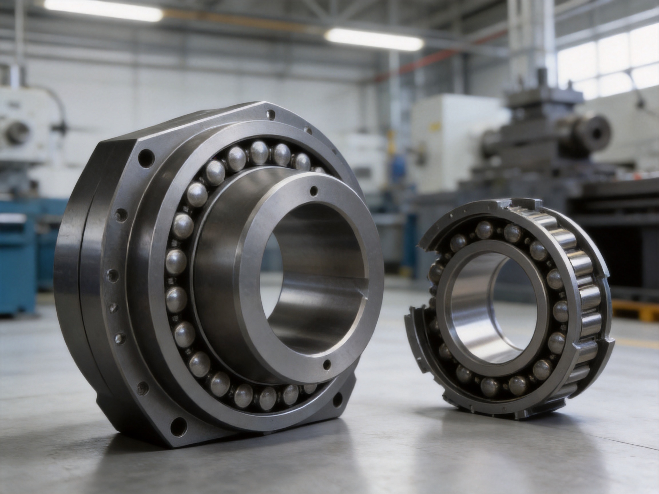
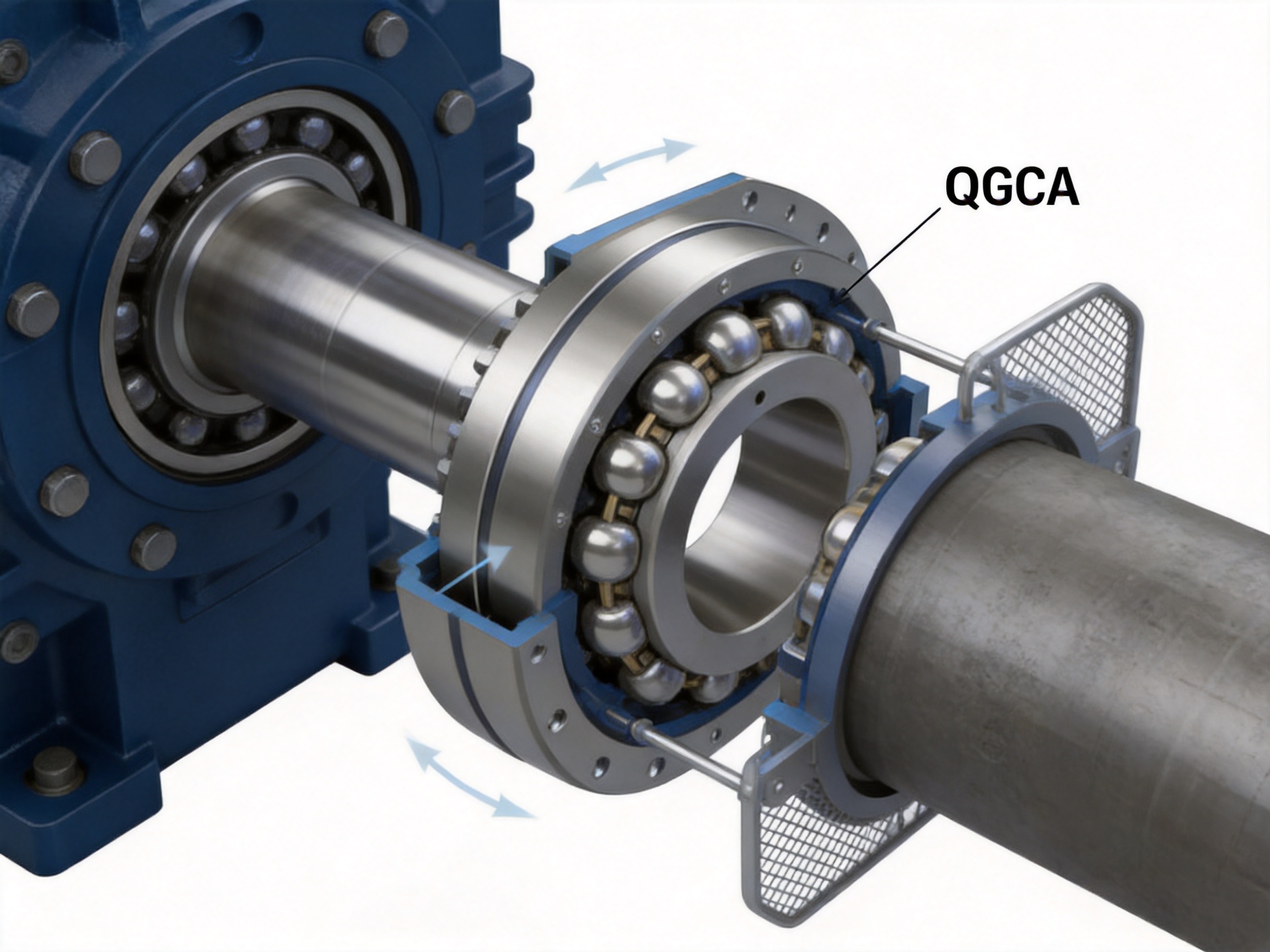
Unlike couplings that depend primarily on rubber, plastic, or thin metallic membranes for flexibility, the QGCA design uses spherical contact between rollers and the coupling bore. This arrangement combines the load-carrying strength of a mechanical coupling with the alignment behavior of a self-aligning bearing. It can accommodate angular displacement of up to approximately 1.5 degrees, helping reduce additional bending moments on reducer output shafts and connected machine shafts.
The product family covers a broad range of sizes, with nominal torque ratings listed from 5 kN·m to 710 kN·m in the main dimensional schedule. The product description also identifies a broader application range extending from approximately 4 kN·m to 900 kN·m, depending on the specific configuration and engineering requirements. Permissible radial force values in the schedule extend from 16.5 kN to 450 kN, while the stated maximum allowable radial force for the product family reaches approximately 520 kN under suitable design conditions.
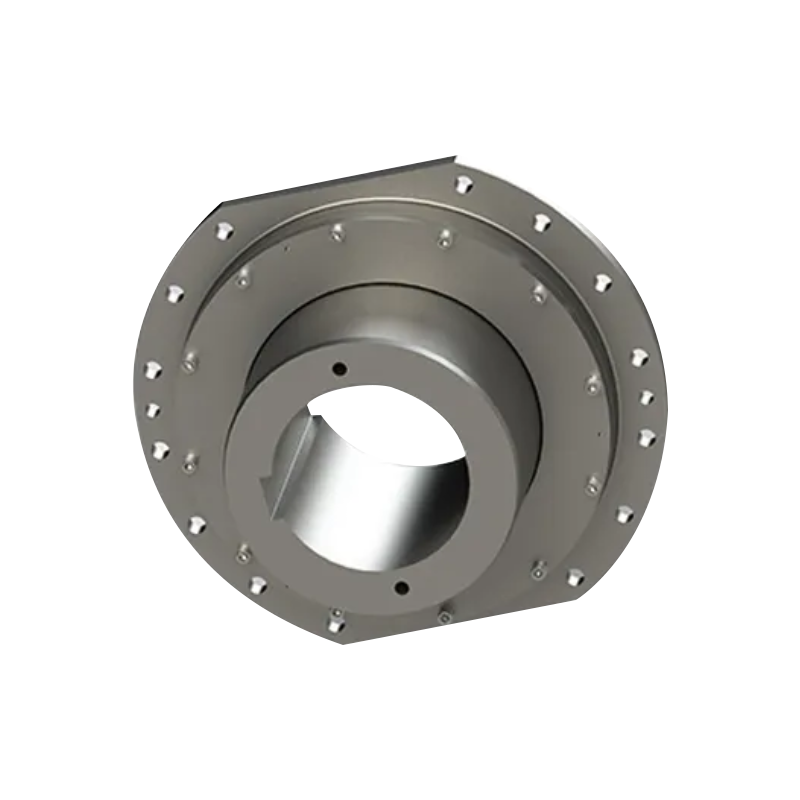
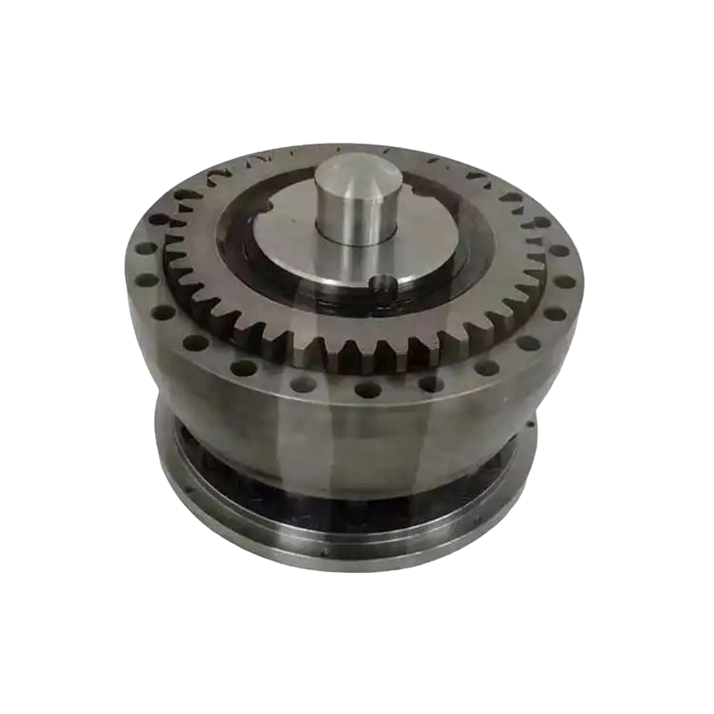
QGCA type cylindrical shaft hole coupling spherical roller coupling (Q/YJ 16030X-2018)
1. Product Overview and Operating Purpose
A coupling transmits rotational power from one shaft to another. In a typical industrial drive, the motor, reducer, drum, roll, pump, conveyor, fan, or other driven machine may not remain perfectly aligned during operation. Manufacturing tolerances, foundation settlement, thermal expansion, shaft deflection, bearing clearance, and frame deformation can all create relative movement between the connected shafts.
A rigid coupling can transmit torque efficiently when the shafts are precisely aligned, but it transfers misalignment forces directly into the bearings and shafts. A conventional flexible coupling can provide some compensation, but its performance may be limited by elastomer aging, fatigue of thin membranes, insufficient radial load capacity, or sensitivity to shock loading. The QGCA spherical roller coupling addresses these problems through a mechanically supported rolling-contact structure.
The coupling consists principally of coupling bodies, spherical rollers, cylindrical shaft bores, and associated retaining and wear-monitoring features. The spherical rollers create a controlled contact interface that allows relative angular movement while continuing to transmit torque. Because the load is distributed through multiple mechanical contact points, the coupling can sustain high loads without depending on a soft elastic insert as its primary torque-transmitting element.
The cylindrical bore is another important characteristic. Instead of requiring complex tapered or specially profiled shaft connections, the cylindrical shaft hole can be machined and matched to standard shaft diameters. This simplifies shaft preparation, reduces manufacturing complexity, and can make replacement or field installation more convenient. Where a required shaft diameter or shaft-hole length falls outside the standard schedule, the dimensions may be agreed with the manufacturer as part of a customized engineering solution.
The QGCA type is classified as a flexible coupling with non-elastic elements. Its flexibility does not come from a rubber block or a metal diaphragm. Instead, it comes from the relative movement permitted by the spherical roller contact geometry. This makes it particularly attractive for high-load applications where non-elastic mechanical flexibility, compact construction, and strong resistance to impact are required together.
2. Key Technical Characteristics
2.1 High Torque Transmission Capacity
The primary purpose of the QGCA coupling is to transmit large rotational torque reliably. The standard size range includes models from QGCA1 through QGCA16. Nominal torque values begin at 5 kN·m for QGCA1 and increase through 7.1, 9, 14, 18, 22.4, 28, 35.5, 50, 100, 160, 224, 355, 500, 630, and 710 kN·m for progressively larger models.
This range allows designers to select a coupling according to the actual torque requirement instead of using a small coupling near its operating limit or an unnecessarily large coupling that increases weight and installation cost. For heavy machinery, correct torque selection is especially important because start-up torque, emergency stopping, reversing, material jams, and cyclic impact can produce loads substantially higher than the normal running torque.
The coupling should be selected using the complete operating load profile. Continuous torque, peak torque, start-stop frequency, shock factor, speed, radial load, angular displacement, shaft diameter, and ambient conditions should all be evaluated. A coupling operating near its nominal rating in a smooth, steady application may require a different size from one operating at the same average torque in a cyclic or impact-loaded system.
2.2 Strong Radial Load Capability
Many industrial couplings transmit torque but are not designed to support a major radial force. The QGCA spherical roller structure is different because its design specifically accommodates substantial radial loading. The standard data table lists permissible radial forces from 16.5 kN for QGCA1 to 450 kN for QGCA16. The general product information identifies a maximum allowable radial force of approximately 520 kN for suitable configurations.
This characteristic is valuable in machines where the coupling is exposed to belt tension, drum loading, roll forces, gear reaction forces, shaft deflection, or other external radial effects. High radial capacity can help reduce the need for additional support arrangements, although the final bearing and shaft system must always be checked as a complete assembly.
Radial load capacity does not mean that the coupling can replace all shaft bearings or that unlimited external forces are acceptable. The permissible value depends on speed, direction of force, load duration, alignment, lubrication, shaft design, and operating temperature. Engineers should confirm the allowable load for the selected model and application before final approval.
2.3 Angular Misalignment Compensation
The spherical contact arrangement enables automatic compensation of angular displacement up to approximately 1.5 degrees. This capability helps accommodate installation errors, shaft angular deviation, foundation movement, frame deformation, and changes caused by operating loads.
Misalignment compensation is particularly important between a reducer and a large driven machine. If the coupling is unable to accommodate angular movement, the reducer output shaft may experience an additional bending moment. Over time, this can increase bearing loads, cause shaft fatigue, accelerate seal wear, and create vibration. By behaving in a manner similar to a self-aligning bearing, the QGCA design helps reduce these secondary forces.
Misalignment capacity should not be treated as permission to ignore alignment procedures. Correct initial alignment remains essential. The compensation feature is intended to absorb practical operating deviations and unavoidable structural movement, not to correct severe installation errors. Proper shaft positioning, foundation preparation, runout inspection, and coupling installation are still required for long service life.
2.4 Compact Structure
Space is often limited in heavy machinery. A coupling may be installed inside a drum assembly, near a gearbox, between machine frames, or in a guarded area where access is restricted. The QGCA coupling uses a compact mechanical arrangement that provides high load capacity without requiring an excessively long installation envelope.
The dimensional schedule includes overall lengths ranging from 84 mm for the smaller models to 450 mm for the largest listed model. Outside diameters increase from 250 mm to 850 mm across the standard range. These dimensions enable engineers to match the coupling to the available machine space while considering shaft extension, guard clearance, bolt access, and maintenance requirements.
A compact coupling can reduce the size of surrounding guards and support structures. It can also help shorten the distance between bearings or connected equipment, which may improve shaft stability. The final installation must still allow sufficient clearance for inspection, lubrication if applicable, wear-indicator reading, fastener maintenance, and safe removal.
2.5 Smooth and Quiet Operation
Spherical rolling contact can support smooth relative movement between the connected members. When the coupling is correctly selected, aligned, assembled, and maintained, the rolling contact design can reduce abrupt sliding friction and contribute to stable operating behavior.
Lower mechanical disturbance benefits equipment in several ways. Reduced vibration can improve the operating environment around the machine, limit stress on connected components, and support more consistent performance. Smooth operation is especially useful in production lines where excessive vibration may affect rolls, drums, pumps, conveyors, or precision process equipment.
Actual noise and vibration depend on many factors beyond the coupling itself. Shaft balance, bearing condition, gear mesh, foundation stiffness, lubrication, load variation, and machine resonance must also be considered. The QGCA coupling is an important part of the vibration-control strategy, but it cannot compensate for defects elsewhere in the drive train.
3. Advantages Compared with Conventional Coupling Designs
3.1 Compared with Rigid Couplings
Rigid couplings are simple and efficient when two shafts remain precisely coaxial under all operating conditions. Their limitation is that they do not absorb angular displacement or meaningful structural movement. Any misalignment is transferred directly into shafts, bearings, and machine housings.
The QGCA spherical roller coupling retains a mechanically strong torque path while allowing controlled angular movement. This gives it an important advantage in machines where alignment changes during operation. The coupling can reduce the mechanical penalty caused by frame deformation and shaft deflection, helping protect the connected equipment from excessive bending loads.
3.2 Compared with Gear Couplings
Gear couplings are widely used for high-torque transmission and can accommodate certain types of misalignment. However, they generally rely on gear tooth engagement and require careful lubrication and inspection. Tooth wear, backlash, lubrication contamination, and installation conditions can affect their service performance.
The QGCA product information indicates approximately 30 percent performance improvement compared with traditional gear couplings in the relevant operating context. This improvement should be interpreted as an application-dependent product claim rather than a universal value for every machine. In suitable heavy-duty installations, the spherical roller design can provide advantages in load bearing, alignment behavior, compactness, and operating stability.
Unlike a gear coupling, the QGCA coupling does not depend on meshing gear teeth to accommodate angular movement. Its spherical roller contact can act more like a self-aligning mechanical support. This may reduce additional bending moment on the reducer output shaft and help avoid some of the stress concentration associated with rigidly constrained gear-coupling arrangements.
3.3 Compared with Elastomeric Couplings
Elastomeric couplings use rubber or polymer elements to provide flexibility and vibration damping. They can be effective in light and medium-duty applications, but their performance can be influenced by temperature, oil exposure, ultraviolet radiation, aging, compression set, and fatigue. They may also have limits in high radial load and severe impact applications.
The QGCA coupling does not depend on a non-metallic elastic insert as the main load-bearing component. Its mechanical roller arrangement is suited to higher loads and frequent start-stop operation. This makes it a strong candidate for M3-M8 operating ranges and other demanding service conditions where impact resistance is more important than soft torsional damping.
Elastomeric couplings may still be preferable when significant torsional vibration isolation is required, when the torque is moderate, or when simple replacement of a flexible element is a priority. Product selection should be based on the complete operating requirement rather than on torque alone.
3.4 Compared with Diaphragm and Membrane Couplings
Diaphragm couplings are valued for their high-speed capability, low backlash, and ability to accommodate certain axial and angular movements. However, the flexible membranes can be sensitive to excessive misalignment, installation damage, cyclic fatigue, and unexpected axial or radial loads.
The QGCA spherical roller coupling is designed for a different duty profile. It prioritizes heavy torque, radial load resistance, shock tolerance, and robust mechanical compensation. It is therefore particularly suitable for large, slower-speed industrial drives where ruggedness and load capacity are more important than extremely low inertia or high-speed precision.
3.5 Compared with Other Roller-Based Couplings
In comparison with simpler roller arrangements, the spherical geometry of the QGCA design is significant. Spherical contact helps the coupling accommodate angular displacement while maintaining a broad and controlled load path. The coupling can therefore combine flexibility with high radial support capacity.
The inclusion of a built-in wear indicator is another practical advantage. Instead of relying only on vibration, noise, temperature, or unexpected clearance to identify wear, maintenance personnel can use the wear scale as a visual condition-monitoring reference. This supports planned maintenance and can reduce the risk of continued operation after the coupling has reached an unacceptable wear condition.
4. Performance in Severe Operating Conditions
Heavy machinery often experiences an operating profile that is more severe than its average power rating suggests. Conveyors may start under load, rolling equipment may encounter uneven material, lifting systems may reverse direction, and metallurgical equipment may be affected by thermal expansion and repeated shock. These conditions create transient loads that can shorten the life of an inadequately selected coupling.
The QGCA coupling is intended for severe impacts and frequent start-stop conditions within M3-M8 operating ranges. Its high mechanical strength and spherical roller construction enable it to manage changing loads without depending on a flexible polymer element that may fatigue or harden over time.
For cyclic machinery, engineers should calculate the equivalent operating torque and consider acceleration torque, braking torque, reverse torque, emergency stopping, and jam conditions. The coupling should also be checked for the number of starts per hour and the duration of each load cycle. A coupling that is suitable for continuous rotation may require a larger size in a reversing or impact-driven installation.
Temperature is also an important factor. Hot metallurgical equipment, outdoor machinery, cold-region installations, and equipment exposed to water or corrosive dust may require specific materials, seals, coatings, lubrication, or inspection intervals. Customized configurations can be discussed when the standard data does not fully represent the operating environment.
5. Main Dimensions and Selection Data
The following table summarizes representative data from the standard dimensional schedule. The entries show the principal model, nominal torque, permissible radial force, standard bore range, overall length, and outside diameter. Some models have multiple bore and length combinations, which are shown in the source data through additional shaft-size rows.
| Model | Nominal Torque Tn (kN·m) | Permissible Radial Force (kN) | Standard Bore d (mm) | Length L (mm) | Outside Diameter D (mm) | Approximate Mass (kg) |
|---|---|---|---|---|---|---|
| QGCA1 | 5 | 16.5 | 40, 42, 45, 48, 50, 55 | 84 | 250 | 12.8 |
| QGCA2 | 7.1 | 18.5 | 45, 48, 50, 55, 60 | 84 | 280 | 16.1 |
| QGCA3 | 9 | 20 | 48, 50, 55, 60, 65 | 84 | 320 | 21.9 |
| QGCA4 | 14 | 25 | 60, 65, 70, 75, 80, 85 | 107 to 132 | 340 | 29.8 |
| QGCA5 | 18 | 35 | 70, 75, 80, 85, 90, 95 | 107 to 132 | 360 | 35 |
| QGCA6 | 22.4 | 38.5 | 80, 85, 90, 95, 100, 110 | 132 to 167 | 380 | 43.3 |
| QGCA7 | 28 | 42 | 85, 90, 95, 100, 110, 120 | 132 to 167 | 400 | 53 |
| QGCA8 | 35.5 | 49 | 100, 110, 120, 130, 140 | 167 to 202 | 420 | 69 |
| QGCA9 | 50 | 70 | 100, 110, 120, 130, 140, 150 | 167 to 202 | 450 | 89 |
| QGCA10 | 100 | 120 | 130, 140, 150, 160, 170, 180 | 202 to 242 | 550 | 156 |
| QGCA11 | 160 | 140 | 160, 170, 180, 190, 200 | 242 to 282 | 580 | 184 |
| QGCA12 | 224 | 170 | 190, 200, 220, 240, 250 | 282 to 330 | 650 | 267 |
| QGCA13 | 355 | 300 | 200, 220, 240, 250, 260 | 282 to 330 | 680 | 319 |
| QGCA14 | 500 | 340 | 240, 250, 260, 280, 300 | 330 to 380 | 710 | 403 |
| QGCA15 | 630 | 380 | 240, 250, 260, 280, 300, 320 | 330 to 380 | 780 | 544 |
| QGCA16 | 710 | 450 | 280, 300, 320, 340, 360, 390 | 380 to 450 | 850 | 693 |
The dimensional values in the table should be used for preliminary selection and layout planning. The actual coupling configuration may include different bore and length combinations, and the final product should be confirmed against the current technical drawing and quotation. Moment of inertia and mass are approximate values calculated according to the minimum shaft-hole diameter in the relevant model range.
6. Shaft Bore and Installation Flexibility
The cylindrical bore is one of the most practical features of the QGCA coupling. Shaft preparation can be based on a cylindrical diameter with the specified H7 bore tolerance. This arrangement is familiar to machine shops and can reduce the complexity associated with special shaft profiles.
During design, the engineer should verify the shaft diameter, shaft extension, keyway or connection method, available shaft-hole length, axial position, and required interference or clearance conditions. The shaft should have adequate strength to withstand transmitted torque, bending load, and stress concentration at the keyway or other connection feature.
Installation requires careful control of cleanliness and dimensional accuracy. Dirt, burrs, raised metal, paint, or impact damage on the shaft or bore can prevent proper seating. Contact surfaces should be checked before assembly, and fasteners should be tightened according to the approved installation procedure. Improper tightening can cause loosening, uneven loading, or damage to the coupling body.
Although the coupling can compensate for angular movement, the connected shafts should be positioned as accurately as possible. The initial alignment should be checked in both angular and parallel directions. The foundation, bearing supports, reducer, and driven equipment should be inspected for soft foot, looseness, or movement before commissioning.
A suitable guard should be installed around the rotating coupling. The guard must provide protection from rotating parts while allowing the wear indicator and inspection points to remain accessible where practical. Guards should not apply external pressure to the coupling or interfere with its permitted movement.
7. Wear Monitoring and Maintenance
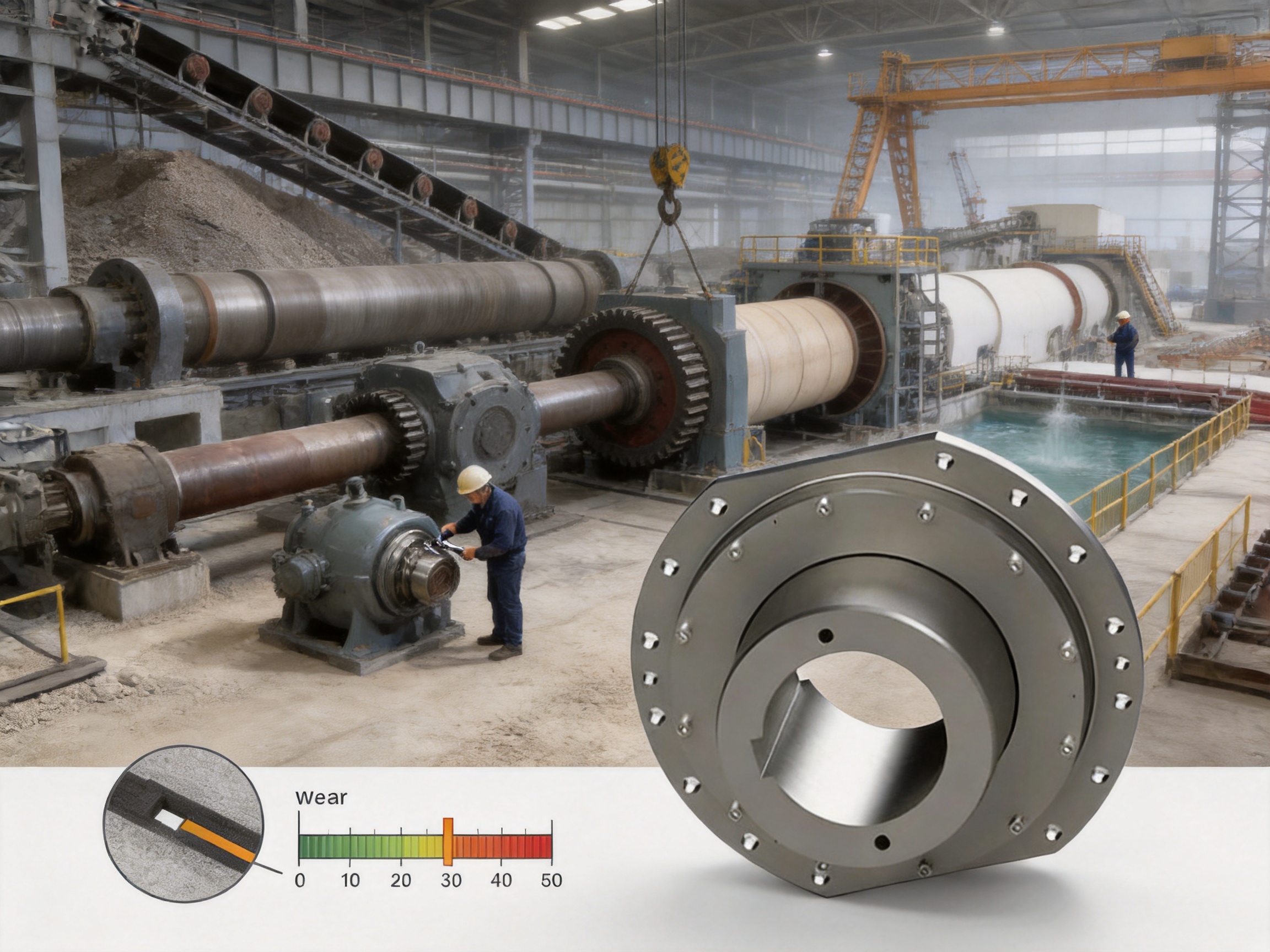
Maintenance efficiency is a major consideration in heavy industry. Unexpected coupling failure can stop an entire production line and may cause secondary damage to shafts, bearings, reducers, and machine structures. The QGCA coupling includes a built-in wear indicator or wear scale to support condition monitoring.
The wear indicator allows maintenance personnel to observe the condition of the coupling against a defined reference. A planned inspection program should record the initial position, operating hours, load conditions, and observed changes. The inspection interval should be adjusted according to speed, radial load, shock level, contamination, and production importance.
Regular inspections should include visual examination of the coupling body, fasteners, bore areas, roller-related surfaces, seals or protective parts, and surrounding guard. Unusual noise, increasing vibration, temperature rise, metallic debris, looseness, or a change in wear-indicator position should be investigated promptly.
Maintenance personnel should never rely on the wear scale alone. The indicator is one part of a broader maintenance program that may include vibration monitoring, thermal inspection, torque checks, shaft alignment verification, lubricant inspection where applicable, and review of operating history.
When maintenance is required, the machine must be isolated, locked out, and prevented from restarting. Stored energy in the drive train must be released or controlled. Heavy QGCA models have substantial mass, with the largest listed model weighing approximately 693 kg. Appropriate lifting equipment and lifting points are therefore essential during removal and installation.
8. Manufacturing Strengths and Engineering Capability
The manufacturer integrates research and development, manufacturing, sales, and technical service. This integrated structure supports a complete product-development process from application analysis and design through machining, assembly, testing, delivery, and after-sales support.
The company operates a new workshop with a total area of approximately 16,463.52 square meters. The facility includes a heavy workshop of about 5,500 square meters, a precision workshop of about 4,600 square meters, an office building and gymnasium of about 2,000 square meters, a dining hall of approximately 500 square meters, a warehouse of approximately 1,000 square meters, and additional roads, landscaping, and parking areas.
The division between heavy and precision workshop areas is valuable for coupling production. Large coupling bodies require sufficient lifting capacity, machining space, and handling equipment, while bore finishing, dimensional inspection, and contact-surface preparation require controlled precision processes. Separating these activities can improve workflow and help maintain production efficiency across both large and small coupling models.
8.1 Research and Development
Research and development capability is essential for spherical roller couplings because performance depends on contact geometry, material selection, stress distribution, roller movement, clearance, manufacturing tolerance, and lubrication or protection strategy. Engineering teams must understand not only the nominal torque but also the behavior of the coupling under radial load, angular displacement, shock, and repeated cycling.
The company provides standard product specifications as well as non-standard coupling design. This enables technical evaluation when a customer requires a special shaft diameter, unusual shaft-hole length, modified installation dimensions, special material, different protective arrangement, or a coupling adapted to a particular machine layout.
8.2 Heavy Machining and Precision Manufacturing
Large coupling components require robust machining equipment capable of processing heavy steel parts while maintaining dimensional stability. The main bore, outside diameters, bolt circles, roller contact surfaces, and locating features must be manufactured according to the approved drawing.
Precision machining is particularly important for the cylindrical shaft bore. The stated H7 bore designation indicates a controlled dimensional tolerance. Accurate bore production improves fit, reduces unwanted movement, and supports more predictable torque transmission. It also helps ensure that the coupling can be installed without excessive force or uneven contact.
Contact surfaces must be manufactured and finished consistently. Variations in geometry or roughness can influence load distribution, friction, wear, and noise. The production process should therefore include appropriate turning, boring, milling, drilling, finishing, cleaning, and inspection operations according to the component and material requirements.
8.3 Quality Control and Testing
Reliable coupling production requires quality control at multiple stages. Incoming material inspection verifies that raw materials meet the required grade and condition. In-process inspection checks critical dimensions during machining, while final inspection verifies the completed assembly against the technical drawing and quality requirements.
Important inspection points may include bore diameter, bore roundness, shaft-hole length, outside diameter, overall length, bolt-hole position, roller dimensions, contact condition, concentricity, runout, surface quality, and assembly clearance. Heavy-duty couplings should also be evaluated for correct rotation, abnormal interference, and proper operation of the wear indicator.
The company identifies advanced testing facilities, strict quality control, reliable production guarantees, and compliance with international standards and certifications such as ISO 9001 as part of its manufacturing strengths. These systems help establish repeatable production procedures and provide customers with greater confidence in product consistency.
8.4 Customization and Non-Standard Design
Standardization improves availability and cost control, but industrial machinery frequently includes non-standard shafts, unusual mounting distances, restricted installation spaces, or special process conditions. The ability to design and manufacture customized couplings is therefore an important supplier advantage.
Customization may involve changing the cylindrical bore diameter, extending or shortening the shaft-hole length, modifying the external dimensions, adapting the mounting interface, selecting materials for a special environment, or developing a coupling for a unique load and speed combination.
A responsible custom design process begins with complete application information. The supplier should receive motor power, operating speed, nominal and peak torque, shaft dimensions, radial force, angular displacement, start-stop frequency, ambient temperature, dust or moisture conditions, installation space, and required service life. Accurate information improves the quality of the engineering recommendation and avoids selecting a coupling based only on nominal power.
9. Industrial Applications
9.1 Metallurgical Equipment
Metallurgical machinery often operates under high temperatures, heavy loads, frequent starts, and substantial shock. Rolling mills, transfer equipment, cooling systems, material-handling mechanisms, and other steel-production machinery can benefit from a coupling that tolerates shaft movement and high radial loads.
The QGCA coupling can help protect reducer output shafts where roll or drum forces create additional bending. Its compact layout is also useful where the drive must fit between machine frames or inside a restricted guard.
9.2 Mining Equipment
Mining equipment is exposed to dust, impact, uneven material flow, and demanding duty cycles. Crushers, conveyors, feeders, screens, winches, and material-transfer systems may all produce fluctuating torque and radial forces.
The robust mechanical construction and broad torque range make the QGCA family suitable for evaluating in these applications. Environmental protection, sealing, maintenance access, and material selection should be considered carefully in dusty or abrasive locations.
9.3 Lifting and Port Equipment
Cranes, hoists, winches, ship loaders, unloaders, and port conveyors often require controlled starting, stopping, reversing, and braking. These movements can generate transient torque that is considerably higher than steady operating torque.
The coupling should be selected with the complete acceleration and braking profile in mind. Its capacity to accommodate angular movement can help manage structural deflection in large frames, while its radial load capability can be relevant to drums and shaft-supported lifting mechanisms.
9.4 Water Equipment
Pumps, mixers, sluice mechanisms, water-treatment equipment, and large fluid-handling systems may operate continuously for long periods. A compact coupling with stable operation and controlled misalignment compensation can support reliable power transmission in these installations.
Where water, humidity, chemicals, or outdoor exposure are present, the coupling specification should include suitable corrosion protection, sealing, and maintenance procedures. The coupling should also be evaluated for the starting characteristics of the pump and the possibility of hydraulic transients.
9.5 Paper and Process Equipment
Paper machinery often combines continuous operation with strict requirements for vibration control and production availability. Roll drives, winding systems, conveyors, and auxiliary equipment may benefit from smooth torque transmission and reduced additional shaft bending.
Correct balancing, alignment, and speed verification remain essential. Where high rotational speed or very low torsional stiffness is required, the QGCA design should be compared with other coupling types before final selection.
10. Coupling Selection Method
The first step is to determine the transmitted torque. If motor power and speed are known, nominal torque can be estimated using the appropriate power-speed relationship. The result should then be adjusted for service factor, shock, starts per hour, reversing operation, braking, and other transient conditions.
The second step is to verify radial force. Radial force may come from the driven machine, drum or roll weight, belt tension, gear reaction, shaft deflection, or external structural loading. The selected model must have a permissible radial force greater than the calculated operating requirement with a suitable safety margin.
The third step is to check angular displacement and any parallel or axial movement. The QGCA coupling offers angular compensation of approximately 1.5 degrees, but the engineer should confirm whether the application includes other types of movement that require an additional coupling feature or a different design.
The fourth step is to match the shaft bore. The standard cylindrical bore range should be compared with the actual shaft diameter and shaft-hole length. If the shaft dimensions fall outside the listed range, a customized design can be considered.
The fifth step is to review the installation envelope. Overall length, outside diameter, bolt access, guard clearance, lifting access, and inspection space should all be confirmed. The mass of larger models must be considered when selecting lifting equipment and support structures.
The final step is to review the operating environment and maintenance plan. Temperature, contamination, moisture, corrosion, speed, lubrication, inspection frequency, spare-parts policy, and expected service life should be included in the technical review.
11. Installation and Commissioning Recommendations
Before installation, verify that the delivered model, bore, length, and accessories match the approved order and drawing. Inspect all surfaces for transport damage. Confirm that the shaft, coupling bore, key, fasteners, and adjacent components are clean and free from burrs or foreign material.
Check shaft alignment before fitting the coupling. Correct soft foot, loose foundations, damaged bearings, or incorrect reducer positioning before final assembly. The coupling should not be used to force two badly misaligned shafts into position.
Install the coupling using appropriate tools. Avoid striking precision surfaces with an uncontrolled hammer. Use suitable lifting equipment for large models, and support the coupling so that its weight does not overload the shaft or bearing during assembly.
After assembly, rotate the shaft manually where possible to confirm that there is no binding or abnormal interference. Verify fastener tightening, guard clearance, wear-indicator visibility, and the correct location of any lubrication or inspection points.
During initial commissioning, operate at low load if the machine design permits. Observe vibration, noise, temperature, and general behavior. Gradually increase the load while checking for abnormal conditions. Record the initial wear-indicator position and commissioning data as a reference for future maintenance.
12. Q&A
Q1: What type of coupling is the QGCA product?
The QGCA is a flexible coupling with non-elastic elements. It uses spherical rollers and mechanical contact geometry to provide flexibility rather than relying on rubber, plastic, or a metal diaphragm as the primary flexible element.
Q2: What does the cylindrical bore mean?
A cylindrical bore means that the shaft hole is manufactured as a cylindrical opening, with standard bore sizes identified in the dimensional schedule. This simplifies shaft machining and can make installation and replacement more straightforward than designs requiring special tapered or profiled shaft connections.
Q3: How much angular misalignment can the coupling compensate for?
The product information identifies automatic angular displacement compensation of up to approximately 1.5 degrees. The actual allowable value should be confirmed for the selected model and operating condition. Initial shaft alignment should still be performed carefully.
Q4: What is the nominal torque range?
The listed standard schedule covers nominal torque from 5 kN·m for QGCA1 to 710 kN·m for QGCA16. The broader product description identifies an application range of approximately 4 kN·m to 900 kN·m, depending on the configuration and engineering requirements.
Q5: What is the maximum radial force?
The standard table lists permissible radial force values from 16.5 kN to 450 kN. The general product information states a maximum allowable radial force of approximately 520 kN for suitable product configurations. Final selection should be based on the approved technical specification.
Q6: Is the QGCA coupling suitable for frequent starting and stopping?
Yes. The coupling is intended for severe impact and frequent start-stop conditions in M3-M8 operating ranges. The selection must include starting torque, braking torque, reversing conditions, shock factors, and the number of operating cycles.
Q7: How does it compare with a gear coupling?
The spherical roller design provides a different method of accommodating angular movement and radial loading. It can act similarly to a self-aligning bearing and may reduce additional bending moment on a reducer output shaft. The product information indicates approximately 30 percent performance improvement over traditional gear couplings in the relevant application context, but actual results depend on system conditions.
Q8: Does the coupling require accurate alignment?
Yes. Misalignment compensation improves operating tolerance but does not eliminate the need for correct installation. Accurate initial alignment reduces load, wear, vibration, and stress on the connected equipment.
Q9: How is wear monitored?
The coupling includes a built-in wear indicator or wear scale. Maintenance personnel can inspect the indicator and compare its position with the approved service reference. Inspection should also include vibration, temperature, noise, fasteners, contact surfaces, and surrounding components.
Q10: Can the shaft bore be customized?
Yes. If the diameter or length of the cylindrical shaft hole falls outside the standard table, the dimensions can be discussed with the manufacturer. Customization should be based on complete shaft, torque, load, speed, and installation information.
Q11: Which industries can use this coupling?
Potential industries include metallurgy, mining, lifting, ports, water equipment, paper production, conveyors, heavy material handling, and other industrial sectors requiring high torque, radial load resistance, and angular misalignment compensation.
Q12: What information is needed for a technical quotation?
Useful information includes motor power, rotational speed, nominal and peak torque, shaft diameters, shaft-hole lengths, radial force, angular displacement, operating temperature, start-stop frequency, shock conditions, installation dimensions, environmental conditions, and required quantity.
13. Supplier Service and Product Support
Zhongye Heavy Industry Technology integrates coupling research, manufacturing, sales, and service. Its product portfolio includes gear couplings, elastic sleeve pin couplings, elastic pin couplings, universal couplings, tire couplings, jaw couplings, star couplings, diaphragm couplings, drum couplings, grid couplings, Oldham couplings, flange couplings, clip-shell couplings, roller chain couplings, safety couplings, and other customized products.
This broad product range allows the engineering team to compare coupling types according to torque, speed, misalignment, damping, radial force, space, maintenance, and environmental requirements. Such comparison is useful when a customer is not yet certain whether a spherical roller coupling, gear coupling, diaphragm coupling, elastomeric coupling, or another design is the best solution.
The company provides pre-sale technical support, non-standard design solutions, manufacturing support, quality control, and after-sale service. For large industrial couplings, these services are important because the product is normally part of a larger mechanical system and cannot be selected independently from the reducer, shaft, bearing, foundation, and driven machine.
The company is located in Zhenjiang, Jiangsu Province, China, and serves customers in multiple industrial fields. Its stated strengths include complete specifications, customization support, advanced testing facilities, high transmission efficiency, quality management, and technical experience in coupling applications.
14. Conclusion
The QGCA cylindrical bore spherical roller coupling is a heavy-duty mechanical coupling developed for demanding industrial transmission systems. Its combination of cylindrical shaft-bore convenience, spherical roller contact, high torque capacity, strong radial load capability, compact construction, smooth operation, and angular misalignment compensation makes it a practical solution for severe service conditions.
Its most important advantage is the way it combines flexibility with mechanical load support. The spherical roller arrangement can accommodate angular movement while helping reduce additional bending forces on reducer output shafts and connected machine components. This is particularly valuable in large machinery affected by installation tolerances, structural deformation, shaft deflection, and repeated impact.
The broad QGCA1-QGCA16 range gives engineers multiple options for matching torque, radial force, shaft diameter, installation space, and machine scale. The built-in wear indicator supports planned maintenance, while the cylindrical bore simplifies manufacturing and assembly. For applications outside the standard dimensional range, customized shaft-hole dimensions and non-standard coupling designs can be evaluated.
Reliable performance depends on correct selection, accurate alignment, appropriate installation, regular inspection, and proper operating control. When these requirements are addressed, the QGCA coupling can provide a durable connection for metallurgical equipment, mining machinery, lifting systems, port equipment, water machinery, paper equipment, conveyors, and other heavy industrial applications.
References
Q/YJ 16030X-2018, Technical Standard for QGCA Cylindrical Bore Spherical Roller Couplings.
QGCA Cylindrical Shaft-Hole Spherical Roller Coupling Product Data and Main Dimension Schedule.
ISO 9001, Quality Management Systems: Requirements.
Industrial Coupling Selection and Application Engineering Principles.
Mechanical Power Transmission Design Guidelines for Flexible Couplings.
Industrial Shaft Alignment, Maintenance, and Condition-Monitoring Practices.
Product: QGCA type cylindrical shaft hole coupling spherical roller coupling (Q/YJ 16030X-2018)

- Quick Links
- About
- Products
- Our Service
- News & Events
- Contact
- Products Series
- Flexible Couplings with Non-Elastic Elements
- Flexible Couplings with Metal Elastic Elements
- Flexible Couplings with Non-Metallic Elastic Elements
- Safety Coupling
- Rigid Coupling
- Contact Us
- Tel : +86 511 8572 3800 +86 511 8572 3900
- Mobile : +86 15106109009
- Email : sales@couplingzy.com
- Add:No.1 Zhongye Yingbin Avenue, Gaozi Street, Dantu Economic Development Zone, Zhenjiang City, Jiangsu Province, China.


