:+86 15106109009
:sales@couplingzy.com


 English
 русский
 Español
 عربى
 Português
 Deutsch
 Türk
 Indonesia


Heavy-Duty Drum Gear Coupling with Integrated Brake Wheel for Reliable Industrial Transmission
Content
- 1 Introduction
- 2 Product Construction and Operating Principle
- 3 Main Advantages Compared with Conventional Alternatives
- 4 Technical Range and Representative Parameters
- 5 Manufacturing Process and Engineering Strengths
- 6 Application Industries
- 7 Selection Method
- 8 Installation and Maintenance Recommendations
- 9 Safety Considerations
- 10 Why Choose a Specialized Coupling Manufacturer
- 11 Conclusion
- 12 Questions and Answers
- 12.1 What type of coupling is the GBLZ series?
- 12.2 What does the brake wheel do?
- 12.3 What is the nominal torque range?
- 12.4 What is the maximum allowable speed?
- 12.5 What brake wheel diameters are available?
- 12.6 Can the coupling compensate for poor alignment?
- 12.7 What materials are used?
- 12.8 What is dimension B2?
- 12.9 Which industries use this coupling?
- 12.10 Can customized couplings be produced?
- 12.11 How often should the coupling be lubricated?
- 12.12 Can the brake wheel be used without a guard?
- 13 References
- 14 Product: GBLZ Drum gear coupling with brake wheel (Q/YG 11005X-2018)
Introduction
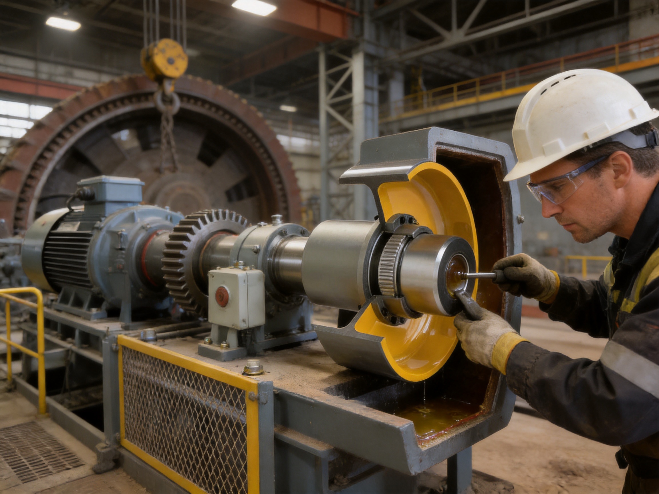
Industrial transmission systems increasingly require more than simple power transfer. Modern metallurgical lines, mining machines, lifting equipment, port machinery, paper plants, and water-treatment systems must transmit high torque, tolerate shaft misalignment, operate reliably under changing loads, and stop safely when required. Combining these functions in a single mechanical assembly can reduce installation space, simplify maintenance, and improve the overall performance of the driven system.
The GBLZ drum gear coupling with brake wheel is designed for precisely this type of demanding service. Manufactured in accordance with Q/YG 11005X-2018, it combines the load-transmitting capability of a gear coupling with the braking interface of an integrated brake wheel. The result is a compact and robust solution for applications requiring both flexible torque transmission and controlled deceleration or stopping.
Unlike a rigid coupling, the GBLZ design accommodates angular, radial, and axial shaft displacement. Unlike many conventional flexible couplings, it also provides a dedicated brake wheel that can work with an appropriate industrial braking system. This integrated construction helps equipment designers reduce the number of separate components around the drive line while maintaining access for inspection, lubrication, seal replacement, and service.
The product range includes GBLZ1 through GBLZ14, covering nominal torque ratings from 0.63 kN·m to 125 kN·m. Depending on the model, allowable speed reaches as high as 4,000 r/min, while larger versions are rated for heavy-duty service at approximately 950 r/min. Brake wheel diameters range from 160 mm to 800 mm, allowing the coupling to be selected for both compact drive systems and large industrial machinery.
This article examines the construction, operating principles, performance advantages, technical range, manufacturing strengths, application value, maintenance requirements, and selection considerations of the GBLZ drum gear coupling with brake wheel.
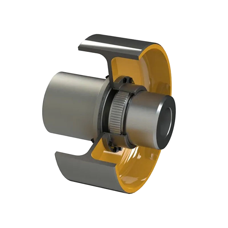
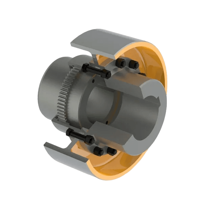
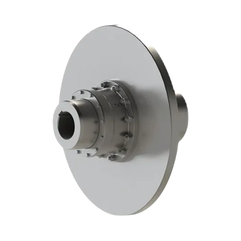
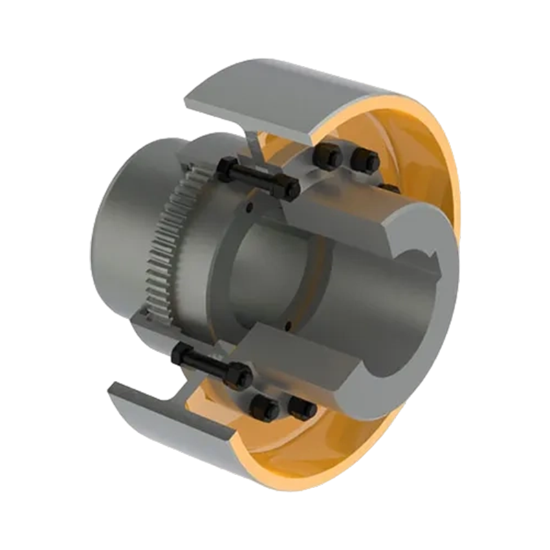
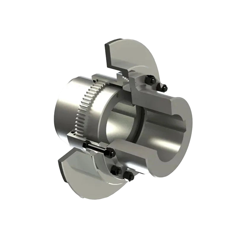
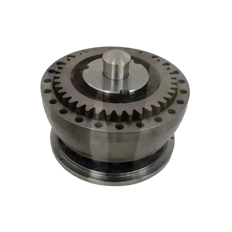
GBLZ Drum gear coupling with brake wheel (Q/YG 11005X-2018)
Product Construction and Operating Principle
The GBLZ coupling is a flexible coupling with non-elastic elements. Its torque-transmitting mechanism is based on external and internal gear engagement rather than rubber, polyurethane, or another elastomeric component. This gear-based arrangement allows the coupling to transmit substantial torque while accommodating controlled shaft misalignment.
The primary components generally include two hubs, internal gear sleeves or gear rings, sealing elements, lubrication spaces, connecting hardware, and an integrated brake wheel. The hubs are mounted on the driving and driven shafts. Their external gear teeth engage with the internal teeth of the surrounding sleeves. As the driving shaft rotates, torque passes through the gear teeth and is transferred to the driven shaft.
The gear teeth are designed to permit limited relative movement between the shafts. When two shafts are not perfectly collinear, the gear engagement remains capable of transmitting torque while allowing the coupling to compensate for angular and radial displacement. Axial movement can also be accommodated within the permitted design range. This flexibility helps prevent excessive secondary loads from being transferred to bearings, gearboxes, motors, and connected equipment.
The brake wheel is integrated into the coupling structure. It provides a cylindrical braking surface for a compatible brake, such as a drum brake or another industrial braking arrangement selected according to the machine design. During operation, the brake wheel rotates with the coupling. When the brake is applied, friction at the wheel surface produces deceleration or stopping torque.
The coupling therefore performs two related functions. First, it forms a mechanical link between two shafts and transmits rotational power. Second, it provides a defined braking interface located directly on the transmission line. This arrangement is particularly useful in hoisting, lifting, conveying, rolling, and other applications where stopping performance is as important as continuous torque transmission.
Gear Transmission
Gear couplings are valued for their high torque density. The gear teeth distribute the transmitted load across a comparatively large contact area, allowing a relatively compact coupling to handle significant torque. The exact permissible torque depends on the selected model, bore size, speed, service conditions, lubrication, alignment, and applicable design factors.
The GBLZ series uses a robust gear structure suited to industrial environments. The tooth engagement transfers torque positively, without depending on the shear strength or compression behavior of an elastic insert. This is an important advantage in applications exposed to high temperatures, heavy loads, frequent starts, or severe operating cycles.
Misalignment Compensation
Perfect alignment is difficult to maintain in real machinery. Foundation settlement, thermal expansion, manufacturing tolerances, bearing wear, shaft deflection, and installation variation can all create alignment errors. A rigid connection transfers these errors directly into the shafts and bearings. A flexible gear coupling provides a degree of mechanical accommodation.
Angular misalignment occurs when the connected shaft centerlines intersect at an angle. Radial misalignment occurs when the centerlines are parallel but offset. Axial displacement occurs when the distance between the connected shafts changes. The GBLZ structure is designed to compensate for these types of displacement within specified limits.
Misalignment compensation does not eliminate the need for proper installation. The coupling must still be aligned according to the manufacturer’s requirements. Operating beyond the permissible displacement range can accelerate tooth wear, increase heat generation, raise vibration, and shorten seal life. Correct alignment remains one of the most important conditions for achieving the expected service life.
Integrated Brake Wheel
The integrated brake wheel distinguishes the GBLZ series from a standard drum gear coupling. Instead of installing a separate brake disc or wheel elsewhere in the drive train, the braking surface is incorporated into the coupling assembly. This can simplify the machine layout and reduce the space required for independent transmission and braking components.
In normal operation, the brake wheel rotates together with the shafts. During controlled stopping, the brake applies a regulated braking force to reduce rotational speed. During an emergency, a suitable braking system can be used to bring the equipment to a rapid stop, subject to the machine’s inertia, load, brake capacity, thermal limits, and safety design.
The brake wheel must not be selected solely by diameter. Brake torque, braking speed, duty cycle, energy absorption, friction material, ambient conditions, and emergency-stop requirements must all be evaluated. The coupling and brake should be treated as a coordinated mechanical system.
Main Advantages Compared with Conventional Alternatives
Combined Transmission and Braking Function
A conventional flexible coupling transmits torque but normally does not provide a braking surface. A separate brake assembly must be positioned elsewhere, often requiring additional brackets, shafts, guards, and alignment work. The GBLZ coupling combines the coupling function and brake wheel function in one engineered assembly.
This integration can reduce the number of separate components, shorten the drive-line layout, and simplify equipment design. It can also make the braking location easier to define because the wheel is mounted directly in the torque path. In space-constrained machinery, this can be a substantial design benefit.
Higher Torque Density than Many Elastomeric Couplings
Elastomeric couplings are effective for vibration damping and moderate misalignment compensation, but their performance can be limited by temperature, aging, chemical exposure, fatigue, and the strength of the elastic element. The GBLZ coupling uses metal gear elements and is therefore suited to higher torque and more severe industrial conditions.
Because the gear teeth carry the principal torque load, the coupling can deliver high torque within a relatively compact envelope. This makes it attractive for heavy equipment where a larger elastic coupling would be required to achieve the same torque capacity.
Resistance to Severe Industrial Conditions
Metallic transmission elements are generally more appropriate than polymeric elements for high-temperature areas, heavy shock loading, oil exposure, dust, and demanding duty cycles. The GBLZ coupling is manufactured from high-grade steel or alloy steel, supporting strength, wear resistance, and long-term structural reliability.
The actual material specification and heat-treatment requirements should be confirmed for each order, particularly when the coupling is used in a high-temperature furnace area, corrosive environment, or high-cycle lifting application. Nevertheless, the metallic construction provides a strong foundation for industrial durability.
Improved Protection for Connected Equipment
Misalignment compensation reduces the tendency of the coupling to impose excessive radial or angular loads on connected equipment. By allowing limited relative movement, the coupling can help protect motor bearings, gearbox bearings, shaft extensions, and other transmission components.
This benefit is especially important in long equipment trains where multiple components may move slightly relative to one another during operation. A flexible coupling can help absorb installation variation and dynamic movement, reducing the risk of premature bearing damage and shaft stress.
Broad Selection Range
The fourteen principal model sizes provide a broad range of torque, speed, bore, and brake wheel options. Small models are available for compact, faster-running machinery, while large models are designed for high-torque, lower-speed industrial equipment.
The range also includes multiple shaft hole combinations for many models. This supports practical matching with motors, reducers, drums, rolls, gearboxes, and other rotating machinery. When a standard bore or dimensional arrangement is not suitable, the manufacturer can also evaluate customized or non-standard designs.
Serviceable Lubricated Design
Gear couplings require effective lubrication to reduce tooth friction, control wear, and dissipate heat. The GBLZ design includes a grease-filled gear chamber and sealing arrangement. Proper lubrication can help preserve tooth surfaces and extend operating life.
The structural arrangement also considers maintenance access. Dimension B2 is specifically identified as the clearance required for seal replacement. This detail is important during equipment layout because adequate service space can reduce maintenance downtime and prevent difficult disassembly work.
Technical Range and Representative Parameters
The following table summarizes representative principal parameters for the GBLZ series. Actual selection must be based on the complete manufacturer’s technical documentation, including bore configuration, shaft hole length, speed, service factor, brake requirements, alignment conditions, and installation arrangement.
| Model | Nominal Torque kN·m | Allowable Speed r/min | Typical Brake Wheel Diameter mm | Maximum Listed Bore mm | Approximate Mass Range kg |
|---|---|---|---|---|---|
| GBLZ1 | 0.63 | 4000 | 160 | 35 | 7.3–8.4 |
| GBLZ2 | 1.0 | 4000 | 160 | 45 | 9.2–10.5 |
| GBLZ3 | 1.6 | 3800 | 200 | 56 | 15.1–18.8 |
| GBLZ4 | 2.8 | 3800 | 200 | 65 | 19.8–26.8 |
| GBLZ5 | 4.5 | 3000 | 250 | 75 | 33.3–39.0 |
| GBLZ6 | 6.3 | 3000 | 250 | 90 | 40.0–53.2 |
| GBLZ7 | 8.0 | 2400 | 315 or 300 | 100 | 51.8–79.6 |
| GBLZ8 | 11.2 | 1900 | 400 | 110 | 84.0–117 |
| GBLZ9 | 18 | 1500 | 500 | 130 | 128–167 |
| GBLZ10 | 25 | 1200 | 630 or 600 | 150 | 184–246 |
| GBLZ11 | 36.1 | 1050 | 710 or 700 | 170 | 240–361 |
| GBLZ12 | 56 | 1050 | 710 or 700 | 200 | 290–470 |
| GBLZ13 | 80 | 950 | 800 | 220 | 488–598 |
| GBLZ14 | 125 | 950 | 800 | 250 | 638–780 |
The table demonstrates the basic design trend: as torque capacity increases, allowable speed generally decreases and the external dimensions, brake wheel size, moment of inertia, and mass increase. This is normal for heavy-duty mechanical transmission equipment. A larger coupling provides greater load capacity, but it also affects shaft loading, installation handling, starting inertia, and braking energy.
The maximum diameter of the tapered shaft hole is specified as 220 mm in the product information. Bore selection must also consider shaft tolerance, keyway dimensions, hub length, mounting method, and the required balance grade for the operating speed.
Brake Wheel Parameters
The brake wheel series includes standard diameters of 160, 200, 250, 315, 400, 500, 630, 710, and 800 mm. The corresponding wheel mass and moment of inertia increase significantly with diameter. For example, the 160 mm wheel has a listed mass of approximately 2.83 kg and a moment of inertia of 0.014 kg·m², while the 800 mm wheel has a listed mass of approximately 203 kg and a moment of inertia of 26.76 kg·m².
| Brake Wheel Diameter mm | T mm | K mm | Mass kg | Moment of Inertia kg·m² |
|---|---|---|---|---|
| 160 | 70 | 6 | 2.83 | 0.014 |
| 200 | 85 | 8 | 5.20 | 0.043 |
| 250 | 105 | 10 | 10.1 | 0.128 |
| 315 | 135 | 12 | 17.2 | 0.354 |
| 400 | 170 | 14 | 33.4 | 1.11 |
| 500 | 210 | 18 | 56.3 | 3.07 |
| 630 | 265 | 22 | 101.3 | 8.55 |
| 710 | 300 | 22 | 145.8 | 15.52 |
| 800 | 340 | 26 | 203.0 | 26.76 |
The brake wheel diameter should be selected together with the brake lining width, allowable surface pressure, braking torque, heat dissipation, and required stopping time. A larger wheel can offer a greater braking radius, but it can also introduce greater rotational inertia and a larger installation envelope.
Manufacturing Process and Engineering Strengths
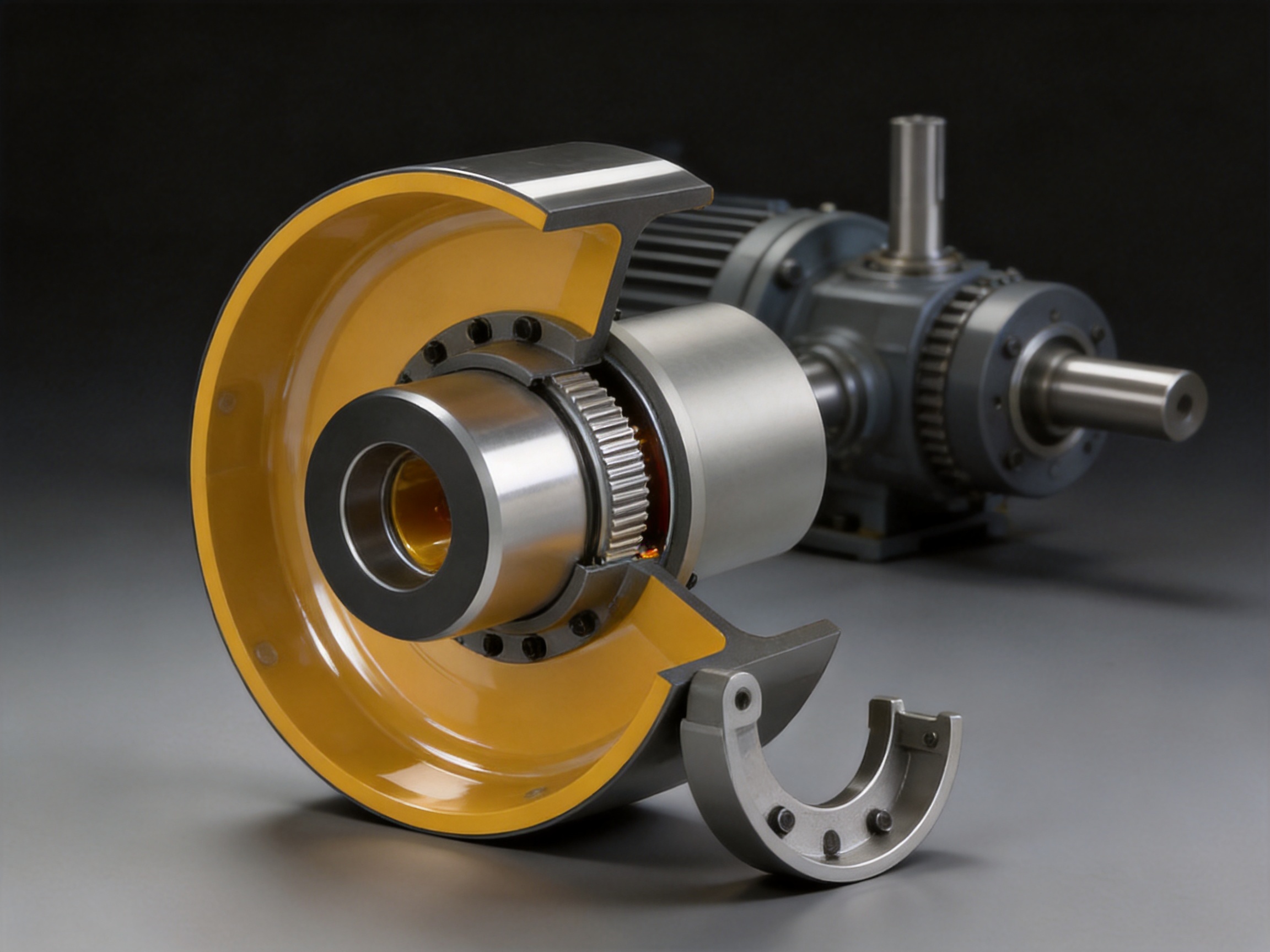
The performance of a heavy-duty coupling depends not only on its nominal dimensions but also on material quality, tooth accuracy, heat treatment, concentricity, surface finish, sealing quality, inspection standards, and assembly control. Zhongye Heavy Industry Technology (Zhenjiang) Co., Ltd. integrates research and development, manufacturing, and sales to support the complete product lifecycle.
Engineering and Product Development
The company maintains experience in the design and manufacture of many coupling categories, including toothed couplings, elastic sleeve pin couplings, elastic pin couplings, universal couplings, tire couplings, jaw couplings, star couplings, diaphragm couplings, drum couplings, grid couplings, Oldham couplings, flange couplings, clip-shell couplings, roller-chain couplings, safety couplings, and customized couplings.
This broad product knowledge is valuable when selecting a GBLZ coupling because the correct solution depends on the entire drive system rather than one isolated component. Engineers can compare gear, diaphragm, pin, grid, tire, safety, or rigid coupling concepts according to torque, misalignment, vibration, braking, speed, environment, and maintenance requirements.
For non-standard projects, the manufacturer can evaluate special bore combinations, dimensional modifications, mounting constraints, brake wheel arrangements, material requirements, and application-specific performance conditions. Such technical support is particularly useful for replacement projects where the original coupling is no longer available or where the available installation space is restricted.
Heavy and Precision Workshop Capability
The company’s new workshop covers approximately 16,463.52 square meters. It includes a heavy workshop of approximately 5,500 square meters, a precision workshop of approximately 4,600 square meters, an office building and gymnasium, a dining facility, a warehouse, and supporting roads and service areas.
The separation of heavy and precision production areas supports the different requirements of large industrial components and accurately machined transmission parts. Heavy equipment can be processed with suitable lifting, handling, and machining resources, while precision work can be controlled in an environment focused on dimensional accuracy and surface quality.
For a drum gear coupling with brake wheel, this manufacturing environment supports the production of large hubs, gear sleeves, brake wheels, shafts, and related components. It also provides practical advantages for handling large workpieces, maintaining organized production flows, and completing inspection before shipment.
Material and Heat-Treatment Control
High-grade steel or alloy steel is used for demanding coupling applications. Material selection must take account of torque, bending stress, tooth contact pressure, impact loading, fatigue, temperature, and environmental exposure. Proper heat treatment can improve the hardness, strength, wear resistance, and fatigue performance of gear teeth and other highly loaded components.
Heat treatment must be carefully controlled because excessive hardness can increase brittleness, while insufficient hardness can accelerate tooth wear and deformation. Dimensional changes caused by heat treatment must also be considered during subsequent machining and inspection.
For industrial customers, traceability of raw material, heat-treatment records, machining inspection, and final assembly is an important part of quality assurance. These controls help confirm that the finished coupling is consistent with the approved design and purchase specification.
Precision Gear Machining
The internal and external gear teeth are central to the coupling’s performance. Tooth profile accuracy, pitch accuracy, runout, backlash, surface finish, and concentricity influence load distribution, noise, vibration, lubrication behavior, and service life.
Precision machining is therefore required to produce the mating gear elements. The process can include turning, gear cutting, heat treatment, finishing, deburring, dimensional inspection, and final cleaning. Particular attention is required at tooth roots, tooth flanks, sealing surfaces, keyways, and mounting faces.
Accurate concentricity between the bore, gear teeth, and brake wheel is also essential. Excessive eccentricity can create vibration and uneven brake contact. It may also increase dynamic loads at high speed. The manufacturer’s precision workshop and inspection procedures are intended to control these critical relationships.
Brake Wheel Manufacturing
The brake wheel must provide a stable, accurately machined surface for the braking device. Its outside diameter, roundness, axial runout, surface finish, width, and connection to the coupling body influence braking smoothness and lining wear.
A well-manufactured brake wheel helps maintain consistent contact with the brake shoe or lining. This can reduce localized heating, uneven friction, noise, and vibration. The wheel must also have sufficient structural strength to withstand repeated braking torque and thermal cycling.
For larger brake wheels, manufacturing and handling become more demanding because the component is heavier and has greater rotational inertia. The company’s heavy workshop and production equipment support the manufacturing of brake wheels across the stated 160 mm to 800 mm range.
Inspection and Quality Assurance
Quality control should cover raw material verification, dimensional inspection, gear tooth inspection, bore and keyway checks, brake wheel runout, surface quality, assembly fit, lubrication condition, sealing installation, and final visual examination.
The company states that its products comply with international standards and certifications such as ISO 9001. A quality management system provides a structured framework for process control, documentation, corrective action, customer feedback, and continual improvement.
For customers operating critical equipment, additional inspection requirements may be specified. These can include material certificates, hardness reports, non-destructive testing, dimensional inspection records, balancing reports, or application-specific acceptance criteria. Requirements should be confirmed during technical clarification before production begins.
Application Industries
Metallurgical Equipment
Steel mills and other metallurgical plants contain rolling mills, conveyors, coilers, shears, hoists, cranes, and auxiliary drives. These machines may be exposed to high temperatures, dust, impact loading, and frequent starts and stops. The GBLZ coupling’s metallic construction and high torque capacity make it appropriate for selected drive lines in this environment.
The integrated brake wheel is particularly useful where equipment must stop accurately for positioning, maintenance, coil handling, or emergency protection. Selection must consider radiant heat, cooling conditions, brake contamination, and the thermal duty of the braking system.
Mining Machinery
Mining equipment often operates under high loads and harsh conditions. Crushers, conveyors, winches, hoists, feeders, and material-handling systems can generate shock loads and alignment changes. The flexible gear structure helps accommodate controlled misalignment while transmitting high torque.
Where dust and abrasive particles are present, sealing and lubrication practices become especially important. The coupling should be protected by appropriate guards, and inspection intervals should be established according to the actual dust level, operating hours, load variation, and maintenance program.
Lifting and Hoisting Equipment
Lifting systems require reliable torque transmission and dependable stopping. Cranes, hoists, winches, and lifting platforms can experience load acceleration, deceleration, reversing, and emergency-stop events. A coupling with an integrated brake wheel can help create a compact and coordinated drive arrangement.
In lifting applications, the coupling must be selected using the complete load spectrum rather than only the static rated load. Starting torque, impact factor, braking torque, emergency stopping energy, load direction, duty class, and required safety factor must be evaluated. The brake itself must be independently sized and controlled in accordance with the applicable equipment safety requirements.
Port Equipment
Ship loaders, unloaders, cranes, conveyors, trolley drives, and hoisting equipment in ports require robust transmission components capable of operating in outdoor environments. Wind, humidity, salt contamination, variable loads, and frequent positioning cycles can affect equipment performance.
Protective coatings, sealing, lubrication, corrosion control, and regular inspection should be included in the maintenance plan. The GBLZ coupling provides the mechanical foundation for these applications, while the final environmental protection specification should be agreed according to the installation site.
Water-Treatment Equipment
Water-treatment plants use mixers, pumps, screens, sludge-handling systems, conveyors, and lifting mechanisms. Some areas may have high humidity or corrosive atmospheres. A metal gear coupling can be selected where torque and alignment requirements exceed the capability of smaller elastic couplings.
Material and coating selection may require additional attention in wastewater environments. The coupling should be protected from direct chemical attack, and grease should be compatible with the operating temperature and environmental conditions.
Papermaking Machinery
Paper machines include numerous rotating components operating at controlled speeds and often requiring stable, low-vibration transmission. Roll drives, drying sections, winding equipment, pulpers, conveyors, and lifting mechanisms may use flexible couplings of different types.
The GBLZ coupling is most suitable for applications where its torque capacity, compact layout, and braking capability provide a clear benefit. High-speed models must be carefully aligned, balanced when required, and maintained with the correct grease quantity.
Selection Method
Selecting a GBLZ coupling begins with collecting complete operating data. The essential information includes motor power, normal speed, starting torque, peak torque, driven-machine torque, shaft diameters, shaft extensions, distance between shaft ends, radial and angular alignment conditions, environmental temperature, duty cycle, braking torque, stopping time, and available installation space.
Torque Selection
Nominal torque can be estimated from power and speed using the relationship T equals 9550 times P divided by n when power is expressed in kilowatts, speed in revolutions per minute, and torque in newton meters. The calculated operating torque should then be multiplied by an appropriate service factor.
The service factor accounts for shock loads, starts per hour, reversing, load variation, operating hours, and the characteristics of the driven machine. A crusher, hoist, or reversing mill generally requires a higher service factor than a smoothly loaded pump. The selected coupling’s nominal torque should exceed the design torque with a suitable margin.
Speed Selection
The allowable speed of the selected model must exceed the maximum actual operating speed, including any overspeed condition reasonably expected during operation. Higher-speed applications require careful attention to balance, concentricity, lubrication, and alignment.
It is not sufficient to select a coupling based only on nominal torque if the operating speed is close to the model limit. Coupling mass, brake wheel inertia, shaft flexibility, and torsional vibration may affect the actual system behavior.
Bore and Shaft Connection
The coupling bore must match the shaft diameter, keyway, tolerance, and mounting method. Standard bore combinations are available across the GBLZ series, but the exact bore length and arrangement must also be confirmed.
The maximum tapered shaft hole diameter is 220 mm according to the product information. If the shaft exceeds this dimension or requires a special connection, a customized design review may be necessary. The customer should provide shaft drawings whenever possible to avoid interference between hubs, keys, shoulders, seals, and adjacent equipment.
Brake Selection
Brake torque should be calculated from the required stopping torque, load torque, rotational inertia, speed, stopping time, and safety requirements. The brake wheel diameter must be compatible with the selected brake and must provide sufficient friction area and mechanical strength.
Braking energy is also important. Each stop converts rotational and potential energy into heat. Frequent emergency stops can create a much higher thermal duty than occasional service braking. The brake manufacturer should confirm the permissible energy per stop, stopping frequency, cooling conditions, and lining wear rate.
Dimensional and Maintenance Clearance
Installation drawings should include the overall coupling length, brake wheel diameter, brake shoe clearance, shaft-end distance, guard dimensions, grease access, and seal replacement clearance. Dimension B2 represents the space required for seal replacement and should not be blocked by a base, bearing housing, guard, or structural member.
Providing adequate access during the design stage can substantially reduce future maintenance time. It also makes it easier to inspect teeth, replenish grease, replace seals, and verify brake alignment.
Installation and Maintenance Recommendations
Installation
Before installation, inspect the coupling for shipping damage, corrosion, contamination, and missing components. Confirm that the model, bore sizes, brake wheel diameter, and shaft dimensions correspond to the approved order.
Clean the shaft ends and coupling bores without removing more material than necessary. Check key fit, shaft shoulders, mounting bolts, and axial positioning. Do not force components into place with uncontrolled impact because this may damage bearings, seals, gear teeth, or the brake wheel.
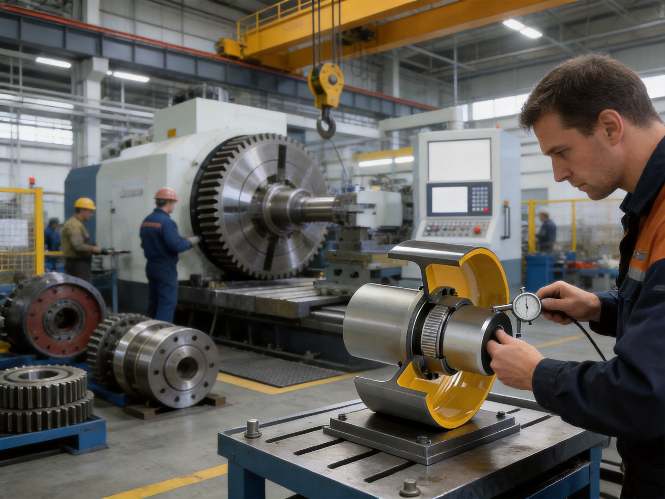
Align the connected shafts according to the specified radial, angular, and axial limits. Use calibrated alignment equipment where required. The coupling’s ability to compensate for misalignment should not be treated as permission to ignore alignment. Good alignment reduces tooth loading, seal movement, vibration, and heat generation.
Install the brake with the correct clearance and ensure that the brake shoes or pads do not drag on the wheel when released. Check that the braking surface is clean and free of grease. Lubricant intended for the gear chamber must never contaminate the friction surface.
Install a suitable guard around the rotating coupling and brake wheel. The guard should prevent accidental contact while allowing necessary inspection and maintenance. It should also be designed so that it does not interfere with brake movement or cooling.
Lubrication
Gear couplings depend on correct grease selection and quantity. The grease must be compatible with the operating speed, temperature, load, sealing system, and manufacturer’s recommendation. Overfilling can increase churning and temperature, while underfilling can cause rapid tooth wear.
Before adding grease, inspect the sealing system and clean the lubrication fittings or ports. Use clean tools and prevent water, dust, metal chips, and other contaminants from entering the gear chamber. Follow the recommended lubrication interval based on operating hours and environmental severity.
In high-speed or high-temperature applications, lubrication intervals may need to be shorter. In dusty or wet environments, seal condition should be checked frequently. Any leakage, discoloration, metallic particles, or unusual odor in the grease should be investigated.
Inspection
Routine inspection should include coupling vibration, temperature, noise, grease leakage, seal condition, bolt security, shaft movement, brake wheel wear, and brake clearance. A sudden change in vibration or temperature may indicate tooth wear, misalignment, insufficient lubrication, loose hardware, bearing failure, or brake drag.
During planned shutdowns, inspect accessible tooth surfaces for pitting, scoring, cracking, excessive polishing, or abnormal contact patterns. Examine the brake wheel for grooves, heat discoloration, cracks, uneven wear, and excessive runout. Replace damaged seals before contaminants enter the gear chamber.
Maintenance personnel should record inspection findings, grease additions, brake adjustments, component replacements, and operating hours. Trend records help identify gradual deterioration before it becomes an unplanned failure.
Seal Replacement
Seal replacement should be performed in a clean area using approved replacement parts. The sealing surface should be inspected for scoring or damage, and the new seal should be installed without twisting or cutting the sealing lip.
The B2 clearance dimension should be considered when designing the surrounding equipment. If the coupling cannot be moved or opened sufficiently, even a routine seal replacement may require extensive disassembly and long downtime.
Safety Considerations
The GBLZ coupling with brake wheel is a rotating machine component and must be installed, guarded, and maintained by qualified personnel. All work should be performed with the equipment isolated, locked out, and verified to be in a zero-energy condition.
The brake wheel must not be used as a lifting point unless specifically designed and approved for that purpose. The coupling should not be subjected to loads outside its intended torque, speed, alignment, temperature, or environmental limits.
Emergency stopping performance depends on the complete braking system, not only the coupling. Brake control, electrical protection, friction material, brake actuator, load inertia, stopping distance, and fail-safe requirements must be evaluated by the system designer.
Any modification to the coupling, such as unauthorized drilling, welding, machining, or alteration of the brake wheel, can compromise balance and structural integrity. Modifications should only be made with written technical approval from the manufacturer.
Why Choose a Specialized Coupling Manufacturer
Purchasing a drum gear coupling from a specialized manufacturer provides more than access to a standard catalog item. It provides engineering support for the complete transmission problem. Zhongye Heavy Industry Technology (Zhenjiang) Co., Ltd. combines product development, manufacturing, sales, customization, technical consultation, and after-sales service.
The company’s product portfolio covers a wide range of coupling technologies. This allows engineers to recommend a GBLZ coupling when a gear-based solution is appropriate, but also to consider a diaphragm, grid, tire, pin, jaw, safety, universal, or rigid coupling when application conditions require a different principle.
Its manufacturing facilities include dedicated heavy and precision workshops, supporting the production of both large industrial couplings and accurately machined transmission components. The company also offers non-standard design and manufacturing, which is important for replacement projects, unusual shaft arrangements, restricted equipment layouts, and special operating environments.
Strong research and development capability, complete specifications, quality management, advanced testing facilities, reliable production arrangements, and customer-oriented technical support help reduce project risk. These strengths are particularly valuable when the coupling forms part of a safety-critical lifting, hoisting, braking, or high-load transmission system.
Customers can obtain support with model selection, shaft dimensions, brake wheel matching, installation space, lubrication, maintenance planning, material selection, and customized design. Early technical communication helps ensure that the final coupling satisfies both mechanical and operational requirements.
Conclusion
The GBLZ drum gear coupling with brake wheel is a high-capacity mechanical transmission solution for industrial equipment that requires torque transmission, misalignment compensation, and controlled braking in one integrated assembly.
Its principal advantages include a robust metal gear structure, broad torque and speed range, compatibility with multiple bore sizes, integrated brake wheel options, serviceable lubrication design, and suitability for demanding industries such as metallurgy, mining, lifting, ports, water treatment, and papermaking.
Compared with a conventional coupling combined with a separately mounted brake, the integrated design can reduce space requirements, simplify machine layout, and provide a direct braking interface. Compared with many elastic couplings, its metallic gear construction is better suited to high torque, high temperature, heavy shock, and severe industrial operating conditions.
The performance of the product ultimately depends on correct selection, alignment, lubrication, braking-system design, guarding, and maintenance. By combining the GBLZ product range with Zhongye Heavy Industry Technology’s engineering, manufacturing, customization, and quality-control capabilities, customers can obtain a transmission solution adapted to the actual requirements of their machinery.
Questions and Answers
What type of coupling is the GBLZ series?
The GBLZ series is a flexible coupling with non-elastic elements. It uses metal gear engagement to transmit torque and accommodate limited angular, radial, and axial shaft displacement. It also includes an integrated brake wheel.
What does the brake wheel do?
The brake wheel provides a rotating friction surface for a compatible industrial brake. It allows the drive system to decelerate or stop through controlled braking. The required brake must be selected according to torque, speed, inertia, stopping time, duty cycle, and safety requirements.
What is the nominal torque range?
The series covers nominal torque ratings from 0.63 kN·m for GBLZ1 to 125 kN·m for GBLZ14.
What is the maximum allowable speed?
Allowable speed varies by model. The smaller GBLZ1 and GBLZ2 models are listed at up to 4,000 r/min, while larger models operate at lower speeds. GBLZ13 and GBLZ14 are listed at approximately 950 r/min.
What brake wheel diameters are available?
Standard brake wheel diameters include 160, 200, 250, 315, 400, 500, 630, 710, and 800 mm.
Can the coupling compensate for poor alignment?
The coupling can compensate for permitted angular, radial, and axial displacement, but it must still be installed with accurate alignment. Operating beyond the specified limits can cause tooth wear, vibration, heat, seal damage, and premature failure.
What materials are used?
The product is manufactured from high-grade steel or alloy steel, with material and heat-treatment requirements selected according to the model and application. Specific material certificates or special treatments should be confirmed during technical ordering.
What is dimension B2?
B2 is the clearance space required to replace the seal. The surrounding machine structure should provide sufficient access so that seal maintenance can be completed without unnecessary disassembly.
Which industries use this coupling?
Typical industries include metallurgy, mining, lifting, port machinery, water treatment, and papermaking. It may also be suitable for other heavy industrial systems after engineering review.
Can customized couplings be produced?
Yes. The manufacturer undertakes non-standard coupling design and manufacture. Customers should provide shaft drawings, torque and speed data, brake requirements, installation dimensions, environmental conditions, and applicable standards for evaluation.
How often should the coupling be lubricated?
Lubrication frequency depends on speed, load, temperature, operating hours, sealing condition, and environmental contamination. The manufacturer’s recommended grease and service interval should be followed. High-speed, dusty, wet, or high-temperature applications may require more frequent inspection and lubrication.
Can the brake wheel be used without a guard?
No. A rotating brake wheel and coupling should be enclosed by a suitable guard that prevents accidental contact while allowing inspection and maintenance. The guard must not interfere with brake movement or cooling.
References
Q/YG 11005X-2018, Technical Standard for Drum Gear Couplings with Brake Wheels.
GBLZ Series Product Technical Data and Main Dimension Tables, manufacturer-supplied technical documentation.
GBLZ Series Brake Wheel Dimension, Mass, and Moment of Inertia Data, manufacturer-supplied technical documentation.
ISO 9001, Quality Management Systems: Requirements.
General engineering principles for flexible coupling selection, gear coupling lubrication, shaft alignment, and industrial braking-system design.
Product: GBLZ Drum gear coupling with brake wheel (Q/YG 11005X-2018)

- Quick Links
- About
- Products
- Our Service
- News & Events
- Contact
- Products Series
- Flexible Couplings with Non-Elastic Elements
- Flexible Couplings with Metal Elastic Elements
- Flexible Couplings with Non-Metallic Elastic Elements
- Safety Coupling
- Rigid Coupling
- Contact Us
- Tel : +86 511 8572 3800 +86 511 8572 3900
- Mobile : +86 15106109009
- Email : sales@couplingzy.com
- Add:No.1 Zhongye Yingbin Avenue, Gaozi Street, Dantu Economic Development Zone, Zhenjiang City, Jiangsu Province, China.


