:+86 15106109009
:sales@couplingzy.com


 English
 русский
 Español
 عربى
 Português
 Deutsch
 Türk
 Indonesia


MCS Plum-Shaped Elastic Coupling: Design, Performance, Manufacturing Quality, and Industrial Applications
Content
- 1 1. Product Definition and Operating Principle
- 2 2. Structural Advantages of the Double-Flange Design
- 3 3. Plum-Shaped Elastic Element and Torque Transmission
- 4 4. Misalignment Compensation
- 5 5. Performance Characteristics
- 6 6. Product Range and Selection Data
- 7 7. Advantages Compared with Alternative Coupling Types
- 8 8. Manufacturing Process and Quality Assurance
- 9 9. Engineering Strengths and Customization Capability
- 10 10. Applications in Heavy Industry
- 11 11. Installation Recommendations
- 12 12. Maintenance and Service Life
- 13 13. How to Select the Correct MCS Model
- 14 14. Commercial and Technical Advantages
- 15 15. Important Design Limitations
- 16 16. Frequently Asked Questions
- 16.1 What is an MCS plum-shaped elastic coupling?
- 16.2 What standard does the product comply with?
- 16.3 What is the torque range?
- 16.4 What is the maximum speed?
- 16.5 Does the coupling require lubrication?
- 16.6 Can it compensate for shaft misalignment?
- 16.7 Can the coupling be used for frequent starting and reversing?
- 16.8 What industries use this coupling?
- 16.9 How is the elastic element maintained?
- 16.10 Can the product be customized?
- 16.11 How should a model be selected?
- 17 17. Conclusion
- 18 References
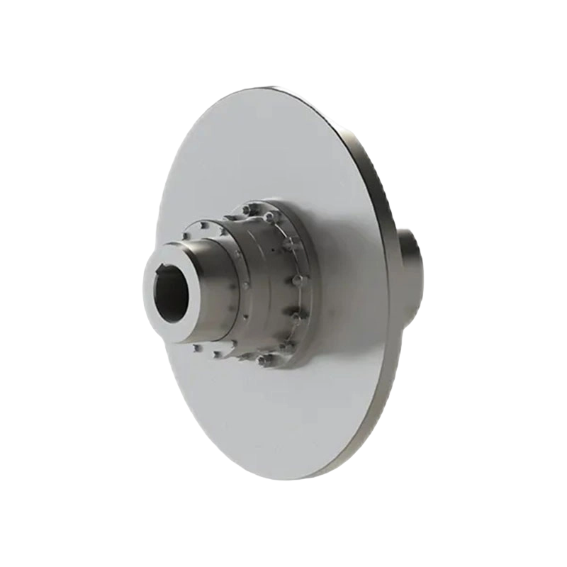
- 19 Product: MCS type plum shaped elastic coupling (Q/YM 35014X-2018)
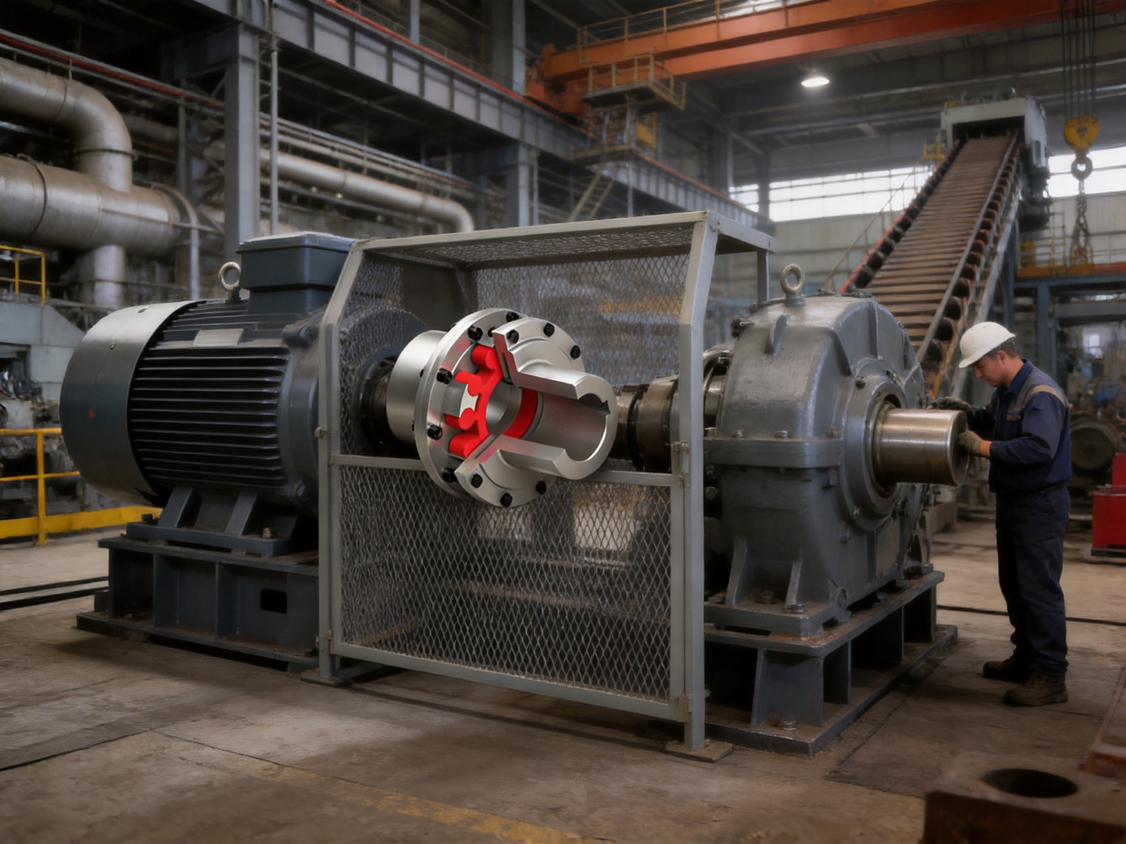
The MCS type plum-shaped elastic coupling is a high-performance flexible shaft coupling designed for reliable power transmission between connected machines. Manufactured in accordance with Q/YM 35014X-2018, this coupling combines a double-flange structure with a non-metallic plum-shaped elastic element. The result is a compact and versatile connection that can transmit torque efficiently while compensating for installation and operating misalignment.
Flexible couplings are essential in industrial power transmission systems because shafts are rarely aligned perfectly under every operating condition. Thermal expansion, foundation settlement, bearing clearance, manufacturing tolerances, shaft deflection, vibration, and changing loads can all create radial, angular, or axial displacement. A rigid connection may transfer these forces directly into bearings, gears, motors, pumps, and driven machinery. The MCS coupling uses an elastic element to reduce this mechanical stress and provide a more forgiving connection.
Its double-flange design is particularly suitable for equipment with matching flanges or dedicated mounting surfaces. Instead of relying exclusively on long shaft extensions or complicated intermediate assemblies, the coupling can be bolted directly to the connected equipment. This arrangement improves installation convenience, supports stable alignment, and helps maintain a compact transmission layout.
The product range covers nominal torques from 28 N·m to 14,000 N·m, allowable speeds up to 8,500 r/min, and shaft hole diameters from 12 mm to 160 mm. This broad range allows one product family to serve light-duty rotating equipment, general industrial machinery, and demanding heavy-duty applications. Typical industries include metallurgy, mining, water conservancy, lifting and conveying, ports, papermaking, and other fields where reliable and low-maintenance torque transmission is required.
1. Product Definition and Operating Principle
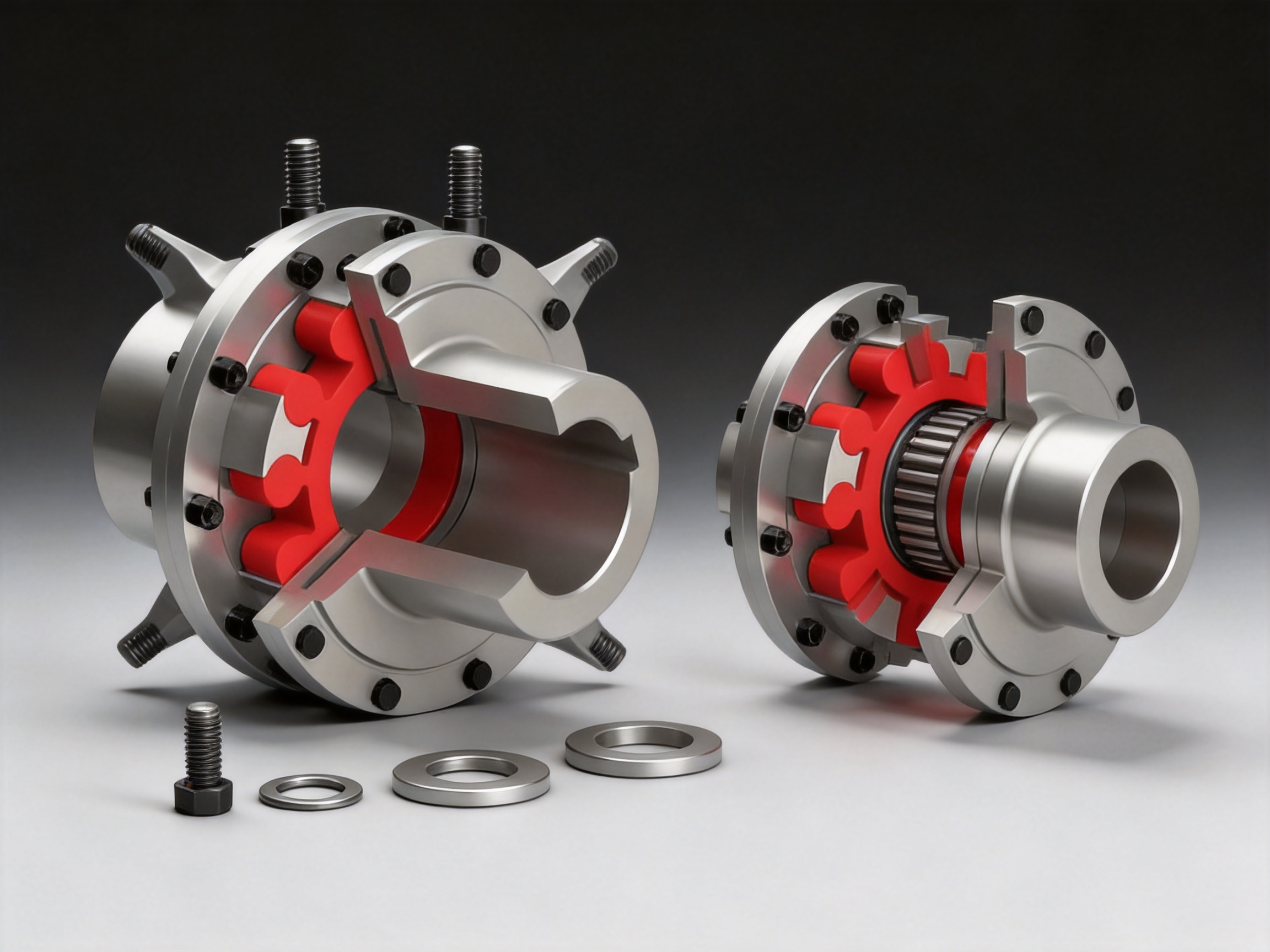
The MCS coupling consists mainly of two flange half couplings, projecting claws, flange connectors, a plum-shaped elastic element, and matching bolts, nuts, and washers. The two half couplings are installed on the driving and driven sides of the transmission system. Their claws are arranged around the circumference and engage with the lobes of the elastic element.
When the driving shaft rotates, torque passes from the first flange half coupling to the elastic element and then to the second flange half coupling. The elastic element is compressed locally between the opposing claws. This compression transfers torque while allowing controlled deformation. Because the flexible element is not a rigid metallic gear or solid pin, it can absorb a degree of relative movement between the shafts.
The double-flange configuration provides a bolted connection at both ends. It can be directly combined with the flange of a motor, gearbox, pump, fan, conveyor, rolling mill, or other machine. The physical flange interface helps define the relative position of the connected equipment and may simplify assembly where shaft access is limited.
The plum-shaped element is the functional center of the coupling. Its lobes are positioned between the claws of the two half couplings. During operation, the elastic material deforms as torque changes and as the shafts experience limited displacement. This deformation reduces the direct transmission of shock and vibration while maintaining effective torque transfer.
The coupling is non-metallic elastic in its torque-transmitting element. This gives it several practical benefits. It does not require lubrication, it can provide electrical insulation between the two shaft systems, and it reduces the number of wear-prone metallic contact surfaces. The simplified construction also supports easier inspection and replacement compared with many lubricated gear or grid couplings.
2. Structural Advantages of the Double-Flange Design
A major advantage of the MCS type is the use of a double-flange structure. Many shaft couplings depend on hubs mounted to shaft ends and connected by an elastomeric insert. The MCS design adds a flange interface on both sides, making it suitable for equipment that has a flange connection or a short shaft arrangement.
The flange-to-flange installation method can reduce assembly complexity. Technicians can position the coupling between the two machines, align the bolt holes, and secure the connection with the specified fasteners. When the connected equipment has been designed for a flange-mounted coupling, this approach can reduce the need for additional brackets, long spacer shafts, or separate adapter components.
The flange structure also contributes to installation stability. A properly machined flange provides a defined mounting surface and a repeatable connection. When the flange faces, bolt circles, and center references are manufactured accurately, the coupling can help maintain the intended coaxial relationship between the connected equipment.
Another benefit is improved packaging flexibility. In confined machine rooms, pump stations, steel plants, and lifting equipment, the available distance between drive components may be limited. A compact double-flange coupling can provide a practical solution where a longer conventional shaft coupling would be difficult to install or remove.
Flange connections may also simplify maintenance planning. Instead of dismantling a large portion of the machine, maintenance personnel can often access the fasteners and inspect the elastic element from the coupling area. The actual maintenance method depends on the equipment arrangement and safety procedures, but the structural concept supports efficient service access.
3. Plum-Shaped Elastic Element and Torque Transmission
The plum-shaped elastic element is named for its radial lobe arrangement, which resembles a plum blossom or quincunx pattern. Its geometry is designed to fit between the claws of the two half couplings. This creates multiple load-transmission points around the circumference rather than concentrating the entire load in one location.
When torque is applied, the lobes are pressed against the coupling claws. The elastic element distributes the load across several contact areas, helping the coupling transmit torque smoothly. The exact load distribution depends on the selected model, element material, operating torque, rotational speed, alignment condition, and manufacturing tolerances.
Elastic deformation also helps moderate transient loads. Motors, conveyors, pumps, fans, hoists, and other industrial machines may experience starting torque, reversing torque, load fluctuations, or brief impacts. The elastic element can absorb part of these disturbances and reduce the severity of the torque peak transmitted to the connected machinery.
Compared with a rigid coupling, the MCS design offers substantially greater tolerance to normal installation errors and operating displacement. Compared with some highly flexible couplings, the plum-shaped arrangement remains compact and mechanically straightforward. It provides a balance between flexibility, torque capacity, maintenance simplicity, and dimensional efficiency.
The elastic element is a replaceable working component. In normal service, its condition should be checked for cracking, hardening, tearing, excessive wear, deformation, or chemical damage. Replacement intervals depend on load, speed, temperature, environmental conditions, alignment, and operating cycles. Using the correct replacement element is important because material hardness and geometry directly influence coupling performance.
4. Misalignment Compensation
One of the most important reasons to select a flexible coupling is the need to accommodate shaft displacement. The MCS coupling is designed to compensate for three principal types of misalignment: radial displacement, angular displacement, and axial displacement.
4.1 Radial Displacement
Radial displacement occurs when the centerlines of two shafts are parallel but offset from each other. It may result from installation tolerances, foundation movement, bearing wear, thermal expansion, or deflection under load. The elastic element deforms between the claws to accommodate a limited amount of this offset.
Radial compensation does not eliminate the need for proper alignment. Excessive parallel misalignment can increase elastic deformation, generate heat, accelerate wear, and impose additional loads on connected bearings. The coupling should therefore be installed within the allowable values specified for the selected model and application.
4.2 Angular Displacement
Angular displacement occurs when the two shaft centerlines intersect at an angle rather than remaining parallel. The flexible element can tilt and deform within the claw arrangement, allowing the coupling to continue transmitting torque while reducing the bending load transferred between shafts.
Angular misalignment can be caused by uneven mounting surfaces, incorrect machine positioning, shaft deflection, or movement during operation. Proper flange face inspection and precision alignment remain essential because a flexible coupling is intended to compensate for limited movement, not correct severe installation errors.
4.3 Axial Displacement
Axial displacement is movement along the shaft axis. It may be caused by thermal growth, bearing movement, hydraulic thrust, or assembly tolerances. The elastic element permits a degree of axial movement while maintaining the connection between the two half couplings.
The permitted axial displacement must be considered during equipment design. The coupling should not be used as a substitute for a dedicated thrust-control system, and the connected machines must be capable of supporting their own axial loads. Correct end float, shaft shoulder position, and flange spacing are important during installation.
5. Performance Characteristics
The MCS range offers a combination of high transmission efficiency, vibration reduction, electrical insulation, and low maintenance. Under appropriate selection and operating conditions, transmission efficiency can exceed 99 percent. This supports efficient use of motor power and helps reduce unnecessary energy losses in rotating equipment.
Its elastic buffering behavior is valuable in systems exposed to starting and stopping cycles. When the motor begins rotating, the elastic element can moderate the initial torque transfer. During a sudden load change, it can reduce the intensity of the shock passed into the shafts and bearings. This buffering effect may contribute to longer service life for the wider transmission system.
The coupling can also reduce mechanical noise. Rigid metallic contact between transmission components may generate impact noise when alignment changes or torque fluctuates. The non-metallic element acts as a damping medium, reducing some of the vibration energy that would otherwise be transmitted directly through the shaft line.
Electrical insulation is another useful characteristic. Because the torque-transmitting element is non-metallic, the coupling can interrupt certain stray-current paths between the connected machines. This can help reduce the risk of electrical current passing through bearings or other sensitive components. The coupling should not, however, be treated as the only grounding or electrical protection measure in a system.
The product is designed for working temperatures from approximately -35 °C to +80 °C. Temperature suitability depends on the elastic element material, operating duration, speed, load, and environmental exposure. In applications involving higher temperatures, aggressive chemicals, oil contamination, or outdoor weathering, the element material and protection requirements should be confirmed before ordering.
6. Product Range and Selection Data
The MCS product family contains fourteen principal sizes. Nominal torque ratings range from 28 N·m for MCS1 to 14,000 N·m for MCS14. Maximum torque ratings range from 50 N·m to 25,200 N·m. Allowable speed decreases as coupling size and torque capacity increase, reflecting the relationship between rotating mass, diameter, balance, and mechanical stress.
| Type | Nominal Torque Tn (N·m) | Maximum Torque Tmax (N·m) | Allowable Speed (r/min) | Typical Shaft Hole Range (mm) | L (mm) | L0 (mm) | D (mm) | D1 (mm) | Element Type |
|---|---|---|---|---|---|---|---|---|---|
| MCS1 | 28 | 50 | 8500 | 12–25 | 35 | 98 | 50 | 90 | MT1 |
| MCS2 | 50 | 100 | 7600 | 16–30 | 38 | 108 | 60 | 100 | MT2 |
| MCS3 | 112 | 200 | 6900 | 20–32 | 40 | 117 | 70 | 110 | MT3 |
| MCS4 | 160 | 288 | 6200 | 22–40 | 45 | 130 | 85 | 125 | MT4 |
| MCS5 | 355 | 640 | 5000 | 25–45 | 50 | 150 | 105 | 150 | MT5 |
| MCS6 | 450 | 810 | 4100 | 30–48 | 55 | 167 | 125 | 185 | MT6 |
| MCS7 | 710 | 1280 | 3700 | 35–55 | 60 | 185 | 145 | 205 | MT7 |
| MCS8 | 1250 | 2250 | 3100 | 45–65 | 70 | 209 | 168 | 240 | MT8 |
| MCS9 | 2000 | 3600 | 2800 | 55–80 | 80 | 240 | 198 | 270 | MT9 |
| MCS10 | 3150 | 5670 | 2500 | 60–100 | 90 | 268 | 228 | 305 | MT10 |
| MCS11 | 5000 | 9000 | 2200 | 70–120 | 100 | 308 | 258 | 350 | MT11 |
| MCS12 | 7100 | 12780 | 1900 | 80–130 | 115 | 345 | 298 | 400 | MT12 |
| MCS13 | 12500 | 22500 | 1600 | 90–150 | 125 | 373 | 358 | 460 | MT13 |
| MCS14 | 14000 | 25200 | 1500 | 100–160 | 135 | 383 | 400 | 500 | MT14 |
The shaft hole values in the product data represent available bore options rather than a single universal bore. Some sizes include starred bore options that may be subject to specific machining or configuration conditions. Final bore selection should be confirmed according to shaft diameter, keyway requirements, fit class, locking method, and the dimensional drawing for the selected coupling.
For a complete engineering selection, users should consider nominal torque, peak torque, motor starting characteristics, service factor, speed, shaft diameter, bore length, available installation space, environmental temperature, misalignment, and the frequency of starting or reversing. Selecting a coupling only by matching the average operating torque may result in inadequate capacity during starting or shock loading.
7. Advantages Compared with Alternative Coupling Types
7.1 Compared with Rigid Couplings
Rigid couplings are suitable when shafts are accurately aligned and no relative movement is expected. They are often simple and economical, but they transmit shaft displacement directly into the connected equipment. Any error in alignment can increase bearing loads and vibration.
The MCS coupling provides a more tolerant connection. Its elastic element compensates for limited displacement and absorbs vibration. This makes it more suitable for equipment where alignment may change during operation or where the drive system experiences frequent load variations.
7.2 Compared with Lubricated Gear Couplings
Gear couplings can provide high torque capacity and substantial flexibility, but they normally require periodic lubrication and inspection of gear teeth, seals, and lubricant condition. Maintenance can be more demanding, especially in dusty, wet, or difficult-to-access industrial environments.
The MCS coupling operates without lubrication. Its maintenance focus is primarily on fastener condition, alignment, flange integrity, and the state of the elastic element. This can reduce routine servicing requirements and prevent lubricant leakage or contamination near the machine.
7.3 Compared with Grid Couplings
Grid couplings provide useful shock absorption through a metallic grid and lubricated tooth grooves. However, they may require a split cover, grease, and careful inspection of the grid and hubs. The MCS coupling has a simpler non-metallic elastic element and does not depend on a lubricated grid for torque transfer.
For installations where clean operation, insulation, and quick service are priorities, the MCS construction can offer practical advantages. The final choice still depends on torque, speed, environmental conditions, and the level of flexibility required.
7.4 Compared with Diaphragm Couplings
Diaphragm couplings are capable of high-speed operation and precise motion transmission, particularly in applications requiring low backlash. They may be preferred for turbines, compressors, or precision systems. However, they can be more sensitive to installation conditions and may require greater manufacturing precision.
The MCS coupling is often more attractive for general industrial machinery, where vibration damping, overload tolerance, low maintenance, and cost-effective replacement are important. Its elastic element provides damping that a thin metallic diaphragm does not provide in the same way.
7.5 Compared with Jaw Couplings
Jaw couplings also use an elastomeric element and are widely used for compact machinery. The MCS type distinguishes itself through its double-flange arrangement, broader heavy-duty range, and suitability for direct flange-mounted equipment. It can be used where a conventional hub-and-bore jaw coupling does not provide the required flange interface or torque capacity.
8. Manufacturing Process and Quality Assurance
The performance of a flexible coupling depends not only on its design but also on the quality of its manufacturing. Dimensional accuracy, material consistency, balance, surface finish, bolt-hole position, and elastic element quality all affect operating reliability. A well-designed coupling can perform poorly if the flange faces are distorted or the claws are manufactured outside their required tolerances.
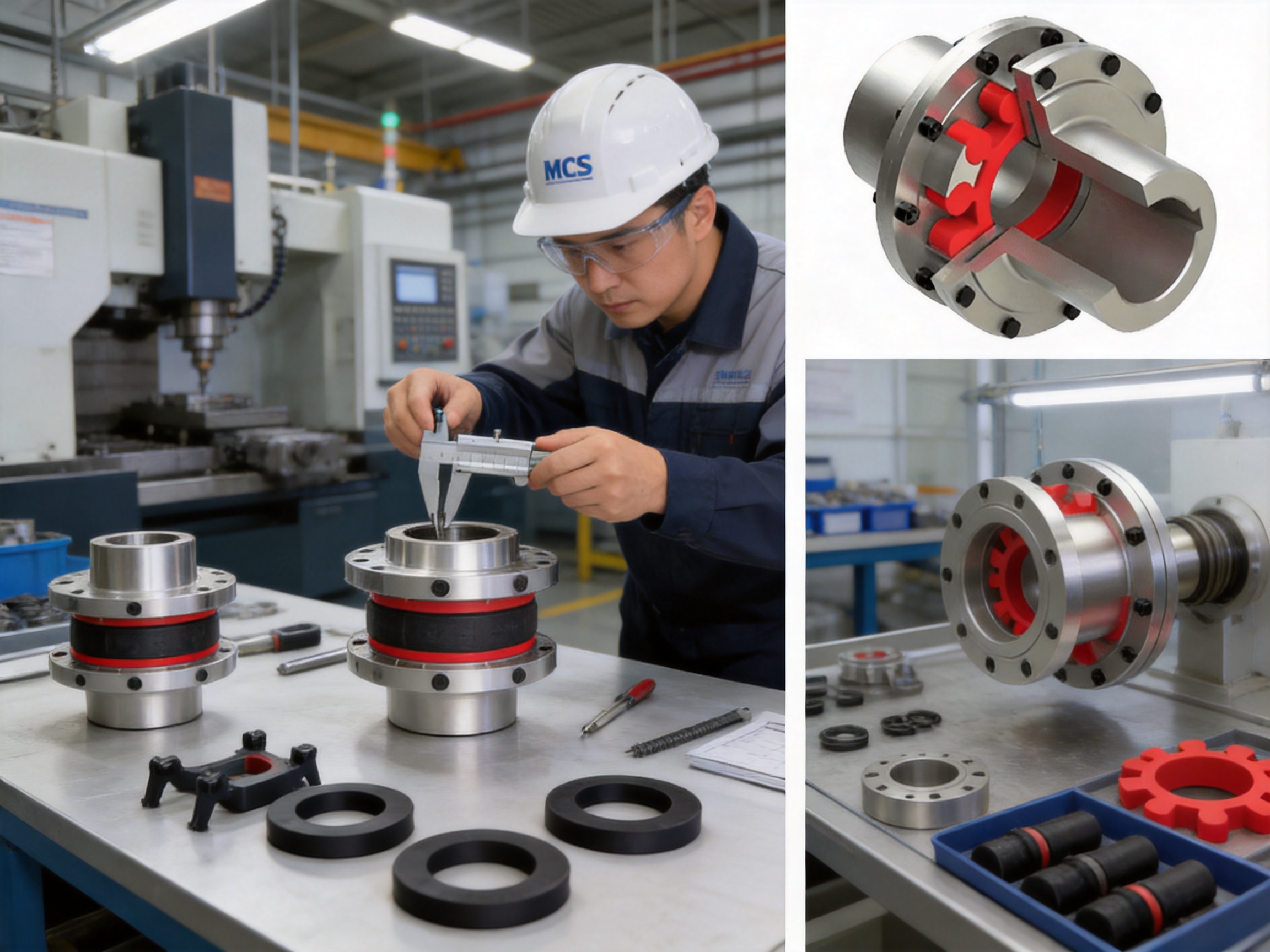
The manufacturer operates an integrated research, development, manufacturing, and sales system. Its production facilities include a heavy workshop, a precision workshop, office and technical facilities, warehouse space, and supporting logistics areas. This type of integrated layout can help coordinate design review, production scheduling, quality inspection, inventory management, and customer service.
The manufacturing process begins with engineering confirmation. Customer data such as torque, speed, shaft dimensions, flange dimensions, environmental conditions, and equipment type are reviewed before production. For standard MCS models, the relevant product specifications and Q/YM 35014X-2018 requirements guide the design and inspection process. For non-standard applications, engineering personnel can develop modified dimensions or special coupling arrangements.
Material preparation is the next important stage. The metallic half couplings and flange components must have sufficient strength, dimensional stability, and machinability. Incoming material inspection may include verification of material certificates, dimensions, surface condition, and other requirements defined by the production and quality system.
Machining operations shape the flange faces, outer diameters, claw profiles, shaft bores, keyways, bolt holes, and locating features. Precision machining is particularly important for the interface surfaces. The flange face must provide stable contact, while the bolt-circle and locating dimensions must match the connected equipment. Bore and keyway accuracy influences torque transfer and shaft fit.
Process control should be applied throughout machining rather than only at final inspection. In-process checks can identify dimensional deviation before a component proceeds to later operations. This helps reduce rework and ensures that critical features remain within the required tolerances.
After machining, components may undergo deburring, cleaning, surface treatment, marking, and final dimensional inspection. Sharp edges and machining residue must be removed to protect personnel, improve assembly, and prevent damage to the elastic element. Surface protection is selected according to the material and intended operating environment.
The plum-shaped elastic element requires separate attention. Its geometry, resilience, hardness, and surface condition influence the coupling’s torque capacity and damping behavior. The element should be formed or molded consistently so that its lobes engage correctly with the claws. Inspection may include dimensional checks, visual examination, material verification, and functional assessment according to internal quality procedures.
Assembly inspection confirms that the half couplings, elastic element, bolts, nuts, washers, and other components match the specified model. Fasteners must be correct in size and grade, and bolt-hole alignment must allow proper installation without forced assembly. Where required, balancing and rotational checks can be performed to support high-speed operation.
Testing facilities and strict quality-control procedures provide an additional safeguard. Depending on the order and product configuration, inspection may cover torque-related dimensions, shaft bores, flange runout, perpendicularity, concentricity, surface condition, component completeness, and packaging protection. Quality documentation supports traceability from production through shipment.
The company maintains an ISO 9001 quality-management approach and emphasizes reliable production guarantees, advanced testing facilities, complete specifications, and technical support. These capabilities are valuable for customers purchasing couplings for continuous-process industries, where a component failure may cause production interruption and significant secondary costs.
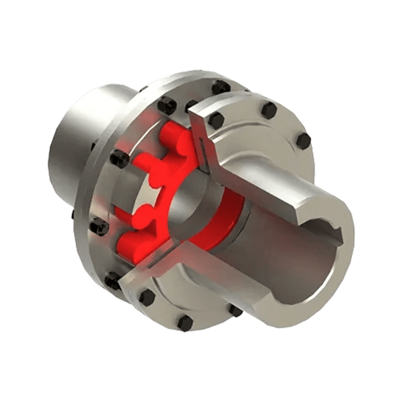
MCS type plum shaped elastic coupling (Q/YM 35014X-2018)
9. Engineering Strengths and Customization Capability
Standardized products provide efficient selection and stable production, but many industrial installations require special dimensions. Shaft diameters, flange bolt circles, center distances, keyways, mounting constraints, and environmental conditions may vary between machines. The manufacturer supports customized and non-standard coupling design in addition to the standard MCS range.
Customization may include special bore dimensions, alternative keyways, modified flange dimensions, different connection interfaces, customized overall length, special materials, protective coatings, or adaptations for unusual installation spaces. Any modification must be evaluated for strength, balance, misalignment capability, and compatibility with the selected elastic element.
Engineering consultation is especially important for systems with high inertia, frequent reversing, repeated starting, braking, or severe impact loads. In such cases, the average operating torque may not represent the real coupling demand. Engineers should assess acceleration torque, peak torque, duty cycle, torsional vibration, and the possibility of resonance.
The manufacturer’s product portfolio includes many types of couplings, including toothed, pin, universal, tire, jaw, star, diaphragm, drum, grid, Oldham, flange, roller-chain, safety, and other customized couplings. This broad product knowledge allows engineers to compare different coupling principles rather than recommending a single solution for every application.
For customers with equipment portfolios, this can simplify procurement and technical communication. A single coupling specialist may be able to support standard flexible couplings, high-torque industrial couplings, safety couplings, and custom transmission components across multiple plants and machine types.
10. Applications in Heavy Industry
10.1 Metallurgical Equipment
Steel and non-ferrous metal production equipment frequently operates under high loads, repeated starts, shock conditions, elevated temperatures, and difficult maintenance access. Conveyors, cooling systems, rolling equipment, pumps, fans, and auxiliary drives all require reliable power transmission.
The MCS coupling can be used where a flexible connection is needed to reduce vibration and compensate for limited shaft displacement. Its no-lubrication design is useful in areas where grease contamination or frequent manual servicing would be undesirable. For high-load applications, the coupling must be selected using the correct service factor and maximum torque conditions.
10.2 Mining Machinery
Mining systems often work in dusty environments and may experience variable loads. Crushers, feeders, pumps, conveyors, screening machines, and ventilation systems can impose shock loads and repeated torque fluctuations.
The elastic element can help absorb some of these fluctuations and reduce the transmission of impact to the drive system. Protective covers and environmental safeguards should be considered where abrasive dust, water, mud, or chemicals may contact the coupling.
10.3 Water Conservancy and Pumping Systems
Pumps and water-control equipment often operate for long periods and may be installed in locations where maintenance access is restricted. Reliable alignment and low-maintenance operation are important for water-treatment plants, irrigation systems, drainage stations, pumping stations, and hydraulic infrastructure.
The MCS flange structure can simplify integration with motor-pump assemblies that use flanged interfaces. Its vibration-damping characteristics may also help reduce noise and mechanical stress in continuously operating pumping equipment.
10.4 Lifting and Conveying Equipment
Cranes, hoists, winches, elevators, conveyors, and material-handling systems are exposed to frequent starts, stops, reversals, and load changes. These operating cycles create torque transients that should be considered when selecting a coupling.
The elastic component can moderate the transfer of sudden torque changes. For lifting applications, the coupling should be selected with attention to braking torque, emergency stops, duty classification, safety requirements, and the consequences of coupling failure. A flexible coupling is one component of the transmission system and should not replace required brakes, overload protection, or mechanical safety devices.
10.5 Papermaking Machinery
Papermaking lines often contain numerous shafts, pumps, fans, rolls, dryers, and auxiliary drives. Some parts of the process demand continuous operation and stable speed. Excessive vibration or misalignment may affect both equipment reliability and product quality.
The MCS coupling can provide a compact connection with vibration damping and electrical insulation. Its range of sizes allows use in both smaller auxiliary systems and larger industrial drives, subject to the required speed and torque calculations.
10.6 Port and Material-Handling Equipment
Port machinery operates outdoors and may encounter humidity, salt-laden air, dust, variable loading, and frequent movement. Ship loaders, conveyors, cranes, winches, and bulk-handling systems need robust transmission components and practical maintenance arrangements.
When the coupling is properly protected and specified for the environment, its simple, lubrication-free structure can help reduce routine service requirements. Surface treatment, sealing, inspection frequency, and replacement-element material should be selected according to the actual site conditions.
11. Installation Recommendations
Before installation, verify the coupling model, shaft hole diameter, keyway, flange dimensions, elastic element type, fastener specification, and overall length. Compare these details with the equipment drawing and purchase documentation. Do not attempt to force a coupling onto a shaft with an incorrect bore or keyway.
Inspect the shafts and flanges for burrs, corrosion, dirt, impact marks, and damage. Shaft surfaces should be clean and free from material that could prevent the half coupling from seating correctly. Flange faces should be checked for flatness, cleanliness, and proper contact.
Measure the shaft alignment before final tightening. Radial and angular alignment should be brought within the allowable values for the selected coupling. Although the elastic element compensates for limited misalignment, precise initial alignment reduces its working strain and extends service life.
Install keys, hubs, flanges, bolts, nuts, and washers according to the approved drawing and assembly instructions. Fasteners should be tightened in a controlled sequence and to the specified torque. Uneven tightening can distort the flange or introduce runout.
Check that the elastic element is correctly positioned between the claws. It should not be twisted, pinched, cut, or forced into an incorrect orientation. There should be no interference between the rotating parts and stationary guards, bases, piping, cables, or other equipment.
After installation, rotate the shaft by hand where possible to check for binding. During the first trial run, observe vibration, noise, temperature, fastener security, and general operating behavior. The equipment should be stopped immediately if there is abnormal impact, severe vibration, burning odor, visible deformation, or unusual movement.
12. Maintenance and Service Life
The MCS coupling is designed for no lubrication, but no-maintenance does not mean no inspection. A regular inspection program should include the elastic element, flange bolts, shaft fits, keyways, guards, and alignment condition.
The elastic element should be inspected for cracks, cuts, hardening, swelling, discoloration, surface deterioration, or excessive permanent deformation. Chemical exposure, excessive temperature, overloading, misalignment, and high-frequency reversing can accelerate element degradation.
Fasteners should be checked for looseness, corrosion, damaged threads, and signs of fretting. A loose bolt can produce local movement, enlarge a bolt hole, damage the flange, and create secondary vibration. Replacement fasteners should meet the required specification and should not be substituted with unsuitable hardware.
Changes in vibration or noise can indicate a developing problem. Increased vibration may result from coupling misalignment, elastic element deterioration, shaft damage, bearing problems, unbalanced rotating parts, or a loose mounting foundation. Troubleshooting should consider the complete drive system rather than focusing on the coupling alone.
Replacement of the elastic element should be performed with the machine isolated and locked out. The coupling must be supported safely, and stored energy in the drive system must be released. After replacement, alignment and fastener tightening should be checked again before the machine is returned to service.
Service life cannot be represented by one fixed number because operating conditions vary widely. Continuous operation at moderate torque may produce a different service life from frequent reversing at high peak torque. Correct selection, alignment, environmental protection, and inspection are the main factors controlling long-term performance.
13. How to Select the Correct MCS Model
Begin by determining the required nominal torque. Motor power and speed can be used to calculate the approximate operating torque, but the result should then be multiplied by an appropriate service factor. The service factor should account for load type, starting frequency, duty cycle, impact, reversing, braking, and the driven machine’s characteristics.
Next, evaluate maximum torque. The coupling’s maximum torque rating should exceed the highest foreseeable transient torque, not merely the normal running torque. If the system includes a high-inertia load, direct-on-line starting, frequent reversing, or emergency braking, peak torque may be substantially higher than the calculated steady-state value.
Confirm the operating speed. The selected model must have an allowable speed greater than the actual operating speed, including any overspeed condition that may occur during testing or control-system failure. Higher speed also increases the importance of balance, concentricity, flange runout, and secure assembly.
Check both shaft diameters and the available bore options. The coupling must fit the shafts without excessive clearance or unauthorized modification. Consider the required keyway, shaft extension, hub length, and any axial movement needed during assembly.
Verify the flange interface. Bolt-circle diameter, number of holes, hole diameter, pilot diameter, flange thickness, and overall length must match the connected equipment. If the standard dimensions do not match, a customized design may be more suitable than making uncontrolled field modifications.
Finally, review the environment. Temperature, water, dust, oil, solvents, ultraviolet exposure, corrosive gases, and installation altitude may influence material selection and protection requirements. The correct elastic element must be used for the actual operating conditions.
14. Commercial and Technical Advantages
The MCS coupling offers several advantages for original equipment manufacturers, maintenance departments, and industrial distributors. Its broad torque range reduces the need to source completely different coupling designs for every machine. Standardized model sizes also simplify replacement planning and spare-parts management.
The double-flange construction supports direct integration with suitable equipment. This can reduce the number of separate adapter parts and make the coupling easier to include in a new machine design. For replacement projects, the flange dimensions and shaft interfaces can be reviewed against existing equipment to determine whether a standard or customized model is appropriate.
The non-metallic elastic element provides damping and electrical insulation without requiring lubrication. This combination can be especially valuable in environments where maintenance access is limited or where grease is undesirable. The element is also a replaceable wear component, allowing the main metallic coupling bodies to remain in service when they are still within acceptable condition.
The manufacturer’s ability to design and produce various coupling types is another advantage. Customers can receive technical comparison and application guidance rather than selecting solely from a catalog. This is useful when a project includes several transmission systems with different load, speed, flexibility, and safety requirements.
Customization support further improves application flexibility. Non-standard bore sizes, flange interfaces, dimensions, materials, and special operating conditions can be assessed by the engineering team. A customized coupling should always be supported by approved drawings and technical calculations so that modifications do not compromise torque capacity or balance.
15. Important Design Limitations
Every coupling type has operating limits. The MCS coupling should not be used beyond its rated torque, speed, temperature, or misalignment capacity. Severe misalignment can shorten the service life of the elastic element and impose unacceptable loads on the connected shafts and bearings.
The coupling is not intended to compensate for poor foundation construction, loose bearings, bent shafts, severely distorted flanges, or incorrect machine installation. These underlying problems must be corrected rather than relying on the elastic element to absorb them.
Environmental compatibility must also be confirmed. Certain oils, solvents, chemicals, and elevated temperatures may damage a non-metallic element. If the coupling is installed outdoors or in a corrosive atmosphere, suitable guards and surface protection should be used.
For very high-speed precision machinery, torsional vibration analysis and dynamic balancing may be required. The coupling’s mass moment of inertia, shown in the product data, should be included in system calculations. The selected model must be evaluated as part of the complete rotating assembly.
16. Frequently Asked Questions
What is an MCS plum-shaped elastic coupling?
It is a flexible shaft coupling that uses two flange half couplings and a plum-shaped non-metallic elastic element to transmit torque. The element sits between projecting claws and provides controlled flexibility, vibration damping, and limited misalignment compensation.
What standard does the product comply with?
The product is manufactured in accordance with Q/YM 35014X-2018 as specified in the supplied product information. The final product configuration should be confirmed against the applicable technical drawing and order documentation.
What is the torque range?
The MCS series covers nominal torque ratings from 28 N·m to 14,000 N·m. Maximum torque ratings range from 50 N·m to 25,200 N·m, depending on the model.
What is the maximum speed?
The highest listed allowable speed is 8,500 r/min for MCS1. Allowable speed decreases for larger models, reaching 1,500 r/min for MCS14. The selected model must be checked against the actual operating speed and balance requirements.
Does the coupling require lubrication?
No. The MCS coupling is designed as a no-lubrication flexible coupling. Routine inspection is still required for the elastic element, fasteners, alignment, flange condition, and protective guards.
Can it compensate for shaft misalignment?
Yes. It can compensate for limited radial, angular, and axial displacement through deformation of the elastic element. The coupling should still be installed with accurate alignment because excessive displacement will shorten element life.
Can the coupling be used for frequent starting and reversing?
It is suitable for applications involving frequent starting and forward or reverse rotation when the selected model is correctly rated for the resulting peak torque and duty cycle. The starting, braking, and reversing conditions should be included in the engineering selection.
What industries use this coupling?
Typical applications include metallurgy, mining, water conservancy, pumping, lifting, conveying, papermaking, ports, and other industrial machinery sectors. It can also be considered for custom equipment where a flanged flexible connection is required.
How is the elastic element maintained?
Inspect it for cracks, cuts, hardening, swelling, discoloration, deformation, and unusual wear. Replace it if damage or excessive deterioration is found. The machine must be isolated and made safe before inspection or replacement.
Can the product be customized?
Yes. Customization may include shaft bores, keyways, flange dimensions, center distances, materials, protective treatments, and other non-standard requirements. Customized designs should be confirmed through engineering drawings and technical evaluation.
How should a model be selected?
Consider operating torque, peak torque, service factor, speed, shaft diameters, bore and keyway requirements, flange dimensions, misalignment, temperature, environment, starting frequency, and installation space. Selecting only by average motor torque is not sufficient for demanding applications.
17. Conclusion
The MCS type plum-shaped elastic coupling is a practical solution for industrial shaft connection where reliable torque transmission, vibration reduction, compact installation, and low maintenance are important. Its double-flange structure supports direct equipment connection, while the non-metallic elastic element compensates for limited radial, angular, and axial displacement.
The product range covers fourteen sizes, nominal torques from 28 N·m to 14,000 N·m, speeds up to 8,500 r/min, and shaft holes up to 160 mm. This broad selection makes the series suitable for both general industrial equipment and demanding heavy-duty machinery.
Compared with rigid couplings, the MCS design provides greater flexibility and shock absorption. Compared with lubricated gear or grid couplings, it offers simpler maintenance and no lubrication requirement. Compared with compact elastomeric alternatives, its double-flange construction provides a distinct advantage for flange-mounted equipment and heavy industrial applications.
Product reliability is supported by integrated research and development, manufacturing, precision machining, testing, quality control, customization, and technical service capabilities. The company’s experience across multiple coupling technologies allows it to provide application-specific recommendations and non-standard design solutions when standard dimensions are insufficient.
For the best results, users should select the coupling according to complete operating conditions, install it with accurate alignment, protect it from unsuitable environments, and inspect the elastic element and fasteners regularly. When correctly specified and maintained, the MCS plum-shaped elastic coupling can contribute to stable, efficient, and durable operation across a wide range of industrial transmission systems.
References
Q/YM 35014X-2018, Technical Requirements for MCS Type Plum-Shaped Elastic Couplings.
ISO 9001, Quality Management Systems—Requirements.
Industrial Power Transmission Coupling Selection and Maintenance Principles.
Engineering Practice for Shaft Alignment, Flexible Couplings, and Rotating Machinery.
Manufacturer-supplied MCS Type Coupling Product Data and Dimensional Schedule.
Product: MCS type plum shaped elastic coupling (Q/YM 35014X-2018)

- Quick Links
- About
- Products
- Our Service
- News & Events
- Contact
- Products Series
- Flexible Couplings with Non-Elastic Elements
- Flexible Couplings with Metal Elastic Elements
- Flexible Couplings with Non-Metallic Elastic Elements
- Safety Coupling
- Rigid Coupling
- Contact Us
- Tel : +86 511 8572 3800 +86 511 8572 3900
- Mobile : +86 15106109009
- Email : sales@couplingzy.com
- Add:No.1 Zhongye Yingbin Avenue, Gaozi Street, Dantu Economic Development Zone, Zhenjiang City, Jiangsu Province, China.


