:+86 15106109009
:sales@couplingzy.com


 English
 русский
 Español
 عربى
 Português
 Deutsch
 Türk
 Indonesia


HCL Elastic Pin Coupling with Brake Wheel: Integrated Power Transmission and Reliable Braking
Content
- 1 1. Product Overview
- 2 2. Working Principle of the HCL Coupling
- 3 3. Main Technical Characteristics
- 4 4. Selected Technical Parameters
- 5 5. Advantages Compared with Conventional Coupling Arrangements
- 6 6. Manufacturing Process and Quality Approach
- 7 7. Manufacturing Strengths and Supplier Capability
- 8 8. Application Areas
- 9 9. Coupling Selection Guidelines
- 10 10. Installation and Maintenance Recommendations
- 11 11. Customization and Non-Standard Solutions
- 12 12. Why Choose This Coupling for Heavy-Duty Transmission
- 13 13. Frequently Asked Questions
- 13.1 What is an HCL elastic pin coupling with brake wheel?
- 13.2 What is the main advantage of integrating the brake wheel?
- 13.3 What torque range does the HCL series cover?
- 13.4 What is the highest permissible speed in the series?
- 13.5 Can the coupling compensate for shaft misalignment?
- 13.6 Where is this coupling commonly used?
- 13.7 Do the elastic pins require regular inspection?
- 13.8 Can the HCL coupling be customized?
- 13.9 How should the brake wheel be maintained?
- 13.10 Are the listed mass and inertia values universal for every configuration?
- 13.11 What information is needed for product selection?
- 14 14. Conclusion
- 15 References
- 16 Product: HCL type elastic pin coupling with brake wheel (Q/YZ31002X-2018)
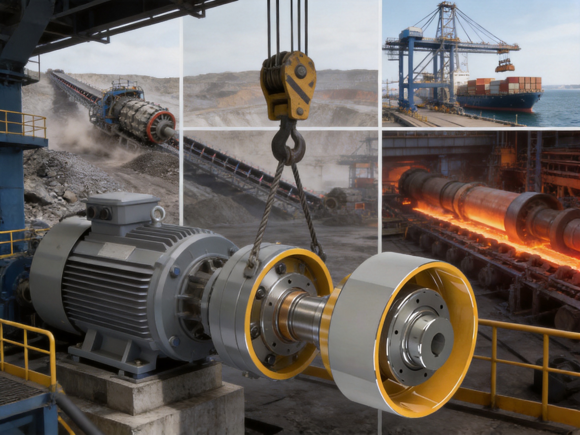
Modern industrial machinery increasingly requires transmission components that can perform more than one mechanical function. A coupling must transfer torque efficiently, accommodate unavoidable shaft misalignment, withstand shock and vibration, and operate reliably under changing loads. In lifting equipment, metallurgical machinery, mining systems, and port installations, the coupling may also need to work together with a braking system while occupying limited installation space. The HCL type elastic pin coupling with brake wheel is designed for this demanding operating environment.
Manufactured according to the Q/YZ31002X-2018 technical standard, the HCL coupling combines a flexible non-metallic elastic element with an integrated brake wheel. This configuration allows the component to transmit rotational power and provide a dedicated braking surface within one compact assembly. The result is a practical solution for equipment designers seeking efficient space utilization, dependable torque transmission, and responsive stopping performance.
The product series covers nominal torque ratings from 560 N·m to 35,500 N·m and permissible speeds from 950 r/min to 5,600 r/min, depending on the model. This broad range enables the same basic coupling concept to serve both relatively compact drive systems and large, heavy-duty industrial installations. With multiple shaft bore combinations, different shaft bore lengths, and a wide range of dimensional options, the HCL series can be selected for diverse motor, gearbox, drum, conveyor, hoist, and machinery arrangements.
1. Product Overview
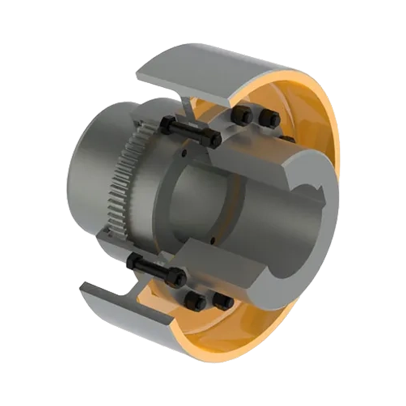
The HCL type elastic pin coupling with brake wheel belongs to the category of flexible couplings with non-metallic elastic elements. Its main structure consists of two coupling halves, an elastic pin assembly, and an integrated brake wheel. The elastic pins connect the coupling components while allowing a controlled degree of flexibility between the driving and driven shafts. The brake wheel provides a dedicated friction surface for a compatible braking device.
Unlike a rigid coupling, which directly transfers shaft misalignment and torsional shocks into the connected equipment, an elastic pin coupling introduces a resilient transmission path. This resilience helps reduce the effect of starting impacts, load fluctuations, and small installation errors. At the same time, the coupling maintains a positive mechanical connection that is suitable for high-torque industrial drives.
The brake wheel is a defining feature of the HCL design. In a conventional arrangement, the coupling and brake disc or brake drum may be installed as separate components. That arrangement can increase axial length, require additional supports, and complicate alignment. By integrating the brake wheel into the coupling structure, the HCL design can simplify the transmission layout and reduce the number of separate components installed on the shaft line.
The product is particularly appropriate for systems in which braking must occur frequently or where controlled stopping is important for safety. Typical examples include lifting mechanisms, hoists, cranes, conveyors, rolling equipment, mining machinery, and port handling systems. In these applications, the coupling is exposed to repeated starts and stops, reversing loads, vibration, and varying torque. The elastic pin structure helps the system manage these operating conditions more smoothly.
2. Working Principle of the HCL Coupling
During operation, the driving shaft rotates one coupling half, while the elastic pins transfer torque to the other coupling half and the driven shaft. The non-metallic pins are positioned between the corresponding holes or connecting surfaces of the coupling halves. When torque is applied, the pins experience controlled elastic deformation. This deformation allows the coupling to transmit power while absorbing part of the impact and vibration generated by the drive system.
The elastic pins also allow the coupling to tolerate limited radial and axial displacement between the connected shafts. Such displacement may result from manufacturing tolerances, foundation movement, thermal expansion, bearing clearance, or minor assembly errors. The coupling does not eliminate the need for correct shaft alignment, but it reduces the sensitivity of the drive to small unavoidable deviations.
As the shaft line rotates, the brake wheel rotates together with the coupling. When the brake is activated, the braking device applies friction or clamping force to the brake wheel surface. The resulting braking torque is transferred through the coupling and shaft line to decelerate or stop the driven equipment. The combined arrangement reduces the need for a separate brake-mounted shaft component.
The brake wheel must be matched with an appropriate braking device, brake lining, braking torque, speed, thermal capacity, and duty cycle. The coupling itself provides the rotating brake surface; complete braking performance depends on the entire brake system, including the actuator, friction material, control system, mounting arrangement, and maintenance condition.
3. Main Technical Characteristics
3.1 Integrated Coupling and Brake Wheel
The most important characteristic of the HCL series is the integration of the brake wheel with the elastic pin coupling. This design can reduce the space required for the transmission assembly and make the layout more orderly. It may also reduce the number of shaft-mounted parts, simplify the connection between the drive and brake system, and support easier access during equipment design and maintenance.
For machinery with restricted installation space, the integrated structure can be more practical than a coupling and brake wheel installed separately. Designers can place the braking function near the transmission connection without adding an independent brake hub or extending the shaft line unnecessarily.
3.2 Non-Metallic Elastic Elements
The elastic pins are manufactured from non-metallic elastic material selected for flexibility, shock absorption, and reliable torque transmission. Compared with a completely rigid connection, the elastic elements help moderate the effects of sudden load changes. They can reduce the transmission of vibration into the motor, gearbox, bearings, and connected machine.
Non-metallic elastic components also provide a relatively simple construction. The coupling does not depend on a complex multi-layer metallic membrane, intricate gear teeth, or lubrication of an internal gear mesh. This can make routine inspection and replacement more straightforward when the elastic pins eventually reach the end of their service life.
3.3 Compensation for Limited Misalignment
Industrial shafts are rarely perfectly aligned under all operating conditions. The HCL coupling is designed to compensate for limited radial and axial misalignment. This capability helps accommodate normal assembly tolerances and moderate changes caused by operating temperature or machine movement.
Misalignment compensation should not be treated as permission to install shafts inaccurately. Excessive misalignment increases elastic deformation, heat generation, wear, and reaction forces. Proper alignment remains essential for achieving the rated service life of the coupling, bearings, brake components, and connected equipment.
3.4 Wide Torque and Speed Range
The HCL product family includes fifteen model sizes, identified from HCL1 through HCL15. Nominal torque ratings range from 560 N·m for HCL1 to 35,500 N·m for HCL14 and HCL15. The permissible speed varies by model and reaches 5,600 r/min for the HCL1 configuration.
This range allows users to select a coupling based on actual torque, speed, bore diameter, inertia, mass, and installation dimensions rather than adapting one limited-size product to every application. Smaller models can be considered for compact drive systems, while larger models provide the capacity required by cranes, heavy conveyors, metallurgy equipment, and other high-load machinery.
3.5 Suitability for Frequent Starting and Stopping
Many industrial machines do not operate at a steady, continuous speed. Hoists accelerate and decelerate repeatedly. Conveyors may start under partial or full load. Metallurgical equipment can experience sudden changes in resistance. Port machinery may require rapid stopping and reversing during positioning operations.
The elastic element helps absorb part of the impact associated with these repeated cycles. The integrated brake wheel supports a compact braking arrangement, while the coupling’s torque capacity provides a mechanical connection suitable for demanding duty. Correct selection must consider the number of starts per hour, acceleration time, braking frequency, peak torque, emergency stopping conditions, and ambient temperature.
4. Selected Technical Parameters
The following table summarizes representative HCL series specifications. The complete selection must be confirmed against the operating torque, speed, shaft dimensions, installation conditions, and applicable technical documentation.
| Model | Nominal Torque (N·m) | Permissible Speed (r/min) | Representative Shaft Bore Range (mm) | Moment of Inertia (kg·m²) | Mass (kg) |
|---|---|---|---|---|---|
| HCL1 | 560 | 5600 | 20–35 | 0.055 | 11 |
| HCL2 | 1250 | 3750 | 30–48 | 0.072 | 14 |
| HCL3 | 1250 | 2430 | 30–48 | 0.313 | 25 |
| HCL4 | 2500 | 2430 | 40–63 | 0.504 | 40 |
| HCL5 | 2500 | 1900 | 40–63 | 1.192 | 59 |
| HCL6 | 3150 | 1900 | 50–75 | 1.402 | 69 |
| HCL7 | 3150 | 1500 | 50–75 | 2.872 | 91 |
| HCL8 | 6300 | 1900 | 60–85 | 1.800 | 88 |
| HCL9 | 6300 | 1500 | 60–85 | 3.582 | 113 |
| HCL10 | 11200 | 1500 | 70–110 | 4.970 | 156 |
| HCL11 | 11200 | 1220 | 70–110 | 9.392 | 187 |
| HCL12 | 16000 | 1220 | 80–125 | 16.430 | 326 |
| HCL13 | 22400 | 1080 | 100–140 | 21.660 | 337 |
| HCL14 | 35500 | 1060 | 110–180 | 29.550 | 458 |
| HCL15 | 35500 | 950 | 110–180 | 41.080 | 504 |
The shaft bore ranges in the table represent the available combinations within each model family. Actual shaft bore selection may be specified through Y-type, J-type, J1-type, or Z-type configurations, depending on the application and required connection arrangement.
The listed moment of inertia and mass are calculated according to the J/Y shaft hole combination and the minimum shaft bore diameter. Actual values may change when a different bore combination, keyway arrangement, or customized configuration is selected.
5. Advantages Compared with Conventional Coupling Arrangements
5.1 More Efficient Use of Installation Space
A separate coupling and brake wheel can require additional shaft length, support spacing, and assembly clearance. The HCL design combines these functions in one unit. This can help reduce the axial footprint of the drive system and make it easier to package the motor, gearbox, brake, and driven machine.
Space efficiency is particularly valuable in crane machinery, hoisting systems, compact mining equipment, and port equipment, where the available frame dimensions are often restricted. A shorter transmission arrangement may also reduce the need for extended shafts and additional bearing supports.
5.2 Reduced Torsional Shock
Rigid couplings transfer torque fluctuations directly through the shaft line. They may be suitable where precise positional rigidity is required, but they provide little protection against shock loads. The HCL coupling introduces a resilient non-metallic connection that can moderate sudden torque changes.
This characteristic can help protect motors, reducers, shafts, bearings, and gear sets from unnecessary impact. It may also improve operating smoothness and reduce vibration-related noise. The level of benefit depends on the elastic pin material, torque profile, alignment, temperature, and overall system design.
5.3 Simplified Braking Layout
With the brake wheel integrated into the coupling, the braking system can be arranged close to the shaft connection. Compared with an independent brake wheel mounted elsewhere, the HCL design can reduce the number of interfaces that must be aligned and inspected.
A simplified layout may assist equipment manufacturers during assembly and servicing. It can also help reduce the risk of errors caused by separate brake hub installation, incorrect axial positioning, or incompatible shaft connections.
5.4 Broad Application Coverage
The HCL series offers a wide range of torque and speed ratings. This makes it more adaptable than a single-size coupling intended for a narrow operating range. Users can select a model according to the actual equipment duty, shaft diameter, brake arrangement, and available space.
The product is suitable for applications ranging from relatively high-speed compact drives to large, slower-speed systems requiring high nominal torque. This flexibility is valuable for original equipment manufacturers, replacement projects, plant modernization, and non-standard machinery design.
5.5 Maintenance-Friendly Elastic Pin Replacement
The non-metallic pins are wear components and should be inspected periodically. When replacement is required, the basic coupling design allows maintenance personnel to focus on the elastic elements rather than replacing the complete coupling assembly in every case.
Actual replacement procedures depend on the equipment layout and coupling model. Before maintenance, the machine must be isolated from all power sources, the brake must be secured, and the shaft line must be prevented from moving. Replacement pins should match the specified material, dimensions, and performance requirements.
6. Manufacturing Process and Quality Approach
The performance of a heavy-duty coupling depends not only on its design but also on the manufacturing accuracy and process control used to produce it. The manufacturing organization behind the HCL series integrates research and development, machining, assembly, testing, and technical service. This integrated approach supports consistent control from product design through final delivery.
6.1 Engineering and Product Development
Coupling design begins with the operating requirements of the application. Engineers must consider nominal torque, peak torque, rotational speed, shaft diameter, bore length, misalignment, braking torque, temperature, load cycles, and environmental conditions. These parameters influence the dimensions of the coupling halves, brake wheel, elastic pins, fasteners, and shaft connection.
Design work also involves checking the balance of the rotating assembly, the stiffness of the brake wheel, the contact condition of the elastic pins, and the available installation space. For customized projects, the company can develop non-standard coupling solutions according to customer drawings, equipment interfaces, or specific operating conditions.
6.2 Material and Component Control
The metallic coupling components and brake wheel require suitable material selection, dimensional stability, and surface quality. The brake wheel must provide a reliable running surface for the selected braking device. The elastic pins must maintain their mechanical properties under repeated deformation and the temperature range of the application.
Incoming inspection of materials and purchased components is an important part of quality control. Dimensional checks, visual inspection, material verification, and documentation review help ensure that the production process begins with qualified inputs. Consistent material control is particularly important for large coupling components that must withstand high torque and repeated loading.
6.3 Precision Machining
Coupling components require accurate bore dimensions, concentricity, flange geometry, bolt-hole positioning, and brake wheel runout. Precision machining equipment is used to process the rotating parts and connection surfaces according to engineering drawings and process specifications.
Accurate machining helps maintain the intended shaft fit and reduces the possibility of excessive imbalance. It also supports proper load distribution through the elastic pins and minimizes additional forces caused by eccentricity. For large models, machining quality is especially important because small geometric errors can produce significant dynamic forces at operating speed.
6.4 Brake Wheel Surface Treatment and Finishing
The brake wheel surface is a functional interface between the coupling and the braking device. Its roundness, surface condition, dimensional accuracy, and resistance to wear influence brake performance. Appropriate surface treatment and finishing can support stable friction contact and improve durability during repeated braking cycles.
The brake wheel should be protected from oil, grease, paint overspray, excessive corrosion, and contamination that could affect friction. During production, surface inspection and dimensional verification help ensure that the brake wheel is suitable for integration into the completed coupling assembly.
6.5 Assembly and Inspection
Assembly involves fitting the coupling halves, installing elastic pins, checking the brake wheel, and verifying the specified bore and keyway arrangement. Fasteners must be installed with the correct grade, tightening procedure, and retention method. The elastic elements must be positioned correctly so that the load is distributed evenly during operation.
Inspection may include dimensional checks, visual examination, rotating runout verification, balance checks, and functional assessment of the assembled component. The exact inspection plan depends on the model, order requirements, application, and applicable technical standard.
6.6 Production Facilities
The manufacturer operates a new workshop covering approximately 16,463.52 square meters. The facility includes a heavy workshop of about 5,500 square meters, a precision workshop of approximately 4,600 square meters, an office building and gymnasium, a dining hall, a warehouse, and supporting roads, green areas, and parking facilities.
This production layout provides space for handling both large industrial coupling components and precision-machined parts. The separation of heavy and precision work areas can support more organized manufacturing, material movement, equipment deployment, and inspection activities.
7. Manufacturing Strengths and Supplier Capability
The company behind the HCL coupling has experience in the design and manufacture of multiple coupling categories, including toothed couplings, elastic sleeve pin couplings, elastic pin couplings, gear couplings with elastic pins, universal couplings, tire couplings, jaw couplings, star couplings, diaphragm couplings, drum couplings, grid couplings, Oldham couplings, flange couplings, clip-shell couplings, roller chain couplings, safety couplings, and customized non-standard couplings.
This product breadth is valuable because different machines require different transmission solutions. A customer may need a flexible coupling for one drive, a safety coupling for another, and a customized connection for a third system. A manufacturer with experience across several coupling technologies can compare design alternatives and recommend a solution according to torque, speed, misalignment, maintenance, and environmental requirements.
The company combines research and development, manufacturing, sales, and technical support. Its stated strengths include complete specifications, custom design capability, testing facilities, quality control, pre-sale engineering support, non-standard design services, and after-sale assistance. These capabilities are relevant to the HCL product because the correct coupling cannot be selected by torque alone.
For industrial projects, supplier responsiveness is also important. Customers may require dimensional drawings, shaft bore confirmation, brake wheel dimensions, material information, replacement pin specifications, delivery coordination, or installation guidance. A supplier that can support these requirements reduces the risk of delays between design approval, procurement, installation, and commissioning.
The company reports that its products comply with international standards and certifications such as ISO 9001. Quality management certification does not replace product-specific engineering verification, but it indicates that documented procedures are used to manage production and quality activities. Customers should still review the relevant technical documents and inspection requirements for each project.
8. Application Areas
8.1 Lifting and Hoisting Equipment
Lifting equipment requires reliable torque transmission and controlled braking. Cranes, hoists, winches, and lifting platforms may experience high starting torque, repeated acceleration, sudden load changes, and emergency stopping requirements. The HCL coupling can combine a flexible shaft connection with a brake wheel in a compact arrangement.
When used in lifting machinery, selection must account for the lifted load, drum diameter, reeving arrangement, motor power, gearbox ratio, duty classification, starting frequency, braking torque, and emergency stop conditions. The coupling must be integrated with the complete mechanical and safety design of the lifting system.
8.2 Metallurgical Machinery
Metallurgical equipment often operates in demanding environments involving heat, dust, vibration, heavy loads, and frequent cycling. Rolling mills, transfer tables, coilers, shears, material handling systems, and furnace-related machinery may require robust couplings with shock absorption capability.
The HCL design can be considered where the drive requires a combination of high torque transmission, limited misalignment compensation, and braking. Environmental temperature and radiation should be checked carefully because elastic materials have specific operating limits.
8.3 Mining Equipment
Mining systems frequently operate under variable loads and difficult maintenance conditions. Conveyors, crushers, hoists, feeders, and material handling equipment may generate substantial torque fluctuation and impact loading. A flexible elastic pin coupling can help reduce the direct transfer of those disturbances through the drive train.
For mining applications, users should consider dust protection, accessibility, inspection intervals, available replacement components, and the consequences of coupling failure. Where the machine presents a significant safety risk, the coupling should be included in the overall preventive maintenance and emergency response plan.
8.4 Port and Marine-Terminal Equipment
Port machinery must frequently accelerate, decelerate, position, and hold loads. Ship loaders, stacker-reclaimers, winches, conveyors, and crane mechanisms may benefit from a compact coupling and braking arrangement. The brake wheel supports controlled stopping, while the elastic pins help manage starting and stopping impacts.
Port environments may expose equipment to moisture, salt-laden air, corrosion, and fluctuating temperatures. Protective coatings, sealing, storage, lubrication of adjacent components, and regular brake surface inspection should be included in the maintenance plan.
8.5 Water and General Industrial Equipment
The company’s products are also used in water equipment, paper equipment, general industrial drives, and other power transmission systems. The HCL coupling may be considered for pumps, conveyors, auxiliary drives, and machinery requiring an integrated braking function, provided the speed, torque, environment, and brake arrangement meet the product requirements.
9. Coupling Selection Guidelines
9.1 Calculate Operating Torque
Selection should begin with the actual transmitted torque rather than motor power alone. For a rotating system, torque is related to power and speed. The operating torque should be multiplied by an appropriate service factor that reflects shock loading, starting conditions, reversing, braking, duty cycle, and the driven machine characteristics.
Peak torque is equally important. A coupling that appears adequate for average running torque may be undersized if the machine produces high starting, stall, reversing, or emergency braking torque. The selected nominal torque should provide an appropriate margin above the calculated working requirement.
9.2 Check Speed and Dynamic Conditions
The selected model must operate below its permissible speed. Rotational speed, coupling balance, brake wheel runout, shaft eccentricity, and installation accuracy all influence dynamic performance. High-speed applications require particular attention to concentricity, balance, and correct shaft fit.
The HCL1 model has the highest listed permissible speed of 5,600 r/min. Larger models generally have lower permissible speeds because of their greater dimensions, mass, and operating torque. Users should not assume that a larger torque rating automatically permits high-speed operation.
9.3 Confirm Shaft Bore and Length
The shaft bore must match the driving and driven shaft diameters, keyways, and connection types. The available shaft bore length must also be sufficient for the shaft extension and key engagement. A correct bore diameter with insufficient engagement length can create an unsafe connection.
Available HCL configurations include Y-type, J-type, J1-type, and Z-type shaft hole arrangements. The correct configuration depends on the shaft design, installation method, and required disassembly procedure. Shaft tolerances should be reviewed before manufacturing or ordering the coupling.
9.4 Evaluate Braking Requirements
The coupling selection must be coordinated with the brake. Important considerations include required braking torque, braking speed, stopping time, brake wheel diameter, friction material, heat generation, emergency braking frequency, and the thermal capacity of the complete brake assembly.
The brake wheel should not be treated as an isolated component. Brake performance depends on the interaction among the brake wheel, brake lining, actuator, control logic, machine inertia, and load. The stopping distance and stopping time must be evaluated for the complete equipment system.
9.5 Consider Environmental Conditions
Temperature, moisture, dust, chemicals, outdoor exposure, corrosive atmosphere, and installation altitude may affect coupling life. Non-metallic elastic components are particularly sensitive to compatibility with temperature and chemicals. The correct elastic material should be confirmed for the operating environment.
Where the coupling is installed outdoors or in a corrosive area, suitable protective measures should be used. These may include surface coatings, guards, drainage provisions, sealing arrangements, and scheduled inspection of the brake wheel and fasteners.
10. Installation and Maintenance Recommendations
Before installation, inspect the coupling, brake wheel, elastic pins, fasteners, shaft surfaces, keyways, and mounting faces. Remove dirt, burrs, rust, and protective materials that could prevent correct seating. Confirm that the actual shaft dimensions correspond to the approved drawing.
Align the shafts carefully in the radial and axial directions. The coupling’s flexibility is intended to accommodate limited operating displacement, not to compensate for poor installation. Excessive misalignment may shorten the life of the elastic pins and increase the forces transmitted to bearings and connected equipment.
Install keys, bolts, locking components, and other hardware according to the specified dimensions and tightening requirements. Do not substitute fasteners without engineering approval. Check that the brake wheel rotates freely and that the brake does not remain in contact when released.
After installation, rotate the assembly manually when possible to check for interference, abnormal resistance, or eccentric movement. Conduct a low-speed test before full-load operation. Monitor vibration, noise, brake release, brake engagement, elastic pin movement, and coupling temperature during commissioning.
Routine inspections should look for cracked, deformed, hardened, softened, or excessively worn elastic pins. Inspect the brake wheel for scoring, uneven wear, excessive runout, contamination, and thermal damage. Check fasteners for looseness and confirm that shaft connections remain secure.
Replacement of elastic pins should be performed as a complete maintenance activity rather than as an isolated part change. The coupling should be cleaned, the cause of abnormal wear should be investigated, and alignment should be rechecked. If wear is concentrated on one side of the pins, misalignment or uneven loading may be present.
Maintenance records should include inspection dates, operating hours, brake adjustments, pin replacement, measured alignment, abnormal events, and any changes in machine duty. These records help establish a predictive maintenance schedule and support long-term reliability.
11. Customization and Non-Standard Solutions
Although the HCL series includes a broad range of standard models, industrial equipment frequently involves special dimensions or unusual operating conditions. Customized requirements may include a special shaft bore, modified shaft bore length, alternative keyway, non-standard brake wheel dimensions, altered mounting dimensions, special coating, different material requirements, or adaptation to an existing machine.
Customization should begin with complete technical information. Useful data includes motor power, operating speed, calculated torque, peak torque, shaft diameters, shaft extensions, key dimensions, center distance, brake type, brake torque, ambient temperature, duty cycle, installation orientation, and available drawings.
The manufacturer’s experience with multiple coupling types supports engineering comparison when a standard HCL model is not sufficient. In some cases, a different flexible coupling category may be more suitable. In other cases, a modified HCL coupling can satisfy the equipment interface while preserving the advantages of an integrated brake wheel and elastic pin connection.
All customized dimensions should be reviewed and approved before production. Special designs may require additional calculations, drawings, material confirmation, balance requirements, inspection procedures, and prototype or sample verification.
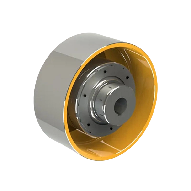
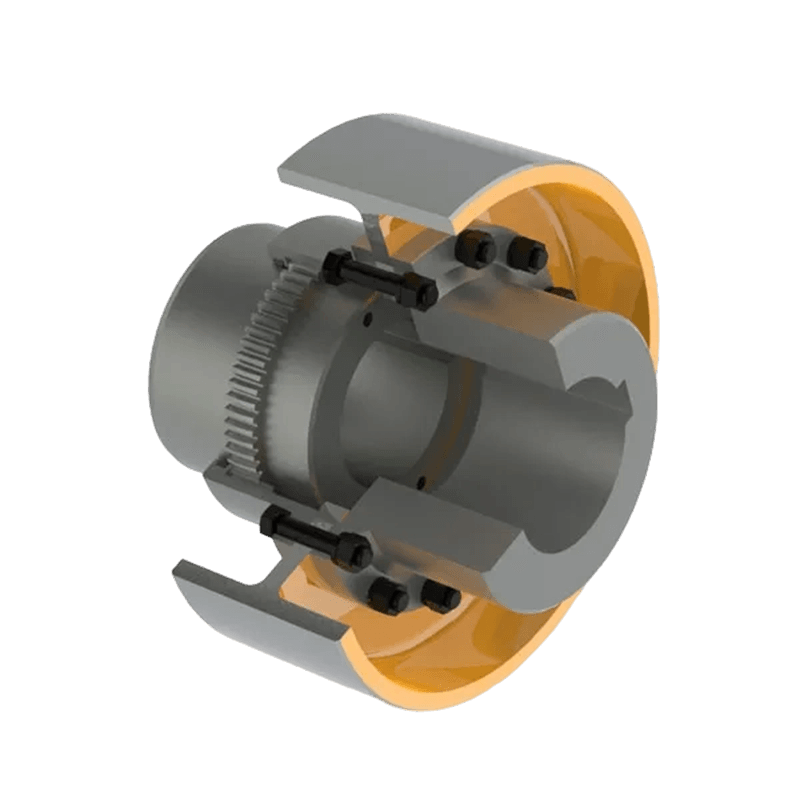
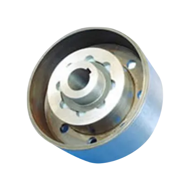
HCL type elastic pin coupling with brake wheel (Q/YZ31002X-2018)
12. Why Choose This Coupling for Heavy-Duty Transmission
The HCL type elastic pin coupling with brake wheel addresses several common challenges in industrial transmission design at the same time. It provides flexible torque transmission, limited misalignment compensation, shock absorption, and a dedicated braking surface. The combination is especially useful where the drive experiences frequent starts and stops and where installation space is restricted.
Compared with a rigid coupling, the HCL design offers greater ability to absorb operating disturbances. Compared with a coupling without an integrated brake wheel, it can provide a more compact braking arrangement. Compared with a narrow product family, its fifteen model sizes offer a broad selection of torque, speed, bore, mass, inertia, and dimensional characteristics.
The manufacturing organization adds further value through engineering support, production experience across many coupling categories, precision and heavy machining facilities, quality management, testing capability, and customization support. These strengths help customers move beyond a simple catalog purchase toward a complete coupling selection and application solution.
For demanding industries, product reliability is influenced by the entire supply chain. Accurate drawings, responsive technical communication, controlled manufacturing, correct inspection, suitable packaging, installation guidance, spare parts availability, and after-sales support all contribute to successful operation. The company’s integrated R&D, manufacturing, sales, and service structure is intended to support these requirements.
13. Frequently Asked Questions
What is an HCL elastic pin coupling with brake wheel?
It is a flexible shaft coupling that uses non-metallic elastic pins to transmit torque and compensate for limited shaft misalignment, while incorporating a brake wheel into the coupling assembly. It is manufactured according to the Q/YZ31002X-2018 technical standard.
What is the main advantage of integrating the brake wheel?
Integration can reduce installation space and simplify the shaft-line arrangement by combining coupling and brake-wheel functions in one assembly. It may also reduce the number of separate hubs and alignment interfaces required in the transmission system.
What torque range does the HCL series cover?
The listed nominal torque range is from 560 N·m to 35,500 N·m. The correct model must be selected according to working torque, peak torque, service factor, speed, shaft dimensions, and operating conditions.
What is the highest permissible speed in the series?
The highest listed permissible speed is 5,600 r/min for the HCL1 model. Permissible speed varies by model and is generally lower for larger, higher-torque coupling sizes.
Can the coupling compensate for shaft misalignment?
Yes. The elastic pin structure is designed to accommodate limited radial and axial shaft displacement. However, it should not be used to compensate for excessive misalignment. Accurate installation remains essential for reliable service.
Where is this coupling commonly used?
Common application areas include lifting equipment, cranes, hoists, metallurgy machinery, mining equipment, port machinery, conveyors, water equipment, paper machinery, and other heavy-duty industrial drives requiring flexible transmission and braking.
Do the elastic pins require regular inspection?
Yes. The pins should be inspected for wear, cracking, deformation, hardening, softening, and uneven loading. Inspection frequency depends on operating hours, load conditions, temperature, vibration, and the number of starts and stops.
Can the HCL coupling be customized?
Customization may be available for shaft bores, bore lengths, keyways, mounting dimensions, brake wheel dimensions, coatings, materials, and other non-standard requirements. Complete equipment and interface information should be supplied for engineering review.
How should the brake wheel be maintained?
The brake wheel should be kept free from oil, grease, dirt, and other contamination. Inspect it for scoring, uneven wear, thermal damage, corrosion, and excessive runout. Brake adjustment and friction-material maintenance should follow the requirements of the complete brake system.
Are the listed mass and inertia values universal for every configuration?
No. The listed values are calculated according to the J/Y shaft hole combination and the minimum shaft hole diameter. Actual mass and moment of inertia may vary with the selected bore combination and customized configuration.
What information is needed for product selection?
Important information includes transmitted power, speed, working and peak torque, shaft diameters, shaft extensions, keyway dimensions, alignment conditions, brake torque, braking frequency, ambient temperature, installation space, duty cycle, and applicable safety requirements.
14. Conclusion
The HCL type elastic pin coupling with brake wheel is a practical solution for industrial drive systems that require flexible torque transmission and integrated braking. Its non-metallic elastic pins help absorb shock, accommodate limited radial and axial displacement, and improve the mechanical behavior of systems exposed to changing loads. Its integrated brake wheel supports a compact transmission layout and can simplify the relationship between the coupling and braking equipment.
With nominal torque ratings from 560 N·m to 35,500 N·m and permissible speeds up to 5,600 r/min, the series covers a broad range of industrial requirements. Fifteen model sizes and multiple shaft bore configurations provide flexibility for new equipment, replacement projects, and customized machinery.
The product’s value is strengthened by the manufacturer’s integrated capabilities in research and development, heavy and precision machining, assembly, inspection, quality management, customized engineering, and technical service. These capabilities support consistent production and help users select a coupling that matches the complete mechanical system rather than relying on nominal torque alone.
For lifting, metallurgy, mining, port, water, paper, and general industrial applications, the HCL coupling can offer a balanced combination of compact design, elastic shock absorption, misalignment tolerance, braking integration, and heavy-duty transmission capability. Correct selection, alignment, brake coordination, installation, and preventive maintenance remain essential to achieving reliable long-term performance.
References
Q/YZ31002X-2018, Technical Standard for HCL Type Elastic Pin Couplings with Brake Wheels.
Manufacturer-provided HCL Type Elastic Pin Coupling with Brake Wheel Technical Parameters and Main Dimensions.
Manufacturer-provided Product and Company Information for Industrial Couplings and Customized Transmission Components.
General engineering principles for flexible couplings, elastic torque transmission, shaft alignment, and industrial braking systems.
General maintenance practices for rotating machinery, flexible couplings, brake wheels, and non-metallic elastic components.
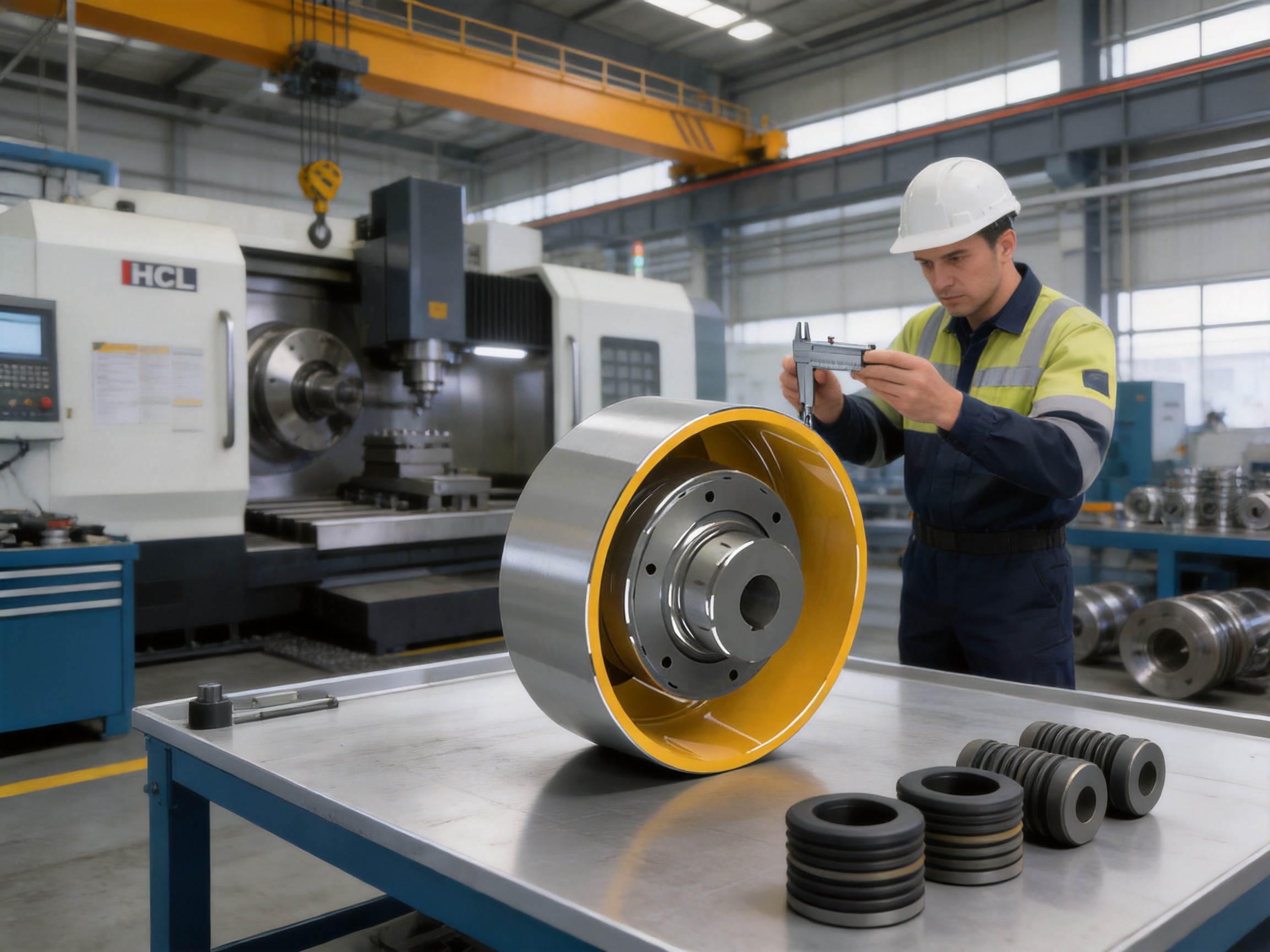
Product: HCL type elastic pin coupling with brake wheel (Q/YZ31002X-2018)

- Quick Links
- About
- Products
- Our Service
- News & Events
- Contact
- Products Series
- Flexible Couplings with Non-Elastic Elements
- Flexible Couplings with Metal Elastic Elements
- Flexible Couplings with Non-Metallic Elastic Elements
- Safety Coupling
- Rigid Coupling
- Contact Us
- Tel : +86 511 8572 3800 +86 511 8572 3900
- Mobile : +86 15106109009
- Email : sales@couplingzy.com
- Add:No.1 Zhongye Yingbin Avenue, Gaozi Street, Dantu Economic Development Zone, Zhenjiang City, Jiangsu Province, China.


