:+86 15106109009
:sales@couplingzy.com


 English
  русский
  Español
  عربى
عربى  Português
  Deutsch
  Türk
Türk  Indonesia

Drum Gear Coupling with Brake Disc: Design, Performance, Manufacturing, and Industrial Applications
Content
- 1 1. Role of a Drum Gear Coupling in Industrial Transmission Systems
- 2 2. Product Overview and Series Configuration
- 3 3. Enhanced Misalignment Compensation
- 4 4. Brake Disc Integration and Load Distribution
- 5 5. Torque Capacity and Speed Performance
- 6 6. Structural Materials and Mechanical Reliability
- 7 7. Manufacturing Strength and Quality Control
- 8 8. Advantages Compared with Conventional Couplings
- 9 9. Application in Lifting and Port Machinery
- 10 10. Application in Metallurgical and Mining Equipment
- 11 11. Application in Water Treatment, Paper, and Conveyor Systems
- 12 12. Lubrication and Maintenance
- 13 13. Installation Recommendations
- 14 14. Coupling Selection Method
- 15 15. Why Manufacturing Capability Matters to Buyers
- 16 16. Limitations and Engineering Considerations
- 17 17. Recommended Inspection Schedule
- 18 18. Q&A: Common Questions About the GAP Drum Gear Coupling
- 18.1 Q1: What type of coupling is the GAP product?
- 18.2 Q2: What is the main purpose of the brake disc?
- 18.3 Q3: Can the coupling rotate in both directions?
- 18.4 Q4: What is the torque range?
- 18.5 Q5: What is the highest listed speed?
- 18.6 Q6: How is axial movement accommodated?
- 18.7 Q7: What does the dimension “e” mean?
- 18.8 Q8: What bore combinations are available?
- 18.9 Q9: What is the braking torque limit?
- 18.10 Q10: Does the coupling require lubrication?
- 18.11 Q11: Is customization available?
- 18.12 Q12: Which industries commonly use this coupling?
- 19 19. Conclusion
- 20 References
- 21 Product: GAP Drum gear coupling with brake disc (Q/YG 12008X-2018)
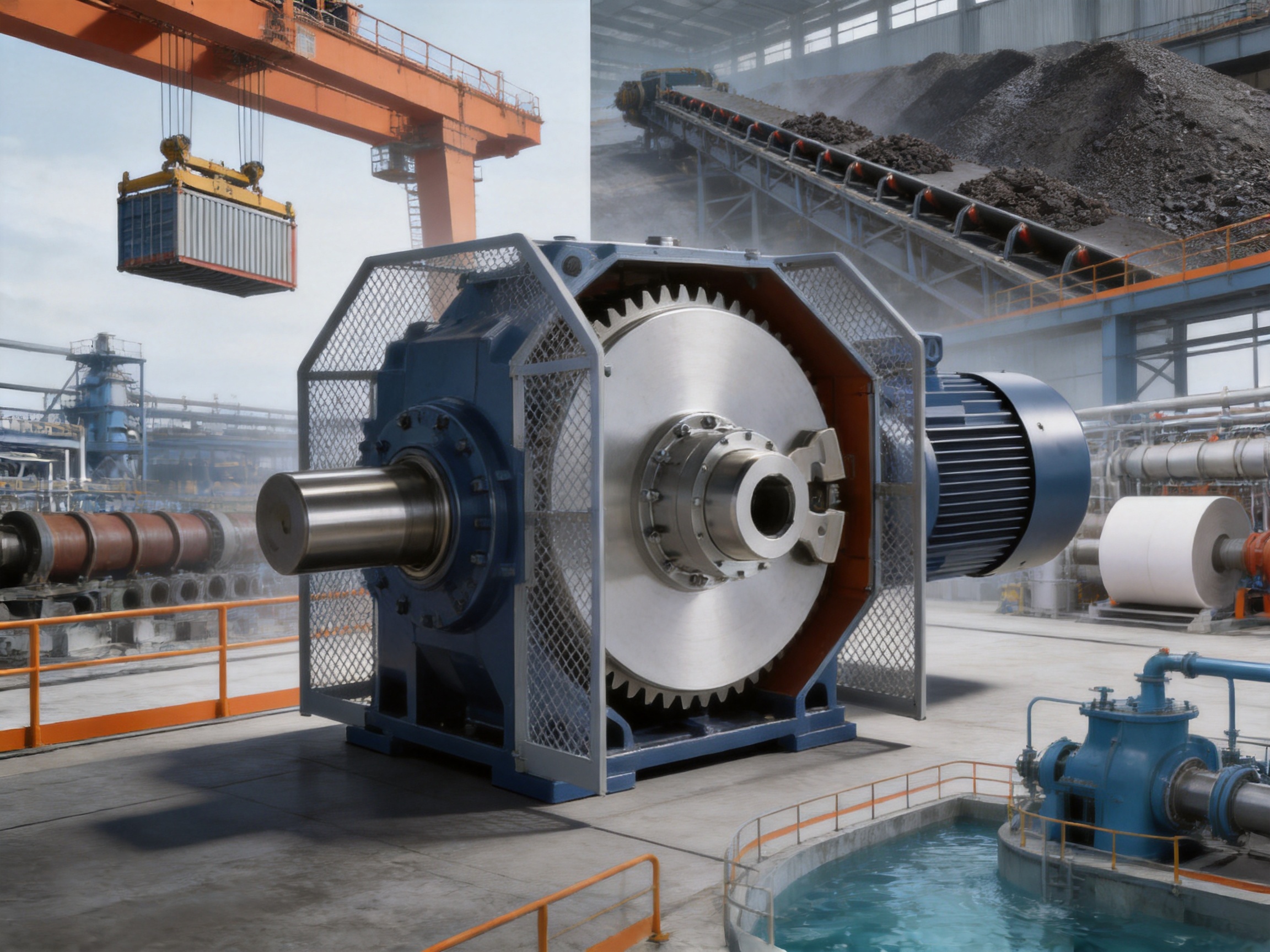
Drum gear couplings with brake discs are engineered for transmission systems that must combine high torque capacity, controlled braking, reliable misalignment compensation, and long operating life. The GAP drum gear coupling with brake disc, manufactured according to Q/YG 12008X-2018, is designed for demanding industrial equipment such as lifting machinery, port cranes, metallurgical production lines, mining systems, paper machines, conveyors, and water-treatment equipment.
Unlike a basic gear coupling, this product integrates a brake disc into the coupling structure. The result is a compact transmission and braking arrangement that can transfer power while supporting frequent starting, stopping, reversing, and emergency braking operations. Its crowned gear teeth, enlarged internal gear sleeve, multiple bore configurations, and broad size range make it suitable for applications in which shaft alignment, braking loads, and severe working conditions must all be considered together.
The GAP series includes models from GAP1 through GAP14. Nominal torque ratings extend from 630 N·m to 112,000 N·m, while allowable speeds reach 4,000 r/min on smaller models. The series is therefore capable of serving both relatively high-speed machinery and large, heavy-duty transmission systems.
1. Role of a Drum Gear Coupling in Industrial Transmission Systems
A coupling connects two shafts so that torque can pass from a driving machine to a driven machine. In real equipment, however, the two shafts are rarely aligned perfectly. Installation tolerances, foundation settlement, thermal expansion, bearing wear, manufacturing variation, and structural deformation can produce angular, radial, or axial displacement.
A rigid coupling cannot accommodate these movements without transmitting additional forces into the shafts, bearings, gearboxes, and connected machines. A flexible coupling is therefore required when the transmission system must tolerate controlled misalignment while maintaining torque transmission.
Gear couplings use the meshing action of external and internal gear teeth. The teeth transmit high torque through a relatively compact structure, while crowned tooth profiles permit a degree of angular and radial movement. Drum gear couplings are a specialized form of gear coupling designed to provide enhanced compensation capability and stable operation under heavy loading.
When a brake disc is added, the coupling becomes an important part of the stopping system. The coupling must not only transmit the operating torque but also withstand braking torque, vibration, thermal effects, and repeated load reversals. The brake disc mounting position and the load path through the half coupling are especially important because braking can create transient loads considerably higher than normal running loads.
2. Product Overview and Series Configuration
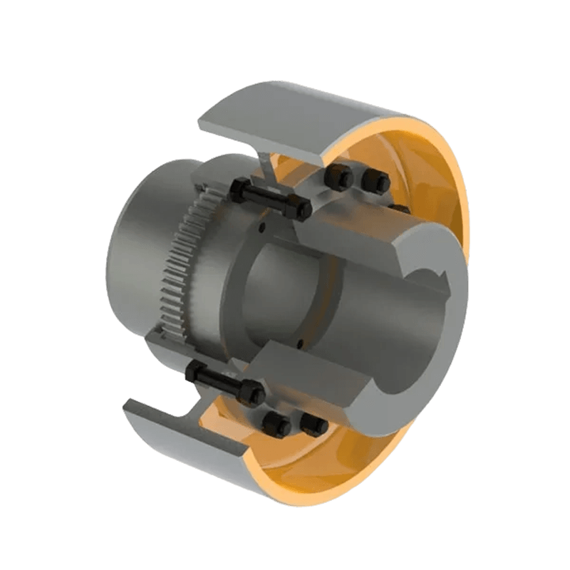
The GAP drum gear coupling with brake disc is a flexible coupling with non-elastic elements. Its primary flexible action is obtained through gear-tooth engagement rather than through rubber, polyurethane, spring, or metallic membrane elements. This construction gives the coupling high torque density and makes it suitable for high-load machinery.
The series is available in fourteen principal sizes:
| Model range | GAP1 to GAP14 |
| Nominal torque range | 630 N·m to 112,000 N·m |
| Maximum listed allowable speed | Up to 4,000 r/min |
| Brake disc diameter range | Approximately 315 mm to 1,000 mm |
| Maximum listed bore diameter | Up to 220 mm |
| Rotation direction | Clockwise and counterclockwise |
| Available bore combinations | Y-Y, J1-J1, Z-Z, Z1-J1, and Y-J1 combinations subject to model selection |
| Braking design limit | Tm ≤ 2Tn |
| Applicable standard | Q/YG 12008X-2018 |
The exact bore range, shaft length, brake disc diameter, mass, and moment of inertia depend on the selected model and configuration. Before ordering, the customer should provide shaft diameters, shaft extensions, operating speed, drive power, braking torque, duty cycle, ambient conditions, and installation constraints.
3. Enhanced Misalignment Compensation
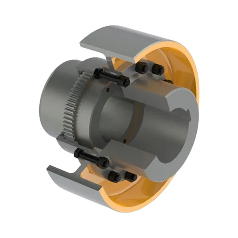
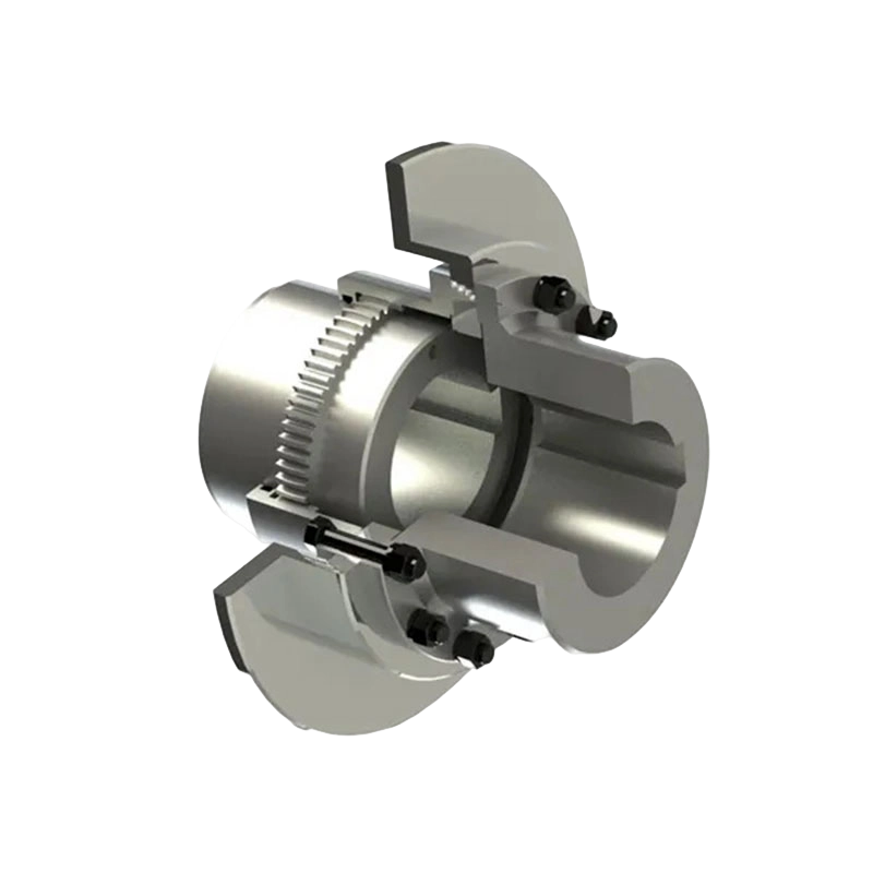
One of the defining features of the GAP design is its wider internal gear sleeve. Compared with conventional gear coupling structures, the enlarged sleeve provides greater effective tooth engagement length and improved axial displacement compensation. This is valuable in equipment where the connected shafts can move relative to one another during operation.
Axial movement may be caused by thermal expansion, shaft movement within bearings, changes in equipment loading, or the use of an intermediate shaft. If the coupling has insufficient axial freedom, the movement can create thrust forces and additional gear-tooth pressure. These forces may accelerate wear and increase the load on bearings and connected equipment.
The wider internal sleeve gives the crowned gear teeth more working space during axial movement. The coupling can continue transmitting torque while accommodating the designed displacement, provided that installation alignment and operating limits remain within specification.
Misalignment compensation does not eliminate the need for accurate installation. A flexible coupling should never be used to correct excessive shaft misalignment. Correct alignment reduces tooth sliding, lowers vibration, improves grease-film conditions, and extends the service life of the entire drive. The coupling is intended to absorb normal operating displacement and installation tolerance, not to replace proper shaft alignment.
3.1 Angular and Radial Movement
Crowned gear teeth are rounded across the tooth face. This geometry allows the contact position to shift as the connected shafts operate at a small angular displacement. Compared with straight-sided teeth, crowned teeth reduce edge loading and help distribute contact pressure more evenly.
During operation, the tooth contact pattern changes as the coupling compensates for movement. The crowned profile helps prevent concentrated contact at the tooth edge, which is a common cause of pitting, scuffing, and premature failure in poorly aligned gear couplings.
Radial and angular compensation are closely related in a practical transmission system. A small offset between shafts can produce angular movement within the coupling, particularly when the distance between shaft supports is large. The GAP structure is intended to maintain effective gear engagement while accommodating these conditions.
3.2 Axial Displacement
Axial displacement is particularly important when the GAP coupling is paired with GBZ and GAZ couplings and an intermediate shaft. In such arrangements, the coupling must allow the intermediate shaft to move without causing excessive axial constraint.
The dedicated dimension marked “e” also supports maintenance access. This dimension provides the clearance required to replace seals without completely dismantling the transmission system. The feature reduces service time and can be especially useful in large production lines where removing an intermediate shaft would require extensive lifting and alignment work.
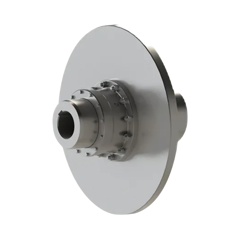
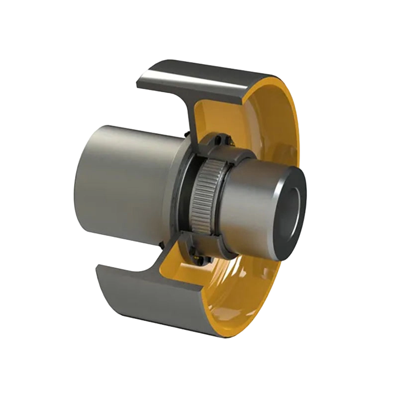
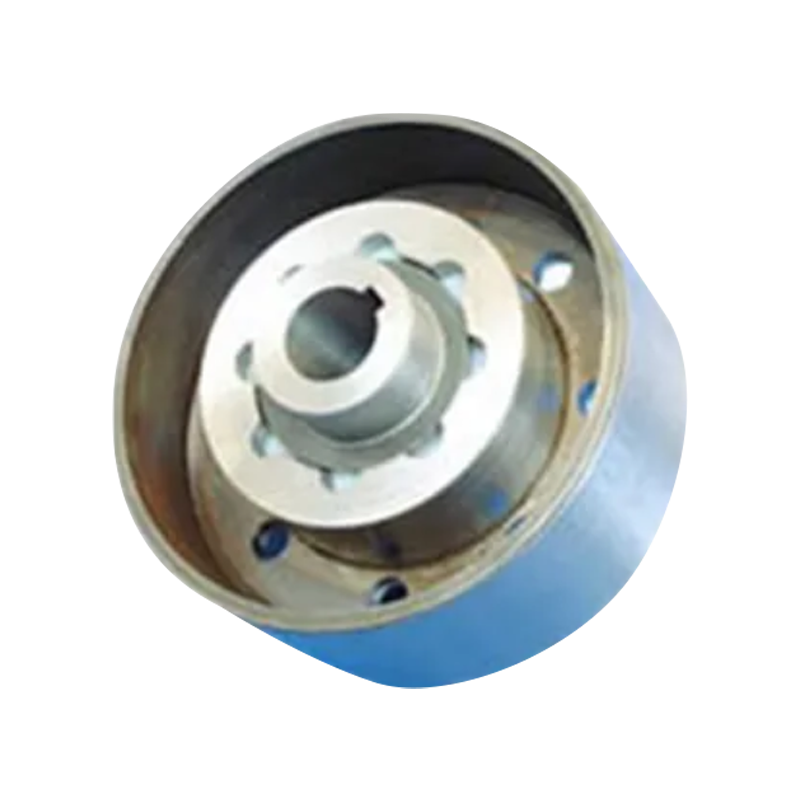
GAP Drum gear coupling with brake disc (Q/YG 12008X-2018)
4. Brake Disc Integration and Load Distribution
The integrated brake disc is mounted directly to the half coupling. This arrangement is more than a convenient packaging choice. It establishes a clear load path for braking forces and allows the half coupling to absorb the weight of the disc as well as the vibration and transient loads generated during braking.
When a brake is applied, the disc experiences frictional force. That force creates braking torque, while the disc mass creates an additional rotating inertia. If the disc is mounted in a way that causes excessive bending or eccentric loading on the gear sleeve, the tooth engagement can become unstable. The GAP design places the disc on the half coupling so that the coupling structure supports these loads directly.
In a typical configuration, the GAP coupling may be combined with GBZ and GAZ couplings, with the intermediate shaft connected through the external gear sleeve end. This arrangement allows the brake disc to work as part of a coordinated transmission system rather than as an isolated component.
4.1 Improved Gear-Tooth Engagement During Braking
Braking creates a rapid change in torque. Depending on the application, the coupling may experience acceleration torque during startup, steady operating torque during production, and braking torque during stopping. The transition between these states can generate shock loading and vibration.
By allowing the half coupling to support the disc mass and braking reaction, the design helps stabilize the relative position of the gear teeth. More stable tooth engagement reduces the likelihood of localized tooth impact, edge contact, and abnormal sliding. This contributes to longer gear-tooth life and more consistent braking performance.
The product specification states that maximum braking torque must not exceed twice the nominal torque:
Tm ≤ 2Tn
This requirement provides a defined safety boundary for selecting the coupling. It also reminds engineers that the coupling must be selected according to braking duty, not only according to the motor’s continuous running torque.
4.2 Braking Torque and Safety Margin
Nominal torque is the reference torque capacity associated with normal power transmission. Braking torque is a separate design parameter and may be considerably higher than the operating torque during a short stopping event. A correct selection must consider the actual brake torque, stopping time, load inertia, frequency of braking, direction changes, and any shock factor required by the application.
For example, a drive with moderate continuous torque may still require a larger coupling if it stops a high-inertia load frequently. Similarly, a crane or hoist may generate substantial transient torque when a suspended load starts or stops. The coupling should be checked against both the steady-state and transient conditions.
5. Torque Capacity and Speed Performance
The GAP series covers a wide torque range. GAP1 is rated at a nominal torque of 630 N·m and has a listed allowable speed of up to 4,000 r/min. At the opposite end of the range, GAP14 provides a nominal torque rating of 112,000 N·m with an allowable speed of 1,200 r/min.
This broad range allows users to standardize the coupling concept across different equipment sizes. Smaller models can be applied to compact, faster rotating drives, while larger models serve heavy-duty machines that demand high torque and large shaft bores.
| Model | Nominal torque | Allowable speed | Typical design emphasis |
| GAP1 | 630 N·m | 4,000 r/min | Compact, high-speed transmission |
| GAP2 | 1,120 N·m | Model data to be confirmed during selection | Light industrial drives |
| GAP3 | 2,240 N·m | 3,550 r/min | Medium-speed machinery |
| GAP4 | 3,550 N·m | 2,500 r/min | General heavy industrial use |
| GAP5 | 5,000 N·m | 2,500 r/min | Braked production equipment |
| GAP6 | 7,100 N·m | 2,000 r/min | Higher-load machinery |
| GAP7 | 10,000 N·m | 1,700 r/min | Heavy transmission systems |
| GAP8 | 14,000 N·m | 1,700 r/min | Large industrial drives |
| GAP9 | 18,000 N·m | 1,600 r/min | High-torque equipment |
| GAP10 | 31,500 N·m | 1,600 r/min | Large braking and drive systems |
| GAP11 | 40,000 N·m | 1,400 r/min | Heavy-duty industrial machinery |
| GAP12 | 56,000 N·m | 1,400 r/min | Very high torque applications |
| GAP13 | 80,000 N·m | 1,400 r/min | Large-scale transmission systems |
| GAP14 | 112,000 N·m | 1,200 r/min | Maximum series torque capacity |
The values in the table are product-family reference values. Final allowable speed may depend on bore configuration, balance grade, installation arrangement, lubrication, temperature, and actual operating conditions. Engineering confirmation is recommended before production use.
6. Structural Materials and Mechanical Reliability
A drum gear coupling operates under a combination of torsional stress, tooth contact stress, bending effects, vibration, and environmental contamination. The material selection and heat-treatment process therefore have a direct effect on product life.
The gear sleeves and hubs should be manufactured from suitable engineering steels capable of resisting tooth wear and repeated torque reversals. Depending on the required duty, processes may include forging, precision machining, gear hobbing or shaping, tooth crowning, heat treatment, grinding, and dimensional inspection.
Heat treatment is particularly important for gear components. A properly controlled process can increase surface hardness and wear resistance while preserving sufficient core toughness. Excessive hardness without adequate toughness can make teeth vulnerable to impact failure, while insufficient hardness can result in rapid wear, plastic deformation, or pitting.
Precision machining is required for the bore, keyway, flange face, gear pitch diameter, and sealing surfaces. Concentricity between the shaft bore and gear teeth affects dynamic balance and load distribution. The brake disc mounting surface must also be accurately machined so that disc runout remains within the required limit.
6.1 Gear-Tooth Manufacturing
Gear-tooth accuracy is central to coupling performance. The tooth geometry must provide sufficient clearance for lubrication and misalignment while maintaining reliable torque transmission. The crowned profile must be controlled consistently across the tooth width.
Manufacturing inspection may include tooth thickness measurement, pitch and runout checks, profile verification, surface hardness testing, and visual inspection for grinding burns, cracks, or other defects. For large couplings, inspection equipment must accommodate substantial component dimensions without compromising measurement accuracy.
6.2 Brake Disc Manufacturing
The brake disc must have adequate strength and dimensional stability during repeated braking. Its flatness, parallelism, thickness, mounting-hole position, and radial runout affect brake response and lining wear.
Because the brake disc rotates with the coupling, unbalanced mass can create vibration. Dynamic balancing is therefore important, especially for high-speed models. The required balancing level depends on rotational speed, disc diameter, shaft arrangement, and customer specifications.
7. Manufacturing Strength and Quality Control
Advanced manufacturing is essential for producing large, high-precision couplings. A reliable supplier should be able to control the complete process from engineering design and material procurement to machining, heat treatment, assembly, testing, packaging, and technical support.
The manufacturer of the GAP series integrates research and development, production, and sales. Its manufacturing facilities include a heavy workshop, precision workshop, office and engineering areas, warehouse capacity, and dedicated testing resources. This combination supports both standard product production and customized coupling development.
A heavy workshop is important for large coupling components because the parts may require high-capacity lifting, large machine tools, substantial heat-treatment equipment, and controlled assembly procedures. A precision workshop supports the machining of bores, flanges, gear surfaces, sealing areas, and brake-disc mounting interfaces.
7.1 Engineering and Custom Design
Not every application can use a standard catalog configuration. Shaft diameters, shaft extensions, brake-disc dimensions, installation spaces, bearing locations, operating speeds, and connection standards often vary from one machine to another.
The manufacturer supports non-standard coupling design and production. Customization may include special bore combinations, modified shaft-hole lengths, different brake disc dimensions, special flange interfaces, alternative materials, revised sealing arrangements, increased protection against contamination, or adaptation to an existing intermediate-shaft system.
Effective customization begins with accurate operating data. The customer should provide motor power, speed, continuous torque, peak torque, braking torque, braking frequency, driven inertia, shaft sizes, shaft spacing, ambient temperature, dust or water exposure, and maintenance requirements.
7.2 Inspection and Testing
Quality control should cover raw materials, semi-finished parts, final dimensions, gear engagement, surface hardness, balance, and assembly condition. Typical checks include:
Material certificate verification and chemical composition review.
Dimensional inspection of bores, keyways, flanges, gear sleeves, and brake-disc interfaces.
Hardness testing after heat treatment.
Gear-tooth profile, tooth thickness, runout, and contact inspection.
Brake-disc flatness, parallelism, thickness, and runout inspection.
Assembly checks for axial movement, seal fit, fastener torque, and lubrication condition.
Dynamic balancing when required by speed and application.
Final visual inspection, marking, documentation, and packaging verification.
Manufacturing quality is not limited to a single inspection at the end of production. Process control at each stage reduces the risk of hidden defects and improves consistency between coupling units.
8. Advantages Compared with Conventional Couplings
The GAP drum gear coupling offers several practical advantages when compared with simpler or less specialized coupling designs.
8.1 Higher Torque Density Than Many Elastic Couplings
Elastic couplings use a flexible rubber, polyurethane, or metallic element to transmit torque and compensate for misalignment. These designs can provide excellent vibration isolation, but the elastic element may limit torque capacity, temperature resistance, service life, or braking capability.
The GAP coupling uses gear engagement to transmit torque. This allows a compact coupling to handle high nominal torque values, including applications above 100,000 N·m in the largest model. The gear structure is particularly useful where the machine requires high torque but has limited installation space.
8.2 Better Suitability for Severe Braking
A standard gear coupling without an integrated disc may require a separate brake mounting arrangement. Such an arrangement can increase the number of components, enlarge the installation envelope, and create additional overhung loads.
With the disc mounted directly to the half coupling, the GAP design provides an integrated solution. The coupling supports the braking load and maintains the intended load path through the transmission. This can simplify equipment layout and improve the relationship between the brake, shaft, and coupling.
8.3 Greater Axial Compensation Than Narrow-Sleeve Designs
The wider internal gear sleeve is intended to improve axial displacement compensation. This is an important distinction in systems that use intermediate shafts or experience substantial thermal movement.
Improved axial freedom can reduce unwanted thrust forces and make the coupling more tolerant of normal operating movement. It also supports maintenance through the dedicated seal-replacement clearance dimension.
8.4 Bidirectional Rotation
The coupling supports clockwise and counterclockwise rotation. This makes it suitable for reversing drives, positioning machinery, hoisting systems, and equipment that must repeatedly change direction.
Bidirectional capability is especially useful in applications where the coupling experiences alternating torque. Nevertheless, the operating cycle should be reviewed carefully because frequent reversals can increase fatigue loading and tooth wear compared with unidirectional operation.
8.5 Broad Model and Bore Selection
The GAP1 to GAP14 range provides multiple torque and speed options. Bore combinations such as Y-Y, J1-J1, Z-Z, Z1-J1, and Y-J1 can be selected to suit different shaft-end arrangements.
This flexibility reduces the need for complex adapters and allows the coupling to be integrated into existing machinery. Large models offer bore diameters suitable for heavy power shafts, while smaller models support high-speed equipment.
9. Application in Lifting and Port Machinery
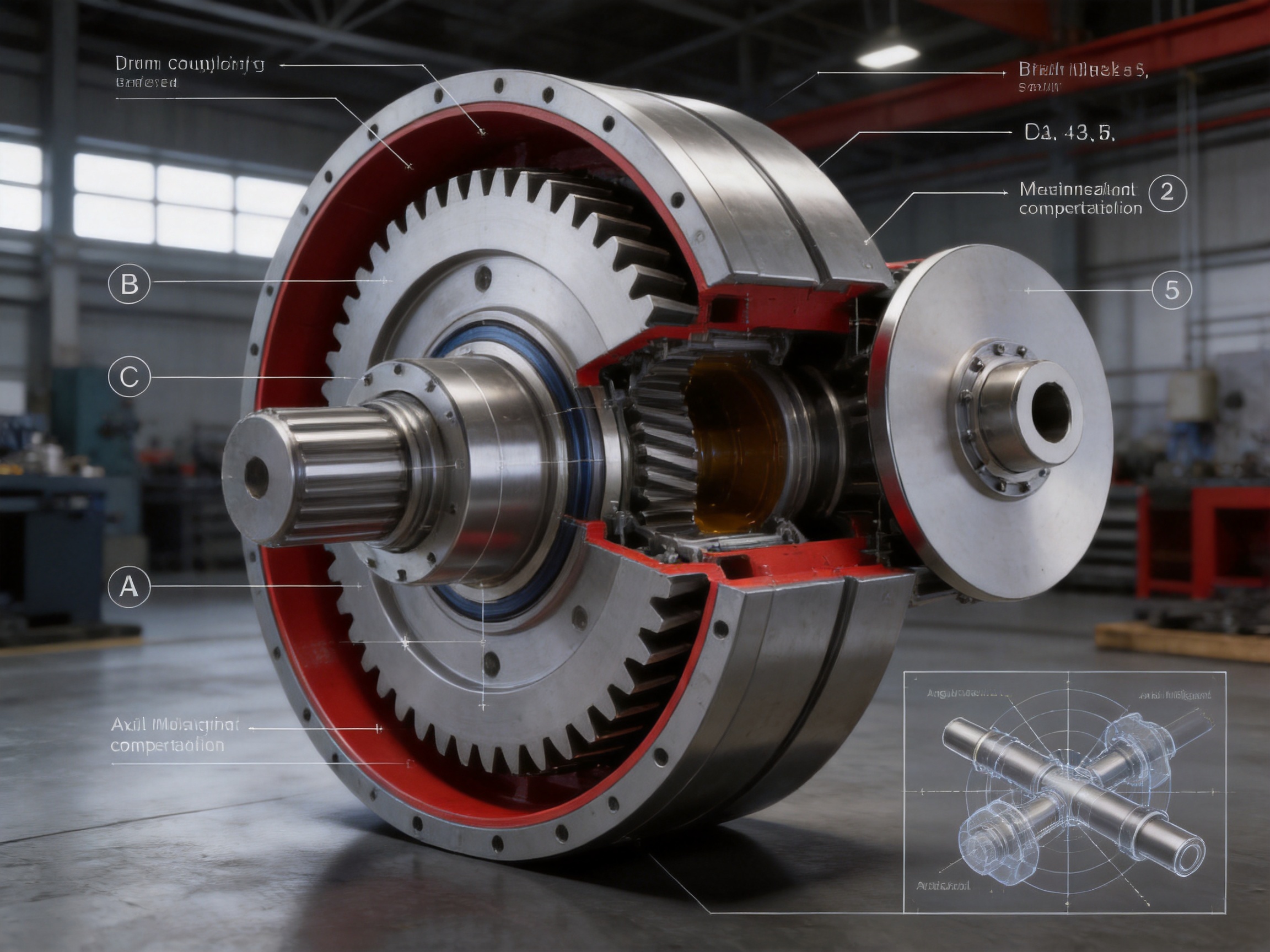
Lifting equipment places special demands on couplings because the drive may start and stop frequently while handling suspended or moving loads. Hoisting mechanisms, crane travel drives, trolley systems, ship loaders, and port conveyors may also operate outdoors in dusty, humid, salty, or fluctuating-temperature conditions.
The brake disc is essential in these systems because controlled stopping and load holding are safety-critical. The coupling must transfer motor torque during lifting while also supporting braking during lowering, positioning, and emergency stopping.
The GAP design is suitable for these duties because it provides high torque capacity, bidirectional rotation, integrated braking support, and misalignment compensation. The design can help maintain stable gear engagement when the load changes rapidly.
For crane applications, selection should include the lifted mass, reeving arrangement, gearbox ratio, motor torque, brake torque, duty classification, number of starts per hour, and expected shock factor. The coupling should not be selected only by comparing motor power with nominal torque.
10. Application in Metallurgical and Mining Equipment
Metallurgical and mining machinery often operates under high loads, impact conditions, dust, vibration, and elevated temperature. Equipment may include rolling mills, conveyors, crushers, feeders, cooling systems, winches, hoists, and material-handling drives.
Gear couplings are well suited to these environments because they can transmit high torque through a robust steel structure. The crowned teeth help accommodate shaft movement caused by thermal expansion and structural deflection.
In mining systems, contamination control is important. Dust and abrasive particles can damage gear teeth and seals if they enter the coupling. Correct sealing, suitable grease, regular inspection, and maintenance procedures are essential. Where the environment is especially severe, customized sealing or protective arrangements may be considered.
In metallurgical machinery, high temperature can affect grease viscosity, seal performance, and shaft alignment. Engineering review should consider the temperature near the coupling, not only the general workshop temperature. Thermal growth calculations may be needed for long shafts or equipment with substantial temperature differences between operating and idle states.
11. Application in Water Treatment, Paper, and Conveyor Systems
Water-treatment equipment may require long operating hours, outdoor installation, and exposure to moisture. The coupling must be protected against corrosion and water ingress while maintaining reliable lubrication.
Paper machines and paper-processing lines often require precise, continuous transmission at controlled speeds. They may also contain long shaft systems with several couplings. Low vibration, accurate balance, and effective misalignment compensation are important for stable operation.
Conveyor systems may use long-distance shafts, large rollers, or multiple drive units. Starting and stopping a loaded conveyor can generate significant torque variation. If a brake is installed, the coupling must be able to withstand the repeated braking cycle without excessive tooth wear or disc runout.
The GAP series can be adapted to these applications through model selection, bore configuration, shaft-hole length, sealing, lubrication, and brake-disc requirements. The most appropriate design depends on the actual machine rather than on the coupling name alone.
12. Lubrication and Maintenance
Gear couplings require suitable lubrication because the teeth experience sliding and rolling contact during misalignment and rotation. Grease reduces friction, limits wear, helps carry away small amounts of heat, and protects the tooth surfaces from corrosion.
The required grease quantity varies by model. The technical data for the GAP series lists approximate grease volumes from several dozen milliliters for smaller models to several liters for larger models. The exact quantity should be confirmed from the product drawing or technical documentation for the selected configuration.
Using too little grease can cause accelerated wear and overheating. Using an unsuitable grease can lead to separation, hardening, leakage, or chemical incompatibility with seals. The grease should be suitable for gear coupling service, operating speed, load, temperature, and environmental conditions.
12.1 Seal Inspection
Seals protect the gear teeth and grease from contamination. A damaged seal can allow water, dust, and abrasive particles to enter the coupling. It can also allow grease to escape, leaving the teeth inadequately lubricated.
The dedicated “e” dimension provides the clearance required for seal replacement. This maintenance-friendly feature may reduce downtime because the seal can be serviced without completely dismantling the system.
During inspection, maintenance personnel should check for grease leakage, hardened or cracked seals, unusual noise, temperature rise, vibration, loose fasteners, and visible tooth damage. If abnormal wear is found, the cause should be investigated rather than simply replacing the coupling.
12.2 Alignment Checks
Alignment should be checked during installation and after major maintenance. Changes in foundation condition, bearing replacement, gearbox work, or machine relocation can alter shaft alignment.
Laser alignment, dial-indicator methods, or other suitable precision techniques may be used. The measured values should be compared with the coupling manufacturer’s permitted limits. The coupling should be installed with the specified axial position and end clearance.
13. Installation Recommendations
Before installation, inspect the coupling for transport damage, corrosion, contamination, and missing parts. Confirm the model, bore combination, shaft-hole length, brake disc diameter, and supplied accessories.
Clean the shaft ends and coupling bores. Remove burrs from keyways and confirm that keys fit correctly without excessive clearance. Do not force components into position with uncontrolled hammering, since impact can damage bearings, seals, gear teeth, or the brake disc.
Check the shaft diameter and shaft extension against the approved drawing. The coupling should be positioned so that the required axial movement and seal-access clearance are available.
Align the shafts accurately before tightening the fasteners. Tighten bolts according to the specified sequence and torque. Confirm that the brake disc rotates freely and that the disc does not contact the brake caliper or lining when the brake is released.
After assembly, apply the specified grease and install seals or covers correctly. Rotate the system by hand where possible to check for interference. For larger systems, carry out a controlled commissioning procedure with gradual speed and load increases.
14. Coupling Selection Method
A systematic selection process reduces the risk of undersizing and premature failure.
14.1 Determine Operating Torque
Calculate or obtain the normal transmitted torque from the motor power and speed:
T = 9550P/n
In this expression, T is torque in N·m, P is power in kW, and n is rotational speed in r/min. The calculated torque should then be multiplied by an appropriate service factor based on load variation, starts and stops, shock, and operating conditions.
14.2 Check Braking Torque
Determine the maximum brake torque and verify that it complies with the coupling requirement:
Tm ≤ 2Tn
The braking torque should be checked together with the service cycle. Frequent braking, emergency stops, suspended loads, and reversing operation may require additional engineering review.
14.3 Check Speed and Inertia
The operating speed must not exceed the allowable speed for the selected model and configuration. The moment of inertia of the coupling and brake disc should be considered in systems with rapid acceleration or deceleration.
A large rotating disc can influence motor starting performance and stopping time. In high-speed equipment, dynamic balance and rotor assembly accuracy become increasingly important.
14.4 Check Bore and Installation Dimensions
Confirm both shaft diameters, shaft-hole lengths, keyways, flange dimensions, brake disc diameter, overall length, and access space. The maximum listed bore diameter for the series reaches 220 mm, but the actual bore depends on the selected model.
14.5 Confirm the Environment
Review temperature, dust, water, corrosive substances, outdoor exposure, vibration, and maintenance access. These factors may influence seal selection, grease choice, surface protection, and customization.
15. Why Manufacturing Capability Matters to Buyers
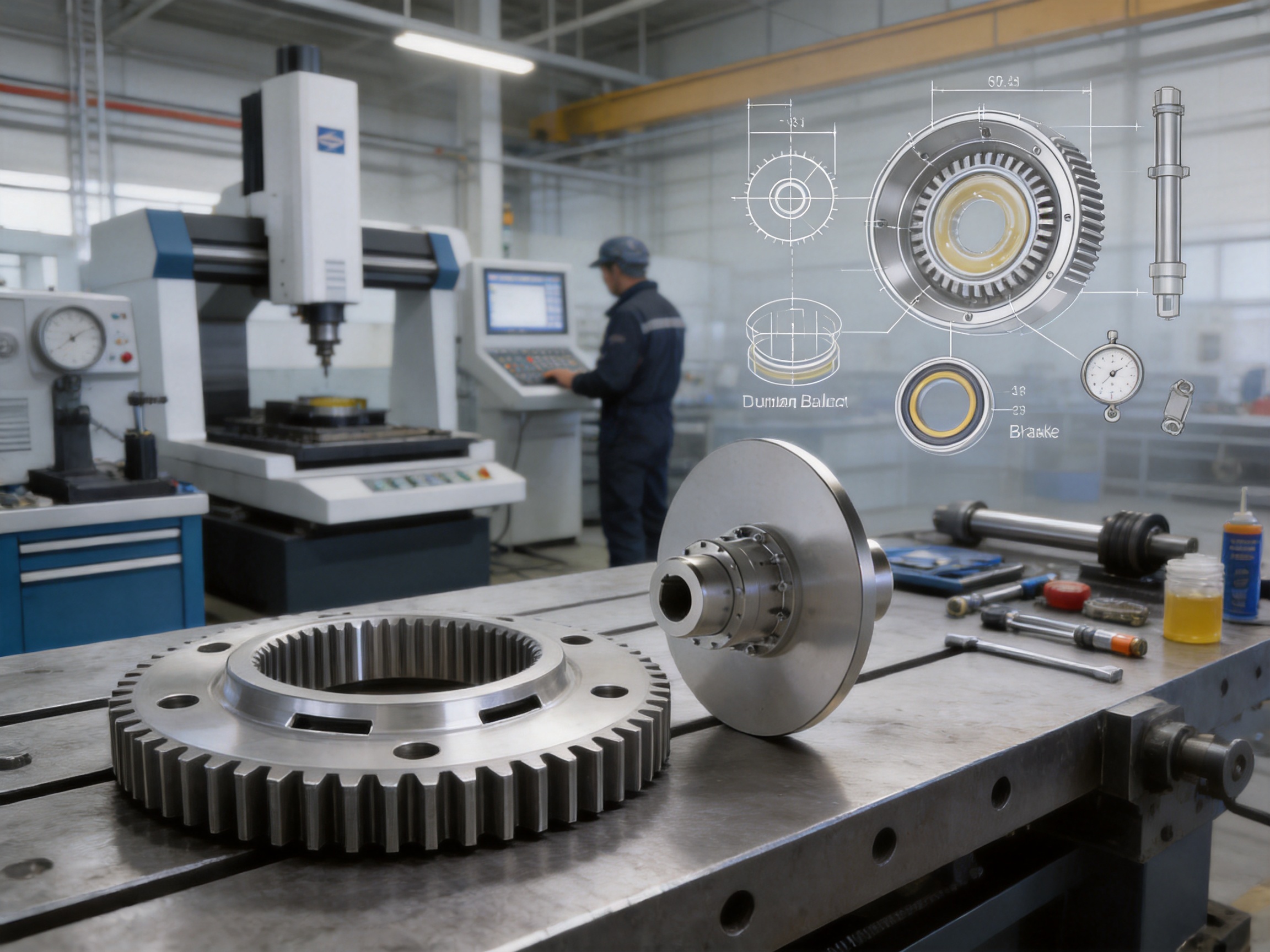
For a high-torque coupling, the supplier’s manufacturing capability is as important as the catalog rating. The component must be produced with consistent geometry, appropriate material treatment, controlled balance, and accurate assembly.
A manufacturer with engineering, machining, testing, and customization capabilities can respond more effectively to unusual shaft dimensions and equipment layouts. It can also investigate application problems through design review rather than treating every issue as a standard replacement transaction.
The manufacturer’s product range includes toothed couplings, elastic sleeve pin couplings, elastic pin couplings, universal couplings, tire couplings, jaw couplings, star couplings, diaphragm couplings, drum couplings, grid couplings, Oldham couplings, flange couplings, clip-shell couplings, roller-chain couplings, safety couplings, and other customized products.
This broad product experience is useful when a customer needs to compare several coupling technologies. Some applications may be better served by an elastic coupling, diaphragm coupling, safety coupling, or universal coupling. A supplier capable of producing multiple types can evaluate the complete transmission requirement rather than promoting a single design regardless of operating conditions.
Quality systems based on ISO 9001 principles support controlled documentation, traceability, inspection records, corrective action, and continuous improvement. These practices are especially valuable for industrial customers purchasing replacement units, large batches, or customized couplings.
16. Limitations and Engineering Considerations
No coupling design is suitable for every application. The GAP drum gear coupling is a strong option for high torque and integrated braking, but it may not be the first choice where exceptional torsional softness, electrical insulation, or zero-maintenance operation is required.
Gear couplings require lubrication and seal maintenance. If a customer needs a completely dry or maintenance-free coupling, another technology may be more appropriate. Gear couplings can also transmit some torsional vibration because their flexible action does not rely on a soft elastomeric element.
The brake disc itself must be matched with the brake caliper, lining material, thermal capacity, and control system. The coupling cannot compensate for an incorrectly sized brake. Disc temperature, cooling, stopping energy, and braking frequency must be evaluated separately.
Allowable misalignment limits must be respected. Excessive misalignment increases tooth sliding and contact pressure, even when the coupling has a strong compensation capability. Proper shaft alignment remains one of the most effective ways to improve coupling life.
17. Recommended Inspection Schedule
The inspection interval should be established according to duty severity. Heavy-duty lifting, mining, metallurgical, and reversing applications may require more frequent inspection than lightly loaded, continuously rotating equipment.
During routine inspection, check the coupling housing, seals, grease leakage, brake disc condition, fasteners, vibration, noise, and temperature. Compare current operating behavior with commissioning data. A gradual increase in noise or temperature may indicate lubrication loss, alignment change, tooth wear, or bearing problems.
During planned shutdowns, inspect the seal condition and replenish or replace grease according to the maintenance manual. If the coupling is opened, examine the tooth surfaces for pitting, scoring, cracks, plastic deformation, or unusual contact marks.
Record inspection results. A maintenance history can reveal changes in operating conditions and help determine whether the coupling is correctly sized for the actual duty.
18. Q&A: Common Questions About the GAP Drum Gear Coupling
Q1: What type of coupling is the GAP product?
The GAP product is a flexible drum gear coupling with an integrated brake disc. It belongs to the category of flexible couplings with non-elastic elements because torque is transmitted through gear teeth rather than through a rubber or metallic elastic element.
Q2: What is the main purpose of the brake disc?
The brake disc provides a rotating friction surface for the braking system. It enables the connected machine to stop, hold, position, or reverse under controlled conditions. The disc is mounted directly to the half coupling so that braking loads are transmitted through the coupling structure.
Q3: Can the coupling rotate in both directions?
Yes. The product supports clockwise and counterclockwise rotation, making it suitable for reversing drives, lifting systems, positioning mechanisms, and equipment with frequent direction changes.
Q4: What is the torque range?
The GAP series covers nominal torque ratings from 630 N·m for GAP1 to 112,000 N·m for GAP14. The correct model must be selected according to operating torque, peak torque, braking torque, speed, bore, and service factor.
Q5: What is the highest listed speed?
The GAP1 model has a listed allowable speed of up to 4,000 r/min. Allowable speed varies by model and configuration, so the selected bore, brake disc, balance condition, and operating environment must be confirmed before use.
Q6: How is axial movement accommodated?
The wider internal gear sleeve provides enhanced axial displacement compensation. This is especially useful in systems with intermediate shafts, thermal expansion, or normal operating movement between connected machines.
Q7: What does the dimension “e” mean?
The dimension “e” provides the clearance needed to replace the seal. This design allows maintenance personnel to service the seal without completely dismantling the transmission system.
Q8: What bore combinations are available?
The listed combinations include Y-Y, J1-J1, Z-Z, Z1-J1, and Y-J1 configurations, subject to model and drawing confirmation. The shaft-hole diameter and length depend on the selected coupling size.
Q9: What is the braking torque limit?
The product specification states that maximum braking torque must not exceed twice the nominal torque, expressed as Tm ≤ 2Tn. The actual brake and coupling selection should also consider inertia, shock, stopping frequency, and emergency braking requirements.
Q10: Does the coupling require lubrication?
Yes. The gear teeth require suitable grease to reduce friction and wear and to protect the contact surfaces. Grease quantity varies by model, and the specified lubricant and maintenance interval should be followed.
Q11: Is customization available?
Yes. Customized bore dimensions, shaft-hole lengths, flange interfaces, brake disc arrangements, sealing solutions, materials, and non-standard structures can be engineered according to the application.
Q12: Which industries commonly use this coupling?
Typical industries include lifting and port machinery, metallurgy, mining, water treatment, paper manufacturing, conveyors, and other heavy industrial transmission systems requiring integrated braking and high torque capacity.
19. Conclusion
The GAP drum gear coupling with brake disc is designed for industrial systems where power transmission and braking must operate together under demanding conditions. Its wider internal gear sleeve improves axial displacement compensation, while crowned gear teeth support stable torque transmission during angular and radial movement.
The direct mounting of the brake disc to the half coupling creates an efficient load distribution path. It allows the coupling to absorb disc weight, braking vibration, and transient torque while helping maintain effective gear-tooth engagement. The product also supports bidirectional rotation, a wide torque range, multiple shaft-hole combinations, large bore sizes, and maintenance access for seal replacement.
Compared with simpler couplings, the GAP series provides a strong combination of high torque density, integrated braking, misalignment compensation, and customization potential. Its performance depends on correct selection, accurate alignment, proper lubrication, suitable braking-system design, and regular inspection.
For buyers, manufacturing capability is a decisive factor. Advanced machining, heat treatment, gear production, balancing, inspection, engineering design, and quality management are necessary to produce a reliable coupling for heavy industrial service. With integrated research, manufacturing, technical support, and customized design capability, the supplier can provide solutions for both standard equipment and non-standard transmission systems.
References
1. Q/YG 12008X-2018, Technical Requirements for GAP-Type Drum Gear Couplings with Brake Discs.
2. Product technical data for GAP1–GAP14 drum gear couplings with brake discs.
3. General engineering principles for gear coupling selection, alignment, lubrication, and maintenance.
4. Industrial transmission design practices for lifting, mining, metallurgy, conveyors, paper machinery, and port equipment.
5. ISO 9001 quality management principles applied to industrial coupling manufacturing.
Product: GAP Drum gear coupling with brake disc (Q/YG 12008X-2018)
- Quick Links
- About
- Products
- Our Service
- News & Events
- Contact
- Products Series
- Flexible Couplings with Non-Elastic Elements
- Flexible Couplings with Metal Elastic Elements
- Flexible Couplings with Non-Metallic Elastic Elements
- Safety Coupling
- Rigid Coupling
- Contact Us
- Tel : +86 511 8572 3800 +86 511 8572 3900
- Mobile : +86 15106109009
- Email : sales@couplingzy.com
- Add:No.1 Zhongye Yingbin Avenue, Gaozi Street, Dantu Economic Development Zone, Zhenjiang City, Jiangsu Province, China.


