:+86 15106109009
:sales@couplingzy.com


 English
 русский
 Español
 عربى
 Português
 Deutsch
 Türk
 Indonesia


GCT Intermediate Sleeve Drum Gear Coupling: High-Capacity Torque Transmission for Heavy Industrial Equipment
Content
- 1 1. Product Positioning and Operating Purpose
- 2 2. Intermediate Sleeve Drum Gear Construction
- 3 3. How the Coupling Transmits Torque
- 4 4. Technical Range of the GCT Series
- 5 5. Advantages Compared with Conventional Coupling Alternatives
- 6 6. Advanced Manufacturing Process
- 7 7. Manufacturing and Service Strengths
- 8 8. Industrial Applications
- 9 9. Selection Method
- 10 10. Installation Recommendations
- 11 11. Maintenance and Service Life
- 12 12. Customization Capabilities
- 13 13. Safety Considerations
- 14 14. Why Choose This Product for Heavy-Duty Drives?
- 15 15. Questions and Answers
- 15.1 Q1: What type of coupling is the GCT intermediate sleeve drum gear coupling?
- 15.2 Q2: What standard is associated with this coupling?
- 15.3 Q3: What is the torque range of the GCT series?
- 15.4 Q4: Does the coupling compensate for all misalignment?
- 15.5 Q5: What is the difference between Type I and Type II?
- 15.6 Q6: Does the coupling require lubrication?
- 15.7 Q7: Can the coupling be customized?
- 15.8 Q8: Is this coupling suitable for high-temperature equipment?
- 15.9 Q9: How should the coupling size be selected?
- 15.10 Q10: What information should be provided for a quotation?
- 15.11 Q11: What industries can use this coupling?
- 15.12 Q12: How can service life be maximized?
- 16 16. Conclusion
- 17 References
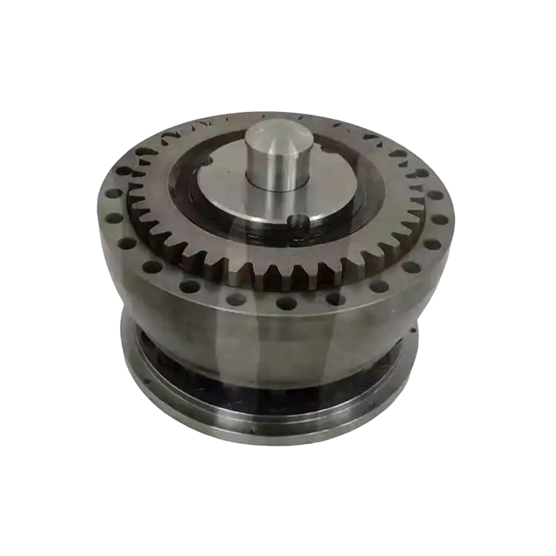
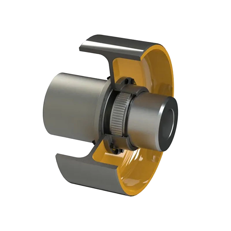
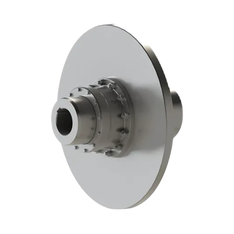
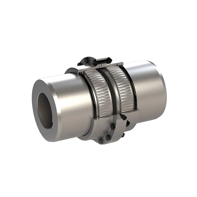
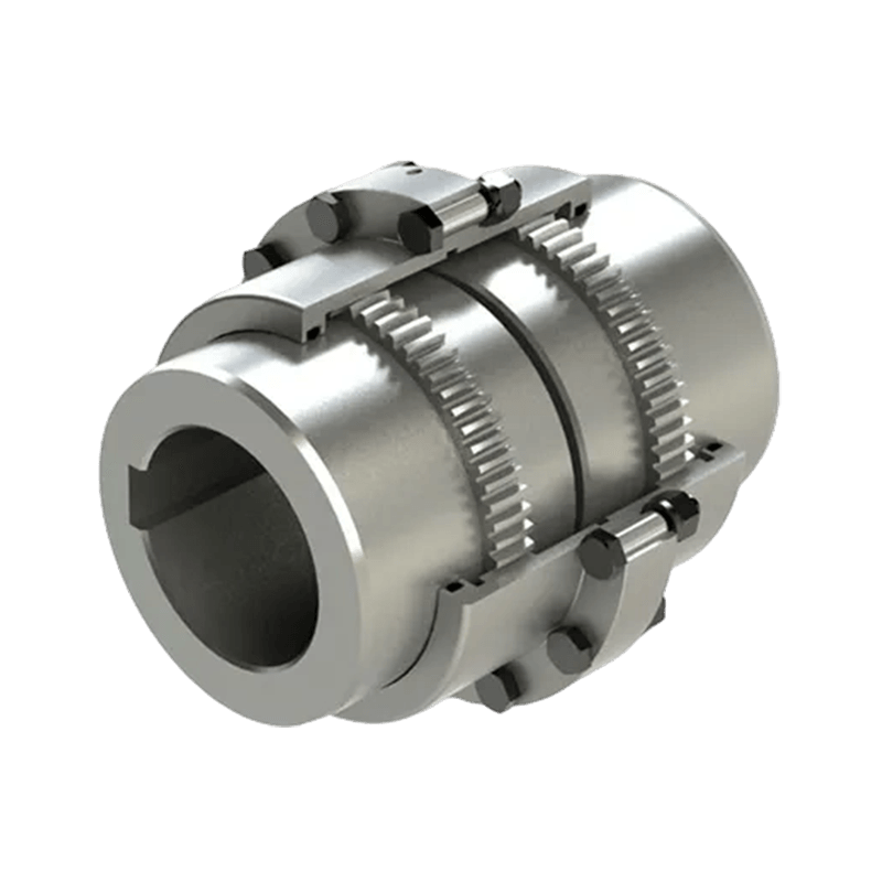
- 18 Product: GCT Connected to intermediate sleeve drum gear coupling(Q/YG 13013X-2018)
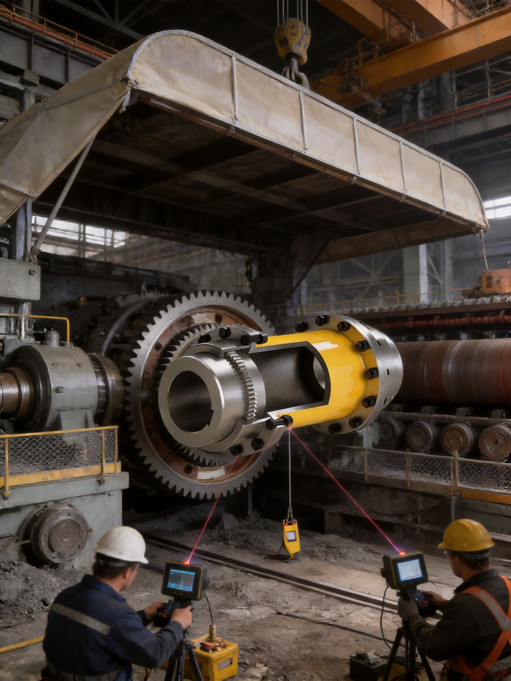
Reliable shaft connection is fundamental to the performance, safety, and service life of heavy industrial machinery. In equipment such as rolling mills, mining machines, lifting systems, conveyors, paper machines, port machinery, water equipment, and large process lines, the coupling must transmit substantial torque while accommodating the misalignment that naturally occurs between connected shafts. It must also withstand vibration, shock loads, temperature variation, dust, moisture, and demanding maintenance conditions.
The GCT intermediate sleeve drum gear coupling is designed for these requirements. Manufactured according to Q/YG 13013X-2018, this high-capacity coupling belongs to the category of flexible couplings with non-elastic elements. Its torque-transmitting components are based on precision-machined gear engagement rather than rubber, polymer, or other elastic inserts. The intermediate sleeve arrangement provides a compact and practical connection between shafts while allowing controlled compensation for axial, radial, and angular alignment deviations.
With nominal torque ratings extending from 800 kN·m to 1,400,000 kN·m across GCT1 to GCT24, the product range covers applications from medium-heavy machinery to extremely large industrial drives. The design combines high torque density, robust construction, flexible installation options, low routine maintenance requirements, and compatibility with a broad range of shaft diameters.
This article examines the construction, operating principle, technical advantages, manufacturing capabilities, application suitability, installation considerations, and selection process for the GCT intermediate sleeve drum gear coupling.
1. Product Positioning and Operating Purpose
A coupling performs more than a simple joining function. It connects the driving shaft of a motor, gearbox, turbine, or other prime mover to the driven shaft of machinery. During operation, it transmits torque and rotational speed while managing the mechanical differences between the two shafts.
In an ideal installation, both shafts would be perfectly aligned. In real equipment, however, several forms of misalignment can develop. Thermal expansion can alter shaft positions, foundation settlement can change centerlines, manufacturing tolerances can affect assembly, and operational loads can cause shafts or housings to deflect. A rigid connection may transfer these deviations directly into the bearings, gearboxes, and connected shafts.
The GCT coupling addresses this issue through its drum gear structure and intermediate sleeve. The external and internal gear profiles maintain torque transmission while allowing limited relative movement between the connected components. This movement helps absorb installation and operating deviations without relying on a flexible rubber element.
Because the coupling does not use a conventional elastic element, it is suitable for high-torque applications where rubber or polymer components could become a limitation. The absence of an elastic insert also avoids problems associated with elastomer aging, hardening, softening, cracking, and temperature-sensitive performance.
1.1 Main Product Characteristics
The GCT series is characterized by the following design features:
1. An intermediate sleeve drum gear arrangement for flexible shaft connection.
2. High nominal torque capacity for heavy-duty mechanical power transmission.
3. Compensation for axial, radial, and angular misalignment within the permitted operating range.
4. A broad range of shaft hole diameters and shaft hole lengths.
5. Two structural configurations, identified as Type I and Type II, for different installation lengths and spatial conditions.
6. Precision gear engagement designed to reduce backlash and support stable torque transfer.
7. Grease lubrication for the gear surfaces and sliding contact areas.
8. Construction suited to harsh industrial environments, including high-load, dusty, corrosive, and temperature-variable conditions when the selected material, sealing, and surface treatment are appropriate.
9. Complete size coverage from GCT1 through GCT24.
10. Availability of engineering support for non-standard dimensions and customized coupling requirements.
2. Intermediate Sleeve Drum Gear Construction
The principal operating components of a GCT coupling are the shaft hubs, gear teeth, intermediate sleeve, end covers or sealing arrangement, fasteners, and lubrication system. Each part has a specific role in maintaining torque transmission and controlled flexibility.
2.1 Shaft Hubs
The shaft hubs are mounted on the driving and driven shafts. They are manufactured with shaft holes selected according to the required shaft diameter, shaft fit, key arrangement, and installation method. The hubs carry the gear teeth or gear-related transmission surfaces that engage with the intermediate sleeve.
The hub design must provide sufficient section thickness around the shaft hole to resist torsional stress, contact pressure, and fatigue loading. In large couplings, the hub also has to manage substantial radial and circumferential forces. Precision machining of the shaft bore, keyway, external diameter, and tooth geometry is therefore essential.
2.2 Drum Gear Teeth
The drum gear profile is the central feature that distinguishes this coupling from a rigid flange connection. Compared with a simple straight-tooth gear coupling, a drum-shaped tooth profile generally provides a more favorable contact condition when angular misalignment is present. The curved tooth form helps maintain useful contact across the tooth width while reducing edge loading.
Effective tooth contact distributes the transmitted torque over multiple teeth rather than concentrating the load at a narrow point. This can reduce local stress, limit wear, and improve operating stability. The exact allowable misalignment, speed, torque, and lubrication requirements must always be confirmed from the approved technical drawing and design calculation for the selected size.
2.3 Intermediate Sleeve
The intermediate sleeve connects the two gear hubs and creates the functional distance between the shafts. Its internal gear surfaces engage with the external gear surfaces of the hubs. The sleeve may be supplied in different structural arrangements depending on the required installation length, shaft spacing, and maintenance access.
Using an intermediate sleeve can be advantageous in applications where the shafts are separated by a defined distance or where the coupling must be installed between large machine components. It also provides a practical route for inspection and lubrication when the coupling is designed with suitable covers and access points.
2.4 Lubrication and Sealing
Gear couplings rely on suitable grease to reduce friction between the tooth flanks and accommodate sliding caused by misalignment. The grease also helps protect the gear surfaces from corrosion and limits wear caused by repeated relative movement.
Sealing is equally important. If grease escapes, or if water, dust, scale, or abrasive particles enter the coupling, tooth wear can accelerate. The sealing system should therefore be selected according to the operating environment. Steel plants, mines, ports, and outdoor lifting equipment may require enhanced protection against dust, water spray, scale, and contaminants.
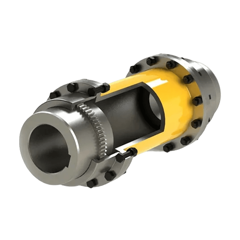
GCT Connected to intermediate sleeve drum gear coupling(Q/YG 13013X-2018)
3. How the Coupling Transmits Torque
When the driving shaft rotates, torque is transferred through its hub and gear teeth to the internal gear surfaces of the intermediate sleeve. The sleeve then transmits the torque through the gear teeth of the second hub to the driven shaft. Since multiple teeth share the load, the coupling can transmit very high torque within a relatively compact radial envelope.
The gear teeth are not intended to operate as a free-running gear set. They are engineered as a shaft connection in which the relative movement is limited and controlled. The coupling must be correctly aligned, properly lubricated, and operated within the specified speed, torque, bore, temperature, and misalignment limits.
3.1 Axial Misalignment
Axial displacement occurs when the distance between the two shaft ends changes. This may result from thermal expansion, bearing movement, machine adjustment, or axial displacement generated by the connected equipment.
The intermediate sleeve and gear engagement permit a designed amount of axial movement. This reduces the possibility that thermal growth or shaft movement will create excessive axial force in the coupling, bearings, or connected machinery. The permitted axial movement depends on the coupling size, tooth design, speed, lubrication, and operating conditions.
3.2 Angular Misalignment
Angular misalignment exists when the centerlines of the two shafts intersect at an angle rather than remaining parallel. The drum-shaped gear teeth are intended to maintain more favorable tooth contact under this condition than a straight rigid connection would provide.
Angular flexibility is particularly valuable in long drive trains, large machines with independent bearing housings, and systems subject to thermal distortion. Nevertheless, flexibility should not be treated as a substitute for proper alignment. The coupling should compensate for reasonable operating movement, not correct severe installation errors.
3.3 Radial Misalignment
Radial or parallel misalignment occurs when the two shaft centerlines remain parallel but are offset from one another. In a drum gear coupling, the tooth geometry allows controlled relative movement that can accommodate a limited radial offset.
Reducing the forces caused by radial misalignment helps protect bearings and shaft extensions. It can also reduce vibration and extend the service life of the coupling. The actual allowable offset should be established from the product drawing and application calculation because excessive radial misalignment can increase tooth pressure and heat generation.
4. Technical Range of the GCT Series
The GCT range includes 24 basic coupling sizes. The series is identified from GCT1 to GCT24, with the nominal torque increasing as the size increases. The smallest listed model, GCT1, has a nominal torque of 800 kN·m, while GCT24 is rated at 1,400,000 kN·m.
The data supplied for the range includes shaft hole diameters, shaft hole lengths, overall diameters, dimensional references for Type I and Type II structures, mass, moment of inertia, and grease quantity. Because the table contains multiple shaft-hole combinations under each basic model, the final selection should be made using the detailed manufacturer drawing rather than by choosing only from the nominal model number.
| Model range | Nominal torque range | Typical shaft-hole coverage | Structural options |
| GCT1 to GCT5 | 800 to 8,000 kN·m | Approximately 16 to 90 mm, depending on model | Type I and Type II |
| GCT6 to GCT10 | 11,200 to 45,000 kN·m | Approximately 32 to 160 mm | Type I and Type II |
| GCT11 to GCT15 | 63,000 to 250,000 kN·m | Approximately 85 to 280 mm | Type I and Type II where specified |
| GCT16 to GCT20 | 315,000 to 800,000 kN·m | Approximately 180 to 400 mm | Mainly heavy-duty large-frame arrangements |
| GCT21 to GCT24 | 900,000 to 1,400,000 kN·m | Approximately 280 to 520 mm | Large industrial configurations |
The ranges in this summary are intended for preliminary engineering reference. Actual shaft-hole combinations, keyway dimensions, hub lengths, maximum speed, dynamic balance requirements, and permissible misalignment must be verified against the selected model drawing.
4.1 Representative Model Data
GCT1 has a nominal torque of 800 kN·m and an outside diameter of approximately 122 mm in the listed configuration. GCT2 increases the nominal torque to 1,400 kN·m, while GCT3 is rated at 2,800 kN·m. GCT4 and GCT5 provide nominal torque ratings of 5,000 kN·m and 8,000 kN·m respectively.
For larger installations, GCT8 is listed at 22,400 kN·m, GCT10 at 45,000 kN·m, GCT12 at 90,000 kN·m, and GCT15 at 250,000 kN·m. The largest listed models reach 1,000,000 kN·m for GCT22, 1,120,000 kN·m for GCT23, and 1,400,000 kN·m for GCT24.
As the torque capacity increases, the coupling dimensions, mass, inertia, shaft-hole sizes, and grease requirements also increase. This progression allows engineers to select a size appropriate for the power train rather than using a single oversized or undersized design.
5. Advantages Compared with Conventional Coupling Alternatives
Coupling selection depends on torque, speed, misalignment, environment, maintenance philosophy, installation space, and cost. No single coupling design is ideal for every machine. However, the GCT intermediate sleeve drum gear coupling provides several advantages over rigid couplings and many elastic couplings in high-torque applications.
5.1 Higher Torque Density Than Many Elastic Designs
Elastic couplings use rubber, polyurethane, composite, or metallic spring elements to provide flexibility and damping. These elements can be highly effective for vibration control, but their torque capacity and temperature resistance may limit their use in exceptionally large drives.
The GCT coupling transmits torque through metallic gear engagement. This provides a robust load path for high-torque service without depending on the strength and fatigue life of a polymeric element. For heavy industrial drives, this can make the gear coupling more suitable than a compact elastic design of similar external dimensions.
5.2 No Elastomer Aging
Rubber and polymer elements can deteriorate due to heat, ozone, oil exposure, ultraviolet radiation, chemical attack, and repeated cyclic loading. Their properties may change over time even when the machine is not operating continuously.
Since the GCT coupling is classified as a flexible coupling without elastic elements, it avoids elastomer aging as a primary failure mechanism. Its service condition remains dependent on gear wear, lubrication, sealing, alignment, material quality, and fatigue loading, but it does not require periodic replacement of a rubber spider, tire, bush, or polymer insert.
5.3 Better Accommodation of Operating Misalignment Than Rigid Couplings
Rigid flange couplings provide a strong and simple shaft connection, but they transfer alignment errors directly into the connected shafts and bearings. They are appropriate only when alignment is tightly controlled and operating movement is negligible.
The drum gear profile of the GCT coupling permits controlled angular, radial, and axial movement. This gives the drive train greater tolerance to normal operating displacement while reducing the mechanical penalties associated with a fully rigid connection.
5.4 High-Load Capability in Harsh Environments
Mining, metallurgy, ports, paper production, and heavy lifting often expose couplings to shock loads, dust, moisture, temperature changes, and frequent load variation. A robust metallic gear coupling can be designed for these conditions through suitable material selection, heat treatment, sealing, lubrication, and surface protection.
The GCT structure is intended for demanding industrial service, and the large model range allows the coupling to be matched to high-capacity equipment. Application-specific environmental protection remains essential, especially where abrasive particles or water can reach the gear teeth.
5.5 Type I and Type II Installation Options
The availability of two structural forms is a practical advantage. Type I and Type II can be selected according to installation length, shaft spacing, available radial clearance, and maintenance access.
This flexibility can help reduce the need for extensive machine redesign. Instead of adapting the entire drive train to one fixed coupling geometry, the engineer can select the structure that best fits the equipment layout.
5.6 Broad Shaft Diameter Compatibility
The GCT series provides numerous shaft-hole combinations. This supports use with different motor shafts, gearbox outputs, mill pinions, rolls, drums, gear reducers, and driven machine shafts.
A broad bore range also helps reduce the need for special adapters. Where the standard bore does not meet the application, customized shaft holes, keyways, shrink-fit arrangements, or other connection details may be considered through engineering review.
6. Advanced Manufacturing Process
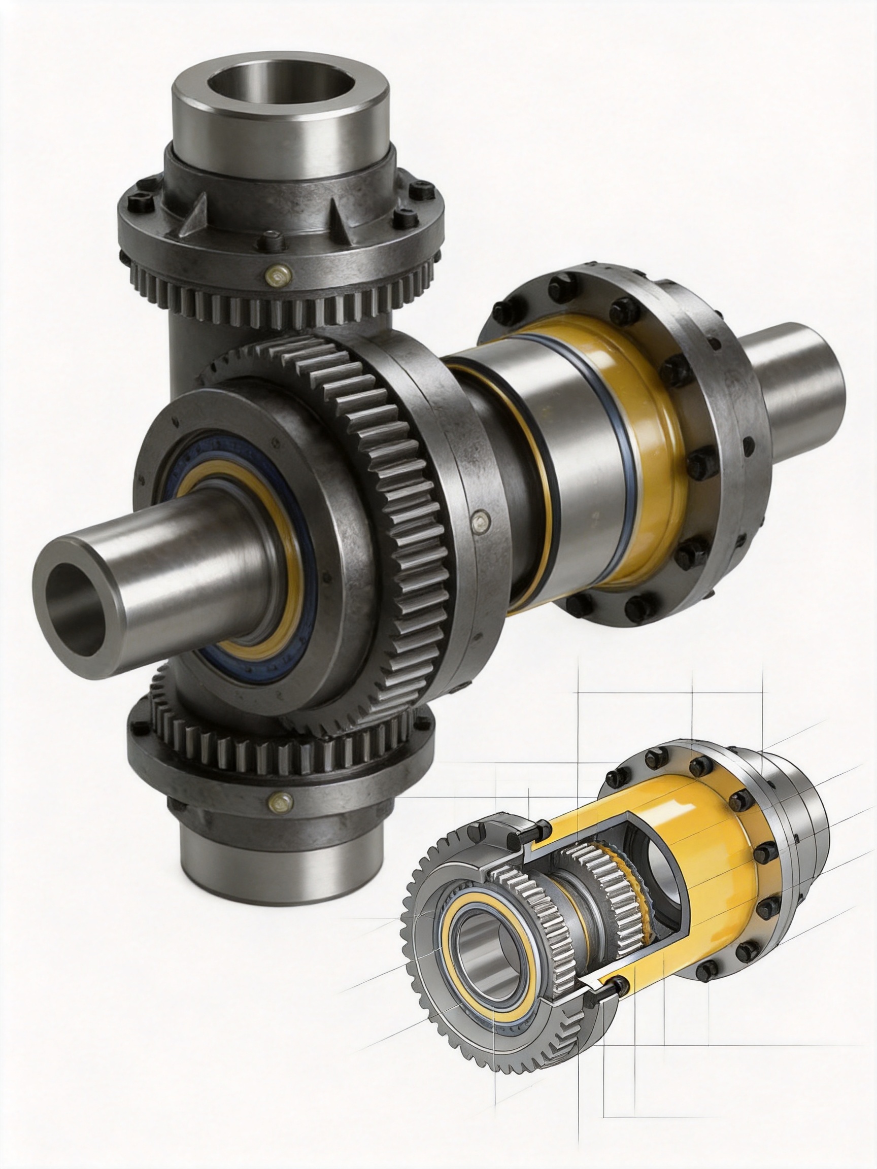
The performance of a large gear coupling depends on the quality of its design and the consistency of its manufacturing process. High nominal torque alone does not guarantee reliability. The gear profile, material condition, heat treatment, dimensional accuracy, balance, surface finish, lubrication channels, sealing arrangement, and inspection process all influence service life.
The manufacturer integrates research and development, manufacturing, testing, sales, technical service, and customization. Its production facilities include a heavy workshop, a precision workshop, offices, warehouse space, and supporting infrastructure. This combination is important for large coupling production because the components may be heavy, dimensionally large, and difficult to handle using ordinary machine-shop resources.
6.1 Engineering and Product Design
Product development begins with torque analysis, shaft interface definition, gear tooth design, dimensional layout, and operating condition review. Engineers must consider nominal torque, peak torque, starting conditions, reversing loads, braking torque, torsional vibration, speed, misalignment, temperature, lubrication, and environmental contamination.
For a customized coupling, the design process may also include shaft stress analysis, key and keyway verification, interference-fit calculations, bearing load review, dynamic balance requirements, and maintenance access evaluation.
Three-dimensional modeling and drawing control help ensure that the intermediate sleeve, hubs, covers, seals, fasteners, and lubrication features are compatible. A controlled design process is especially valuable for large couplings because an error in bore, overall length, or mounting arrangement can significantly delay installation.
6.2 Heavy-Duty Material Processing
High-load coupling components require materials with adequate tensile strength, toughness, hardenability, fatigue resistance, and wear resistance. The material selection depends on the component function. Hubs and sleeves must withstand torsional and bending loads, while gear teeth require a suitable combination of surface hardness and core toughness.
Heavy industrial manufacturing capability allows large forgings, castings, or steel blanks to be processed with appropriate allowances for rough machining, heat treatment, and finish machining. Material certificates and traceability records should be maintained for critical orders.
6.3 Precision Gear Machining
The gear tooth surfaces must be machined accurately so that load is distributed across the intended contact region. Tooth profile, lead, pitch, runout, root geometry, and surface finish all affect operation.
Precision machining is particularly important in a drum gear coupling because the profile must support relative movement without creating harmful edge contact. Controlled gear cutting, inspection, and finishing help ensure that the sleeve and hub teeth work as a matched assembly.
For large components, the manufacturer must also manage deformation and dimensional change caused by material removal, handling, and heat treatment. Process planning may include rough machining before heat treatment followed by semi-finish and finish machining after the material condition has stabilized.
6.4 Heat Treatment and Surface Performance
Gear teeth experience repeated contact stress and sliding. Appropriate heat treatment can improve wear resistance, contact fatigue strength, and dimensional stability. The precise treatment depends on the selected steel grade, tooth size, required hardness profile, and service conditions.
Good practice includes controlled furnace parameters, hardness testing, inspection of treated surfaces, and verification that the tooth surface remains free from unacceptable cracks, burns, distortion, or decarburization.
6.5 Dimensional Inspection
Inspection should cover shaft holes, keyways, hub lengths, tooth geometry, outside diameters, sleeve dimensions, end-face runout, concentricity, axial location, and assembly fit. Large coupling components may require coordinate measurement, gear inspection equipment, dial indicators, micrometers, bore gauges, and other calibrated instruments.
Inspection records provide evidence that the delivered coupling conforms to the approved drawing. They also establish a useful reference for future replacement components and maintenance evaluation.
6.6 Assembly and Functional Verification
Before shipment, the coupling components should be checked as an assembly. The inspection may include verification of tooth engagement, axial movement, cover fit, sealing condition, lubrication ports, fastener installation, and identification markings.
Where required by the application, balance testing, runout checks, trial fitting, or special load and dimensional verification can be included. The inspection scope should reflect the coupling speed, torque level, safety classification, and customer requirements.
7. Manufacturing and Service Strengths
The company behind the product combines design, production, sales, and technical support. This integrated model provides several practical benefits to customers purchasing heavy-duty couplings.
7.1 Research and Development Capability
A dedicated technical team can develop standard and non-standard coupling solutions. This is valuable when the customer has unusual shaft spacing, restricted installation access, special bore requirements, a unique key arrangement, or an existing coupling envelope that must be maintained.
Engineering support can also assist with torque selection, service factor evaluation, material selection, lubrication recommendations, installation procedures, and replacement coupling verification.
7.2 Heavy and Precision Workshops
The production site includes a heavy workshop for large components and a precision workshop for close-tolerance machining. These two capabilities complement each other. Heavy equipment is required to handle large coupling bodies, while precision equipment is required to finish bores, gear teeth, reference faces, and sealing surfaces.
The combination reduces dependence on fragmented external processing and helps maintain control over production quality, scheduling, and technical changes.
7.3 Testing and Quality Control
Quality control is supported by testing facilities and documented manufacturing procedures. Depending on the order, quality assurance may include incoming material inspection, process inspection, heat-treatment verification, dimensional inspection, gear-tooth inspection, non-destructive testing, assembly checks, and final documentation.
ISO 9001-related quality management practices support the control of design documents, purchasing, production, inspection, nonconformance, corrective action, and customer feedback. Certification should be confirmed against the current scope and validity for the specific supplier and order.
7.4 Complete Coupling Product Portfolio
In addition to gear couplings, the company manufactures or supplies elastic sleeve pin couplings, elastic pin couplings, gear couplings with elastic pins, universal couplings, tire couplings, jaw couplings, star couplings, diaphragm couplings, drum couplings, grid couplings, Oldham couplings, flange couplings, clamp-shell couplings, roller-chain couplings, safety couplings, and other designs.
This broad product knowledge can help customers compare alternatives rather than selecting a coupling in isolation. For example, an elastic coupling may be preferable where vibration damping is the priority, while a diaphragm coupling may be appropriate for high-speed precision equipment. A gear coupling becomes attractive where high torque, compactness, and misalignment capability are more important than torsional damping.
8. Industrial Applications
8.1 Metallurgical Equipment
Rolling mills, furnace equipment, material handling lines, and other metallurgical machines impose high torque and shock loads on drive trains. Couplings may also be exposed to heat, scale, vibration, and difficult access.
The GCT series can be considered for large rolling and transmission systems where a non-elastic high-capacity coupling is required. Environmental protection, thermal effects, lubrication, and maintenance access must be reviewed carefully.
8.2 Mining Equipment
Mining machinery often operates continuously under severe loading. Crushers, conveyors, hoists, mills, and processing machines may experience impact loads, dust, water, and irregular material flow.
A properly selected GCT coupling can transmit high torque while allowing controlled misalignment between drive components. Seals and lubrication must be selected to prevent abrasive contamination from reaching the gear teeth.
8.3 Lifting and Hoisting Machinery
Lifting equipment has demanding safety requirements because acceleration, deceleration, braking, and reversing can create transient torque. The coupling must be evaluated for peak torque, emergency braking, duty cycle, and fatigue.
The coupling selection should be integrated with the brake, gearbox, drum, motor, and control system. A suitable service factor is essential, and all applicable safety standards must be observed.
8.4 Port and Marine-Adjacent Equipment
Port machinery, ship loaders, reclaimers, cranes, conveyors, and transfer systems may be exposed to humidity, salt-laden air, dust, and outdoor temperature changes. The GCT coupling can be adapted with suitable corrosion protection, sealing, grease, and surface treatment.
Where equipment is exposed directly to marine conditions, the customer should specify the environmental classification so that material and coating decisions are made during design rather than after installation.
8.5 Paper and Pulp Equipment
Paper machines and pulp-processing equipment often contain long shaft lines and operate continuously at controlled speed. Alignment changes may arise from thermal effects, foundation movement, and maintenance activities.
The gear coupling's misalignment capability can be useful in these systems, provided that rotational speed, balance, lubrication, and sealing are compatible with the application.
8.6 Water and Process Equipment
Large pumps, mixers, clarifiers, water-treatment drives, and process machinery require dependable torque transmission and low interruption risk. In outdoor or wet installations, protection against water ingress and corrosion is critical.
9. Selection Method
Selecting the correct GCT coupling requires more than matching the motor power to a nominal model. The following steps provide a practical preliminary method.
9.1 Determine Operating Torque
Calculate the continuous operating torque using the machine power and shaft speed. When power is expressed in kilowatts and speed in revolutions per minute, the approximate torque in newton-meters can be calculated as:
Torque = 9550 × Power in kilowatts ÷ Speed in revolutions per minute.
The resulting operating torque should then be adjusted for starting conditions, impact loads, reversing duty, braking, cyclic operation, and other service factors.
9.2 Check Peak and Transient Loads
Crushers, rolling equipment, hoists, conveyors with irregular loading, and reversing drives may produce peak torque far above the average operating value. The coupling must be checked for both continuous and peak torque.
Where the machine has high torsional vibration or frequent starts and stops, a torsional analysis may be necessary. The coupling's moment of inertia can influence the dynamic behavior of the drive train, particularly in high-speed or highly flexible systems.
9.3 Confirm Shaft Diameters and Connection Details
Record both shaft diameters, shaft lengths, keyway dimensions, allowable hub length, shaft-end configuration, and required fit. The GCT data includes multiple shaft-hole options, but not every combination is available for every model.
Also verify whether the shafts require a standard keyed bore, an interference fit, a splined connection, a special key, or a customized interface.
9.4 Evaluate Installation Space
Measure the distance between shaft ends, radial clearance, axial access, cover removal space, and the available lifting equipment. Select Type I or Type II according to the machine layout.
Large couplings can be heavy. The installation plan should include lifting points, temporary supports, access platforms, and a safe method for positioning the intermediate sleeve.
9.5 Review Speed and Balance
The nominal torque rating does not by itself determine the maximum operating speed. Rotational speed, coupling diameter, balance grade, shaft arrangement, and dynamic behavior must be reviewed together.
High-speed applications may require dynamic balancing, tighter runout limits, special inspection, or a different coupling type. The manufacturer should confirm the permissible speed for the selected size and structure.
9.6 Consider the Environment
Specify ambient temperature, moisture, dust, abrasive particles, corrosive chemicals, scale, washdown conditions, and outdoor exposure. These factors affect grease selection, sealing, coatings, materials, and maintenance intervals.
9.7 Verify Misalignment Requirements
Measure the expected installation and operating misalignment. The coupling should be selected so that normal movement remains comfortably within the permitted limits. Designing at the absolute maximum misalignment may increase tooth pressure and reduce service life.
10. Installation Recommendations
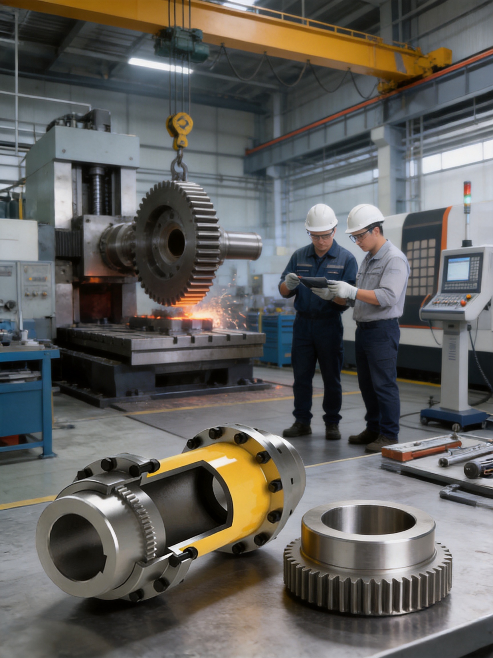
Correct installation is essential for achieving the rated performance of a gear coupling. Even a high-quality coupling can suffer premature wear if the shafts are poorly aligned, the teeth are contaminated, or the lubricant is unsuitable.
10.1 Preparation
Inspect the shafts, keyways, hubs, sleeve, gear teeth, seals, fasteners, and mounting surfaces before assembly. Remove burrs, rust, dirt, scale, and protective material that could interfere with the fit.
Confirm that the coupling model, bore dimensions, keyway details, and structural type match the approved drawing. Check that the shaft extensions provide sufficient engagement without creating interference between the hubs and sleeve.
10.2 Alignment
Align the connected shafts using suitable instruments. Depending on the machine and accuracy requirement, alignment may involve dial indicators, laser alignment equipment, straightedges, feeler gauges, or a combination of methods.
Initial alignment should be better than the maximum coupling allowance whenever possible. The final alignment should consider thermal growth, operating load, and the manufacturer's recommended offsets.
10.3 Hub Installation
Install the hubs using the specified fit and method. Do not force a hub onto the shaft by striking the gear teeth, sleeve, or sealing components. If heating is required for an interference fit, control the temperature carefully and protect seals and finished surfaces.
Verify the axial position of each hub. Incorrect hub positioning can reduce tooth engagement, limit axial movement, or create contact between components that should remain clear.
10.4 Sleeve and Cover Installation
Install the intermediate sleeve without damaging the gear surfaces or seals. Apply the recommended grease to the tooth flanks and sliding surfaces before closing the coupling. Use only a compatible lubricant with suitable load-carrying ability and temperature range.
Tighten fasteners according to the specified sequence and torque. Confirm that covers are seated correctly and that lubrication ports or inspection openings are accessible.
10.5 Pre-Start Inspection
Before starting the machine, rotate the shaft by hand where possible. Check for abnormal resistance, interference, uneven movement, or contact. Verify that all guards are installed and that no tools or foreign objects remain near the coupling.
During the first operating period, monitor vibration, temperature, noise, grease leakage, and fastener condition. Stop the equipment if there is abnormal knocking, rapid heating, metal dust, or significant lubricant loss.
11. Maintenance and Service Life
Gear couplings are relatively low-maintenance compared with many flexible couplings, but they are not maintenance-free. Planned inspection and lubrication are necessary to preserve gear contact and sealing performance.
11.1 Lubrication Management
Use the grease grade recommended for the coupling and environment. Do not mix incompatible greases without confirming compatibility. Maintain the correct quantity: insufficient grease can cause wear and heat, while excessive grease may increase churning or pressure on seals.
Lubrication intervals depend on speed, temperature, load, contamination, operating hours, and sealing performance. Heavy-duty continuous applications may require more frequent inspection than lightly loaded intermittent drives.
11.2 Inspection of Gear Teeth
During scheduled maintenance, inspect the tooth surfaces for pitting, scoring, abnormal polishing, fretting, corrosion, and uneven contact. Tooth wear concentrated at one edge may indicate excessive angular or radial misalignment.
Metal particles in the grease can indicate abnormal wear. If such particles are found, the equipment should be investigated before the coupling is returned to service.
11.3 Seal Inspection
Inspect seals for cracking, hardening, deformation, leakage, and loss of flexibility. A damaged seal should be replaced promptly because contamination can quickly reduce gear life.
11.4 Alignment Checks
Recheck alignment after bearing replacement, gearbox maintenance, foundation work, thermal events, or significant vibration changes. Machine movement can alter the coupling operating position even when the coupling itself has not been disturbed.
11.5 Record Keeping
Maintain records of operating hours, lubrication, alignment measurements, vibration readings, inspections, and component replacement. These records help establish a condition-based maintenance program and identify developing problems before an unexpected shutdown.
12. Customization Capabilities
Standardized products provide efficiency, but many heavy industrial machines require customized coupling details. The manufacturer undertakes non-standard coupling design and production, subject to engineering review.
Potential customization areas include shaft-hole diameter, keyway size, shaft-hole length, hub extension, overall coupling length, intermediate sleeve dimensions, mounting arrangement, cover design, sealing, corrosion protection, material grade, heat treatment, lubrication ports, balance requirements, and special inspection documentation.
Customized design should begin with a complete technical data sheet. This should include transmitted power, operating speed, peak torque, shaft diameters, shaft lengths, shaft spacing, alignment conditions, environmental temperature, contamination, duty cycle, braking loads, installation limitations, and required standards.
Customization is most successful when the coupling manufacturer is involved before the machine layout is finalized. Early engineering coordination can prevent interference, reduce unnecessary size, and make future maintenance easier.
13. Safety Considerations
A rotating coupling is a potentially hazardous machine component. It must be enclosed by a suitable guard that prevents contact with rotating parts and protects personnel from lubricant, fragments, or failed components.
Installation and maintenance should be performed only after the machine has been isolated, locked out, and secured against unexpected rotation. Heavy components require properly rated lifting equipment and trained personnel.
Do not operate the coupling above its approved speed, torque, temperature, or misalignment limits. Do not remove guards while the equipment is running. Do not weld, drill, or modify the coupling without written engineering approval.
When a coupling is used in a lifting, hoisting, braking, or other safety-critical system, the complete machine must be assessed according to applicable regulations and customer safety procedures. Coupling selection is one part of the safety design and does not replace system-level risk assessment.
14. Why Choose This Product for Heavy-Duty Drives?
The GCT intermediate sleeve drum gear coupling offers a balanced combination of high torque capacity, controlled flexibility, broad size coverage, and practical installation options. Its metallic gear transmission avoids the aging limitations of elastomeric elements, while the drum gear profile allows more movement than a rigid flange connection.
The product is especially compelling when the drive requires:
High torque transmission in a compact and robust coupling arrangement.
Compensation for normal axial, radial, and angular shaft movement.
Resistance to heavy mechanical loading and industrial operating conditions.
A wide choice of shaft-hole diameters and coupling sizes.
Type I or Type II structural options for different installation layouts.
Low routine maintenance compared with couplings that require frequent elastic element replacement.
Engineering assistance for non-standard shaft interfaces or special environmental conditions.
Manufacturing support from a supplier with heavy machining, precision production, testing, quality control, and multiple coupling technologies.
Compared with less specialized suppliers, an integrated manufacturer can provide greater continuity between design, production, inspection, delivery, installation support, and after-sales service. This is particularly important for large couplings, where a dimensional error or delayed replacement can affect an entire production line.
15. Questions and Answers
Q1: What type of coupling is the GCT intermediate sleeve drum gear coupling?
The GCT is a flexible coupling with non-elastic elements. It uses metallic gear engagement and an intermediate sleeve to transmit torque while allowing controlled axial, radial, and angular misalignment. It does not depend on a rubber or polymer elastic insert.
Q2: What standard is associated with this coupling?
The product is identified with the standard number Q/YG 13013X-2018. The final technical drawing, inspection requirements, and customer specification should be used to confirm the applicable product details for each order.
Q3: What is the torque range of the GCT series?
The listed GCT range extends from 800 kN·m for GCT1 to 1,400,000 kN·m for GCT24. The correct model must be selected after considering operating torque, peak loads, speed, service factor, and environmental conditions.
Q4: Does the coupling compensate for all misalignment?
No. It compensates for a designed amount of axial, radial, and angular misalignment. It should not be used to correct severe installation errors. Shaft alignment should be performed accurately, and the permitted values for the selected model must be respected.
Q5: What is the difference between Type I and Type II?
Type I and Type II are two structural forms intended for different installation lengths and space requirements. The suitable form depends on shaft spacing, available clearance, hub arrangement, and maintenance access.
Q6: Does the coupling require lubrication?
Yes. The gear teeth and sliding contact areas require suitable grease. Lubricant type, quantity, sealing, and replenishment interval should follow the manufacturer's technical documentation and the actual operating conditions.
Q7: Can the coupling be customized?
Yes. Customization may include shaft holes, keyways, shaft-hole lengths, overall dimensions, covers, seals, materials, coatings, lubrication arrangements, balance requirements, and other non-standard details, subject to engineering confirmation.
Q8: Is this coupling suitable for high-temperature equipment?
It can be considered for high-temperature applications when the material, grease, seals, clearances, and thermal expansion conditions are properly designed. The actual operating temperature limit must be confirmed for the selected configuration.
Q9: How should the coupling size be selected?
Start with the operating and peak torque, then check speed, service factor, shaft diameters, shaft spacing, misalignment, environment, bore fit, and installation constraints. The nominal torque rating alone is not sufficient for final selection.
Q10: What information should be provided for a quotation?
Provide the required power, speed, operating torque, peak or starting torque, shaft diameters, shaft lengths, shaft spacing, keyway details, installation orientation, ambient conditions, expected misalignment, duty cycle, and any applicable standards or inspection requirements.
Q11: What industries can use this coupling?
Typical industries include metallurgy, mining, lifting, ports, paper production, water equipment, process machinery, conveyors, and other heavy industrial applications requiring reliable high-torque shaft connection.
Q12: How can service life be maximized?
Use correct alignment, proper grease, effective sealing, suitable operating limits, regular inspection, secure fasteners, and timely replacement of damaged seals. Monitoring vibration, temperature, noise, and grease condition can help detect problems early.
16. Conclusion
The GCT intermediate sleeve drum gear coupling is a heavy-duty solution for industrial power transmission where torque capacity, flexibility, durability, and service reliability are essential. Its drum gear design allows controlled compensation for shaft misalignment, while its non-elastic metallic transmission path avoids many limitations associated with rubber and polymer elements.
The GCT1 to GCT24 range provides broad coverage for medium-heavy through extremely large applications. Multiple shaft-hole combinations, Type I and Type II structures, high nominal torque ratings, and customization capability allow the coupling to be adapted to diverse machine layouts.
Its performance depends on more than the product design. Correct sizing, accurate shaft alignment, appropriate lubrication, effective sealing, proper installation, and planned maintenance are all necessary. By combining these practices with controlled materials, precision gear machining, heat treatment, dimensional inspection, assembly verification, and technical support, the manufacturer can provide a dependable coupling solution for demanding industrial equipment.
For customers seeking a high-capacity flexible coupling without an elastic element, the GCT intermediate sleeve drum gear coupling offers a strong combination of mechanical performance, manufacturing depth, application versatility, and long-term service value.
References
1. Q/YG 13013X-2018, Technical Standard for GCT Intermediate Sleeve Drum Gear Couplings.
2. Manufacturer Technical Data, Basic Parameters and Main Dimensions of GCT Intermediate Sleeve Drum Gear Couplings.
3. General Principles of Industrial Shaft Alignment and Coupling Installation.
4. Industrial Gear Coupling Design, Lubrication, and Maintenance Practices.
5. ISO 9001, Quality Management Systems: Requirements.
6. Industrial Machinery Safety Principles for Rotating Equipment and Coupling Guards.
Product: GCT Connected to intermediate sleeve drum gear coupling(Q/YG 13013X-2018)

- Quick Links
- About
- Products
- Our Service
- News & Events
- Contact
- Products Series
- Flexible Couplings with Non-Elastic Elements
- Flexible Couplings with Metal Elastic Elements
- Flexible Couplings with Non-Metallic Elastic Elements
- Safety Coupling
- Rigid Coupling
- Contact Us
- Tel : +86 511 8572 3800 +86 511 8572 3900
- Mobile : +86 15106109009
- Email : sales@couplingzy.com
- Add:No.1 Zhongye Yingbin Avenue, Gaozi Street, Dantu Economic Development Zone, Zhenjiang City, Jiangsu Province, China.


